If all you have is a HeNe tube but no power supply, see the section: Testing a HeNe Laser Tube Without a Compatible Power Supply for ways to determine if the tube is good. The following applies to both bare HeNe tubes and laser heads though some of the inspection and/or tests will require removing the tube from any enclosure.
Several types of problems can prevent a HeNe tube from lasing properly or make it hard to start:
However, such damage could be an indication of a trauma that misaligned the mirrors - though this is quite unlikely - see the next paragraph.
Thus, if your HeNe tube appears to be glowing like a neon sign or fluorescent lamp (outside the bore) and starts at a very low voltage - perhaps half of the normal *operating* voltage specified for the tube - this may be the cause. A way of detecting it without powering the tube if the problem isn't obvious by inspection (it is hidden inside a laser head) or from the way the tube rattles, sight down the bore of the unpowered tube. In all likelihood, the capillary will now be misaligned enough such that one or both ends will be way off-center or not even visible. And, if it is still held in place by any metal spacer(s) that may be present, there will be no clear path through from one end to the other. Unfortunately, there is no way of repairing such damage. Where only a small part of the bore has broken off, the tube may still lase weakly if the broken part isn't blocking the internal beam path (or it can be jiggled such that this is the case). However, power will be way down.
Note: if you have a high power (long) tube, mirror alignment may not be correct until the tube warms up and/or external permanent adjusters may be required to stabilize the mirrors. Without these, there may be no, low, or fluctuating power. Very slightly pressing on the mirror mounts - or even on various parts of the tube itself - (with a well insulated tool!) will result in a significant variation in power. There may also be a "This Side Up" label on the tube or head indicating the proper orientation for optimal performance. Parts in the tube droop due to gravity (not the electrons, ions, or photons!). This probably applies mostly to HeNe tubes that are greater than 15 to 20 mW, are "other-color" (e.g., green) tubes, and possibly only some types and condition. However, there could be some less dramatic effects with shorter tubes. In addition, just touching one side of the tube with your hand will cool it which may result in a noticeable power change due to the slight contraction which results in a minute but significant bending of the tube and chance in mirror parallelism!
See the section: Checking and Correcting Mirror Alignment of Internal Mirror Laser Tubes for more information.
Aside from manufacturing defects, one way for such a failure to occur is for a power supply fault to drive grossly increased current through the HeNe tube. It is possible for this to result in an abrupt termination of the discharge inside the bore and an inductive kick and huge voltage spike due to the wiring. With the bore momentarily unavailable, the only other path is for an arc through the glass barrier. Like the failure of a MOSFET gate oxide due to electrostatic discharge, once any breech develops, it does not heal! The addition of a spark gap surge protector sized to break down at just over the specified starting voltage may represent a prudent precaution when driving large expensive higher power HeNe tubes. Figure about 25 kV per inch - though this can vary considerably depending on the shape of the electrodes and environmental conditions.
This is one reason not to use a power supply much larger than needed for your particular HeNe tube. I found out the hard way when while violating my recommendation not to use a microwave oven transformer, this happened with a large (35 mW) HeNe tube due to a wrong connection which bypassed the ballast resistor. It was not pretty :-(. The HeNe tube is now good as a sort of high tech neon sculpture but not much else. I even found a defective power supply brick - inadequate start voltage - that powers the sculpture just fine. Now to put it all on a nice polished wood base. :)
See Color of HeNe Laser Tube Discharge and Gas Fill for some not too terrible renderings of a normal tube's bore and some typical problems. (Of course, your computer monitor has to be reasonably well adjusted for these to be at all accurate.) Discharge viewing must be through a glass part of the tube, not the mirrors since their transmission wavelengths will dominate. For an enclosed laser head, it may be necessary to remove one of the plugs on the side or the anode end end-cap (taking care around the high voltage!). The comments about output apply to red HeNe tubes; orange, yellow, green, and near-IR HeNe tubes will likely produce no output at all unless the gas fill is nearly perfect. However, to maximize gain, "other color" HeNe laser tubes will likely have a slightly different discharge color due to modifications to the ratio of He:Ne, the isotopic purity of the gases, and other unknown factors. So, before you blame bad gas, make sure your tube is indeed the normal red variety. As examples of other color tubes:
Various shades of red, blue, and white are symptoms of gas fill problems. Since the total amount of helium and neon in a typical 1 mW HeNe tube is much less than a cubic cm - if returned to atmospheric pressure, almost any leakage or contamination is significant and will likely prevent lasing. Where the tube is 'up to air', no discharge will take place. And, a state of affairs anywhere in between is possible and especially common for old soft-seal tubes. Loss of helium through diffusion is can take place as well. Each of these cases is discussed below.
However, without a spectrophotometer or optical spectrum analyzer, you won't be able to see slight changes in discharge color and these may be enough to kill lasing (though normally, they will be obvious). The only way to really determine if the color is correct where it looks correct and you happen not to have fancy instrumentation is to do a side-by-side comparison with an identical working HeNe tube. I say 'identical' because there can be subtle variations in the normal gas fill from different manufacturers (and from different color HeNe tubes). It may also be possible to take photos (digital or otherwise) of the two tubes (if you don't have two power supplies to run them simultaneously) and then compare those, but getting good color rendition may be a challenge.
Note also that the brightness of the discharge at the same current will almost always be lower with gas fill problems. This may not be immediately obvious unless a good and bad tube are run side-by-side but then it can be quite striking.
If the tube has a getter electrode (see the section: HeNe Laser Tubes and Laser Heads), check the color of the getter spot on the glass in its vicinity. The function of the getter spot is to combine with any unwanted non-noble gases (mostly oxygen and nitrogen) and should generally be black or metallic in appearance if still functional. A milky white, red, or brown color generally indicates that significant air leakage has occurred and the tube is probably no longer functional. Sure, it might be on the hairy edge but this isn't likely! (Note that sometimes a tube will be manufactured with a getter electrode but for whatever reason, it was never activated, the active material remained within its structure, or the active material is transparent. Thus, there is no getter spot, good or bad, and therefore no way to know - from this at least - whether there has been leakage. (For example, all normal (non-barcode scanner) Melles Griot HeNe laser tubes have a getter electrode but no getter spot regardless of gas-fill condition. So there's really no way to know their state of health for the getter.) It may be possible to reactivate the getter electrode by heating it by RF induction or some other means to drive off more getter material that may be present but (1) this is definitely for the advanced course and (2) the likelihood of helping the HeNe tube at this point is small unless the amount of leakage was very very infinitesimal.
(From: Don Klipstein (Don@misty.com).)
I have rejuvenated a couple soft-seal HeNe tubes by heating the getters, either with a glow discharge or a Solar furnace made with an overhead projector Fresnel lens.
(From: Sam.)
I have also revived both a red and a green Melles Griot HeNe laser tube using a jerry-rigged Solar furnace made from a $1, 7" x 10" plastic Fresnel lens intended as a reading magnifier. See the sections: HeNe Tube Lases but Color of Discharge Changes Along Length of Bore and Melles Griot GreNe with No Output for details.
Any source of RF power can be used to determine if a bare tube still has a reasonably low internal pressure (but not if it will lase). However, RF excitation cannot be used to test enclosed laser heads because it is generally not possible to view the inside of the actual HeNe tube and the (metal) case would prevent RF penetration or create other problems.
I haven't tried it, but this approach may even be an effective way for starting some HeNe tubes (even one that is normally hard-to-start) if the ionization reaches enough of the bore. It should certainly be able to substitute for the normal high voltage starting circuits for exposed capillary type HeNe tubes like those in laboratory lasers like the Spectra-Physics 124 and its cousins.
CAUTION: Damage may occur to the HeNe tube if the glow continues for more than a couple of seconds. Don't ask me how I found out (portions of the glass became hot enough to crack). Damage may also occur to you if your parents find out you were using the family microwave for this purpose. :-(
If the color is more toward the pink, lavender, or white, the gas fill may be incorrect or some air may have leaked in. Or, the tube may be end-of-life with significant sputtering around the cathode. See the additional paragraphs on gas-fill problems, below.
More extensive testing and even partial resuscitation of some HeNe tubes may also be possible while heating your hot chocolate. See the section: Using a Microwave Oven to Evaluate and Revive HeNe Laser Tubes for the exciting, but risky, details. :)
Note: In case your were wondering, this is not an effective way of exciting the tube to lase as the discharge intensity inside the narrow bore (capillary) where it counts is way too low. See the section: RF or Microwave Power Supply for HeNe Laser?. As a point of interest, the inventors of the HeNe laser, Ali Javan, William R. Bennett, Jr., and Donald Herriott, of Bell Labs, attempted to use a magnetron for excitation of their original laser in 1960 - and the quartz tube melted! This approach would probably have been quite effective for their wide-bore design if it were not for this minor amount of collateral damage.
However, since you will no doubt insist on experimenting, (1) do so with something other than the family microwave and (2) consider using a Variac to drive the primary of ONLY the high voltage transformer of the microwave generator (fed from the microwave oven's controller). For safety, DON'T attach it externally, DON'T bypass or disable any door interlocks, and make sure the cooling fan is always powered from the full line voltage. This modification will allow some control of power (relatively safely) so that your experiments will be at least less likely to destroy things too quickly. (However, note that the filament of the magnetron is also powered from the HV transformer, so this will limit the useful range and result in some time delay for power to stabilize.) My guess is that adjusting the knob somewhere between 60 and 80 percent, and full voltage will result in 0 to 100 percent of microwave power (the magnetron is a non-linear device which has a threshold voltage below which no output is generated). Then, after you have tried basic nuking of your sacrificial HeNe tube, see what effect a short length of wire attached to the anode (to act as an antenna) will have on excitation of the central bore, add shielding, adjust tube position, etc. Have fun but take care!
Note that if you can sustain a discharge but it is the wrong color, you may have one of those really old Epoxy sealed tubes that leak and air has leaked in. The tube is probably not worth repairing but might make an interesting wall hanging (power optional).
If you have a spectroscope (see the section: Instant Spectroscope for Viewing Lines in HeNe Discharge), it is easy to see if this is the case as the neon lines in Bright Line Spectra of Helium and Neon will be predominant.
One quick test that can be performed visually with a simple diffraction grating to compare the brightness of the neon 585.25 nm line and the helium 587.56 nm line. These are (or should be) two bright adjacent yellow lines. If the mix is correct, these two lines should appear equal in brightness. They can be seen in Bright Line Spectra of Helium and Neon although the helium line is much brighter in this rendering.
It doesn't take too many of those nasty N2 or O2 molecules to affect lasing adversely. With just a small amount of unwanted gases, there may still be an output beam, though it will probably be weaker than expected. One unusual characteristic of such a tube may be that the discharge color is correct at the anode-end of the bore but wrong toward the cathode. See the section: HeNe Tube Lases but Color of Discharge Changes Along Length of Bore.
With incorrect pressure and unwanted gases, the tube voltage could be quite different than normal (low or high). The tube cited above had a slightly lower (perhaps 100 to 200 V) operating voltage before having its getter activated. Where the discharge voltage has increased, the tube will dissipate more power while operating, and thus may also run hotter than normal HeNe tubes. Small amounts of oxygen and nitrogen may increase the starting voltage substantially as well. If you can measure tube voltage (see the section: Making Measurements on HeNe Laser Power Supplies), compare it with your tube's specs (see the section: Internal Mirror HeNe Tubes up to 35 mW - Red and Other Colors).
And, I've seen exactly one (1) HeNe tube that had the mirror coating on one (1) of its mirrors totally blown away, most likely due to damage resulting from a lose cathode-mirror mount connection and the discharge taking place inside the mirror mount tube itself.
See the section: Damage to Mirror Coatings of Internal Mirror Laser Tubes for more details.
It probably doesn't make sense to spend a lot of effort, time, or money to revive a 1 mW HeNe tube that can be replaced for $15. However, if you are ambitious or a new tube cannot be substituted easily (e.g., due to mounting restrictions), see the sections starting with: Repairing Leaky or Broken HeNe Tubes.
First, you need to determine the tube's power connections. See the section: Identifying Connections to Unmarked HeNe Tube or Laser Head if you aren't sure.
There are many ways to power a HeNe tube for the purposes of seeing if it produces a beam. Almost anything that can provide enough voltage to get a few mA through the tube will result in at least a momentary flash of laser light out the end if the tube is good. There won't be any way of determining output power or whether the tube meets specs, but the knowledge that it lases at all may be enough to take the next step - the purchase or construction of a proper power supply.
It is easy to use the family microwave to see if the tube is gas-intact if the tube will fit inside. See the section: Using a Microwave Oven to Evaluate and Revive HeNe Laser Tubes. While this won't tell you if the tube lases, if it fails this test, there is no need to go further.
To test for lasing, current must be passed through the bore of the tube. A couple of options for a quick test power supply are:
Even a high voltage AC supply with appropriate current limiting can be used safely for a few seconds only. And even with the rectifier voltage, the tube will be restarting once per cycle which is hard on it so don't run that for too long either. None of these are suitable to operate a HeNe tube continuously unless proper filtering and starting circuitry is added to turn it into a proper HeNe laser power supply.
Don't go overboard though: Too high a voltage applied in the wrong place can arc straight though the glass at which point you have a rather boring high-tech sculpture. :( A very high current can also damage the tube very quickly, thus the need for the current limiting ballast resistance.
With these power supplies driving the tube, if there is any output beam, even if it is weak or in the form of short flashes, the tube is probably good. However, there is no way to tell if it meets specs since HeNe laser output power is only maximum over a narrow range of tube current and these quick test power supplies are at most controlling only average current, not instantaneous current as would be the case with a real HeNe power supply. But, at least you know the tube isn't dead.
It consists of the following components in series:
Wire the output of the transformer in series with the rectifier(s) and ballast resistors. The positive output goes to the anode of the HeNe head or tube; the negative to the cathode. It doesn't matter whether the laser has an internal ballast resistor. Insulate everything VERY well. :)
Powering the laser should result in flashes of coherent light, probably at the power line frequency (60 or 50 Hz). The amount of light will not be that impressive even with a perfectly good high power laser since the current is nowhere near optimal for any length of time, if ever. However, the presence of laser output would confirm that there is life.
WARNING: Since centertap of transformer secondary should be grounded, both outputs of the power supply will be floating with respect to ground. Take care.
In this condition, the tube still lased at a power level which relative to its rated output, is approximately proportional to how much of the bore has the correct color. In this sample, about 2 mW for a tube specified at 4 to 5 mW. I don't believe the starting or operating voltage has been affected very much.
The explanation that makes the most sense is that due to the discharge current in the bore, the few N2 and O2 atoms (and any other party poopers that may have entered without an invitation) are being ionized and pushed toward the cathode of the tube leaving the desired helium and neon atoms to play at the anode-end. The contamination, whether due to a manufacturing problem or an air leak, is so marginal that nearly all of the unwanted atoms are swept from about half the length of the bore. However, the other HeNe tube I have like this had the color change in the exact opposite direct - correct at the cathode but blue-ish-pink at the anode, also reduced power. I now suspect that it may have been internal contamination. More research is needed. :)
Another unusual characteristic of the Northern Lights tube was that the output power (what of it there is) peaked at a current somewhat higher than expected (8 mA as opposed to the 6 or 6.5 mA typical of this size tube). I don't know whether this is simply due to the overall contamination or that more of the nasty unwanted ions being swept from the bore when running at a higher current.
This tube had an unfired getter which provided a means of cleaning up the contamination without a refill. A few weeks later, I got around to making the attempt. And the results are.... See the section: Repairing the Northern Lights Tube.
However, it could also be that your power supply operating voltage, ballast resistor, and other factors may need modification. Of course, if the system used to work reliably and suddenly died, an actual power supply or wiring problem is most likely though a dead HeNe tube is also possible especially if the system has been unused for several years. The discussion below is somewhat oriented to the situation where a HeNe tube or laser head is being assembled with a power supply (or parts have been replaced) and the combination just doesn't want to work properly. However, some of it also applies to actual failures as well. Where the power supply itself is suspect, see the section: Power Supply Measurements, Testing, Repair.
There are several types of possible behavior depending on how well the power supply, ballast resistance, and HeNe tube are matched up, and if any of these as well as the wiring, are faulty. You first need to determine if the discharge is being initiated at all. If the starting voltage is adequate, there will be momentary flashes that may be extremely short and weak and only visible in a darkened room but operating current may not actually follow. Under marginal conditions, operating current will flow in response to the starting voltage but won't be maintained. These flashes will be brighter and longer in duration. The result may be a nice flashing laser. In fact, this progression is exactly what will be seen when operating a HeNe laser tube from a power supply on a Variac as the voltage is increased: Short flashes followed by longer flashes and at some point, a steady beam.
WARNING: If your HeNe tube doesn't start after a reasonable length of time (like a minute), don't leave the power supply on overnight in a futile attempt to get it going. Starting is a stressful time for power supply components, especially some wide compliance designs, and an extended period with the very high starting voltage on parts of the circuitry may result in total failure. It could also result in electrical breakdown (arcing) inside the laser head or cable. If the laser is flashing, this may be ultimately bad for the tube as well. Turn it off, step back, and try to determine what is wrong.
Where the power supply components and/or wiring is exposed and subject to dirt and grime, first, carefully clean everything to eliminate possible sources of electrical leakage, which can affect operation, particularly the very low current starting circuit. As an experiment, try warming up the unit (which drives off conductive moisture) with a hair dryer or heat gun on the 'low heat' setting. This may enable it to start more easily confirming the need for some housekeeping. :)
First, vacuum and/or dust it off with a soft brush, then use mild detergent and water followed by isopropyl alcohol (rubbing or medicinal is fine as long as there are no additives). Give it ample time to dry completely. The hair dryer or heat gun can be used to help it along. You may now find that your starting problems have disappeared!
If your tube or head has an external starting loop (not common, see the section: Power Requirements for HeNe Lasers), it must be cleaned thoroughly as well (or maybe it has become disconnected, is broken, or has shorted to the case!).
There is also a possibility that something else is shorting out the power supply, possibly only when enough voltage is applied so it won't show up with an ohmmeter test. Sometimes, the ballast resistor inside cylindrical laser heads will arc to the case. This can be checked with an HV insulation tester or more easily for most people, by removing the end-cap(s) and visually inspecting (as well as smelling!) for evidence of arcing, or by disconnecting the anode wire and driving the tube directly from the power supply with an external ballast resistor.
Assuming none of this helps, there are three types of behavior: (1) No action of any kind, (2) an occasional flash possibly at random intervals, and (3) a periodic flashing laser which never settles down to normal steady operation. However, the behaviors and their causes are not really always independent so read through all of the possibilities before replacing components or ripping your system apart!
This generally means that the starting voltage is inadequate for the tube or isn't reaching it, there are other circuit problems, or the tube is bad. Tubes with longer and narrower bores (capillaries) will generally require greater starting voltage and your power supply may just not be up to the task. While tube manufacturers generally specify a starting voltage of 7 to 10 kV (or higher), typical tubes will fire with 3 to 5 times their operating voltage. Thus, a tube that runs on 1,700 VDC will probably start on 5,400 to 8,500 VDC.
In the case of an enclosed laser head with a HV (e.g, Alden) connector, HV cable, and internal (potted) ballast resistor, there may be a breakdown in one of these components and it may only show up when starting voltage is applied (not with an ohmmeter). Here are two ways of testing for this situation:
If the tube now starts, one of the original components was faulty (most likely the potted ballast resistor assembly if the negative connection runs through it) and this will need to be replaced.
Assuming the power supply and wiring check out and the tube is good, the only solution is to boost the starting voltage or use a different type of starting circuit (inverter instead of voltage multiplier, for example).
Note that newly manufactured tubes requiring more than a second or so to start using a compatible power supply are usually rejected as defective and may end up in the hands of surplus dealers who may sell them as 'new' even though they don't meet specs. Thus, you may be more likely to end up with one of these hard starting tubes!
Based on tubes I have tested, the starting voltage is much lower with the anode and cathode connections interchanged. However, the voltage drop across the tube when running with reverse polarity is much higher than with correct polarity. Thus, the tube may not run within the normal operating voltage range of your power supply even if the discharge is initiated - it may just pulse.
Nonetheless, even if it just pulses, at least you know the tube is not totally dead. If the tube is otherwise undamaged, there should also be an indication of (at least weak) laser output from the business end of the tube. Perhaps, all you need is a power supply with higher starting and/or operating voltage. An inverter type starter using a flyback transformer appears to be particularly good for hard-to-start tubes. Unfortunately, I do not know of any reliable way of determining the likelihood of success without actually trying it.
I have one 5 mW HeNe tube that requires (depending on its mood) as much as 15 to 20 kV to start (it should be less than about 10 kV). However, once started, it runs with a normal operating voltage of about 1,800 VDC.
WARNING: Do not let the HeNe tube run for any length of time with reverse polarity as damage may occur due to heating and sputtering at the anode end of the tube.
This sort of behavior is probably more likely with a pulse type starter but can occur with other types as well. What is likely happening is that the energy is insufficient to fully ionize the gas inside the bore of the HeNe tube so the discharge doesn't 'catch'.
In addition to the other possibilities listed above and below:
What happens is that the discharge is initiated but the voltage drops too much at the tube anode and the discharge goes out. This cycle repeats resulting in a flashing HeNe laser.
To produce a stable discharge, the following must be satisfied:
These factors are not independent. Since the negative resistance and sustaining voltage of the tube are not normally specified and depend on current, some amount of trial and error may be required to achieve consistent stable operation but in most cases it really is very easy.
Cycling behavior can be due to several factors:
If the transformer or inverter drops too much under load, the tube voltage may fall below the minimum for the tube/ballast combination as soon as it starts. This cycle will repeat continuously or it occasionally may catch.
Use a higher voltage and larger ballast resistor, and/or increase the uF value of the main filter capacitor (and/or the one in the DC supply to an inverter type supply as well if it isn't regulated).
Minimum capacitor values for less than 5 percent voltage ripple (typical voltage and current requirements):
Actual ripple in the current to the tube may be several times greater than this since it depends on the change in voltage with respect to the total effective resistance of the PS+tube+ballast resistor combination). However, the resulting ripple in the optical output power will be 2 to 10 times lower than the ripple in the current depending on operating point. The lowest will occur around the tube's optimal current specification.
For an unregulated power supply, increase the operating voltage and/or decrease the ballast resistance.
For a regulated power supply, decrease the ballast resistance so that the voltage for the desired operating current falls within its compliance range.
Shorten the wiring - minimize the distance between the power supply and ballast resistor, the ballast resistor, and tube anode, and don't use long runs of high voltage coax (which may have higher capacitance). Increasing the energy of the starting circuit slightly may help as well.
As far as I can determine, the fundamental physics behind this phenomenon may not even be well understood by the major laser companies. The only meaningful data is statistical, because even a give tube with a given power supply will have dramatically different start times from attempt to attempt, as will tubes built side-by-side through the entire production process.
Tubes that are kept in dark cold environments for long periods of time don't tend to start well. But, once one of these tubes is started successfully, restarts will likely be instantaneous, or at least reasonably quick. However, left overnight, they will revert to being uncooperative.
Also lower fill pressures and cleaner tubes make for hard starting - not to mention power supply variables.
Some manufacturers (e.g., Melles Griot) use a conductive 'start-tape' running the length of the tube attached to the anode electrode to aid in starting. It's not even really proven that this improves performance (and I've found that it can be a source of electrical breakdown problems. I've never noticed any difference in the speed of starting after removing the start-tape). Uniphase had a pointed electrode inside the anode mirror sleeve to aid in starting but it isn't obvious that it made any statistical difference either. There has even been talk of using a trace of radioactive gas (as used to be common in neon indicator lamps and glow tube fluorescent starters), but this of course would probably not be a popular idea today!
A given production line may still have hard-start related yield problems from time to time (which kind of suggests the Ph.D physicists don't understand it). Funny thing is, no one can tell anything that's different on a hard-starter versus a regular one.
And, for other-color HeNe tubes which have much lower gain for a given length than red HeNes, all of the above may apply. The following comments were prompted by questions about a non-lasing short green HeNe tube (similar to a Melles Griot 05-LGR-024, 215 mm in length:
(From: Lynn Strickland (stricks760@earthlink.net).)
Those things are touchy, touchy, little SOBs. They usually have an almost flat HR and OC combination. If it does lase, it will probably be a few tenths of a mW at best. Probably have to walk the beam AND tweak both ends for any hope. Try some magnets too, for 3.39 micron suppression. In general, low power greens are a bitch to tweak.
Note that the green discharge is more 'pink' (red tubes more 'orange'). Fill mixture is a little different, but the different color mostly due to lower fill pressure - which is why greens have shorter lifetimes than red.
For example, I found that some recent samples of the popular Melles Griot 05-LHR-911 HeNe laser head, rated at 1 mW minimum power output, were all made with neutral density filters to assure that the maximum power output was less than 1.5 mW. With the filters removed, it jumped to between 1.8 and 2.1 mW! Apparently, the filters were individually selected to get the lasers as close as possible to 1.5 mW without exceeding it since their attenuations were not all the same and the weakest laser in the batch (with the filter) actually ended up having the hottest tube.
More likely, the manufacturer accidentally used too large a bore for the length of the resonator and the mirror curvature. For example, if this is a green (543.5 nm) HeNe laser, they may have used a bore sized for a red (632.8 nm) HeNe laser by mistake resulting in a mode diameter that is too large. Or, it might have been designed on the hairy edge, size-wise, in an attempt to get as much power as possible out of the tube and the engineers weren't lucky that day.
If you had been the original owner, the laser might have been replaced under warranty. As it is, you now have what I generally call an "interesting" laser. :) Or, since the specification are often only with respect to "95% mode purity", if the hole represents less than 5 percent of the power, maybe it's considered acceptable, though I can't imagine anyone being entirely happy with a laser that's supposed to be TEM00 having a hole in the middle of the beam!
In any case, enjoy the unusual behavior. There's nothing you can do about it!
See the section: Basic HeNe Laser Power Supply Considerations.
However, a faint clicking or snapping sound may actually be normal during starting if the power supply uses a pulse starting technique or is cycling a PWM controller attempting to start.
Also see the sections: How Can I Tell if My Tube is Good? and Starting Problems and Hard-to-Start Tubes.
The symptoms are that the tube may start normally but then go off and restart, possibly quickly and unpredictably. One possible cause is a bad internal connection between the cathode can and its attachment to the mirror mount where the negative lead of the power supply is hooked up. The type of construction susceptible to this malady is where a 'nipple' on the end of the cathode can is swaged (pressed/squished) into the mirror mount rather than actually being attached by spot welding or via a spring contact. After many thermal cycles, the swage can loosen resulting in intermittent contact especially as the tube heats and parts expand. Any sort of high resistance increases the required tube voltage since the mirror mount has a higher 'cathode fall' voltage drop. The discharge will likely go out and the power supply will then attempt to restart. In some cases, the discharge may strike to the mirror mount itself (look for a glow near the mirror) and if this persists, will eventually destroy the mirror. (See the section: Damage to Mirror Coatings of Internal Mirror Laser Tubes) After the tube warms up sufficiently, since aluminum expands faster than steel or Kovar, the problem may disappear once the connection tightens. However, until then, the intermittent contact and many restarts is hard on the power supply and possibly the mirror.
Assuming the power supply and tube are properly matched and the power supply isn't defective, this is a defective HeNe tube. No cure is possible. This is a relatively unusual problem (I've only seen it in two (2) HeNe laser tubes so far) so first check external connections and make sure your HeNe tube and power supply are properly matched. If its maximum voltage is marginal, as the tube heats up, the voltage drop may increase just enough to result in erratic behavior. However, one possible difference between this and a bad cathode connection is that with the latter, the condition may clear up once the tube heats up since the expansion of the aluminum cathode will improve contact. The marginal voltage situation will just get worse. The power supply itself could also be defective. The easiest way to determine which is at fault is to swap the PSU and/or tube with known good units.
Also see the section: Unstable or Flickering HeNe Tube.
Note that if the discharge is actually going on and off, the cause is entirely different - an incompatibility with the power supply, incorrect ballast resistor, low line voltage, etc. See the section: Unstable or Flickering HeNe Tube.
However, sometimes you will find a laser that exhibits significant periodic variations in output intensity even where the discharge is perfectly stable. There are two types of phenomena depending on the period of the power cycles:
These result in fewer longitudinal modes having sufficient gain to sustain the lasing process. As the resonator length changes, these lines move with respect to the gain curve of the lasing medium. Where there is cyclic variation in output power, only a very few lines are of sufficient gain to sustain lasing and then only when they are near the peak of the gain curve. The tube stops lasing entirely when there are no lines with sufficient gain to sustain oscillation. See the section: Longitudinal Modes of Operation.
High mileage tubes with low gas pressure and tubes that are leaky (usually soft-seal but not always) with a contaminated gas fill may produce a very weak beam that comes and goes in a similar manner. (Such a tube may also be hard starting or erratic on its normal power supply independent of the slow fluctuation in in output power.) Very short and very long tubes are more susceptible to these effects. Short tubes have fewer possible longitudinal modes available so as the gain falls off with use, the variations become more pronounced. Similar behavior may be present with some yellow and green tubes since their gain is so low to start with and everything is critical.
For longer HeNe lasers, in addition to the mode sweeping at the output wavelength, there may be a longer period power variation due to power stealing by the unwanted 3.39 um line if it isn't adequately suppressed by bore/mirror design or magnets. This would occur at a rate of 0.632.8/3.391 as fast as the 632.8 nm mode cycling (for a 632.8 nm laser). If the laser output power is recorded over time, one would see the effect of the 3.391 um superimposed on the shorter one but it won't show up as a smooth variation - more like mountain peaks appearing within rolling hills. :)
To confirm, try adding some medium strength magnets along the tube or head. Experiment with the number and orientation of the magnets but a half dozen with alternating polarities along one side of the tube are typically adequate. If the magnets reduce the amplitude of the 3.391 um fluctuations (and probably increase the average output power by up to 25 percent or more), poor design is the likely cause. Among other things, the mirrors are too reflective at 3.391 um. Aside from installing the magnets permanently, there isn't much that can be done.
A similar sort of varying intensity behavior will result if a polarizing filter is placed in the output beam of a randomly polarized HeNe tube or a HeNe tube that is supposed to be linearly polarized but isn't working properly because its internal Brewster plate has fallen off or its polarizing magnets have weakened or are mispositioned. However, in this case, what happens is that as the laser switches between longitudinal modes and/or the mirror alignment shifts ever so slightly, the polarization angle and thus the output intensity of the beam may change significantly. This is perfectly normal for a randomly polarized tube but indicates a problem with one that is supposed to be linearly polarized. See the section: Unrandomizing the Polarization of a Randomly Polarized HeNe Tube.
(From: Daniel Lang (dbl@anemos.caltech.edu).)
"The typical HeNe laser's linewidth is wide enough for 2 or 3 longitudinal modes to oscillate simultaneously. As the laser warms up, the cavity expands, causing the modes to decrease in frequency. When a mode gets too low with respect to the HeNe linewidth, it goes out and after a bit, a new one appears on the high side of the linewidth. This typically has a period of 3 to 10 seconds. I suspect that an old laser that is doing this is down to 1 or 2 modes due to reduced gain and may be approaching 0 or 1 mode, causing a visible intensity modulation.I noted a similar problem when using a HeNe for Laser Doppler Velocimetry. In this case we were seeing a low level intensity modulation that would start at approximately 60 Khz, sweep through zero and back to 60 Khz and then disappear for several seconds before starting again. The entire cycle repeated in approximately 5 to 10 seconds. The longitudinal mode spacing for our laser was 385 MHz. The sweep between 0 and 60 kHz only appeared when the laser was operating in 3 modes. The frequency difference between modes 1 and 2 was not quite the same as the difference between modes 2 & 3 except when exactly symmetrical (amplitude of mode 1 = amplitude of mode 3). We were seeing the difference of the differences! The longer interval free of intensity modulation occurred when only 2 modes were oscillating."
For more information on this phenomenon, see the section: Longitudinal Mode Pulling.
A simple test to confirm thermal gradients as the likely cause is to gently press on each mirror mount (careful: high voltage!), or perhaps even in the center of the tube if it is supported at each end. If power can be restored to near normal no matter what its value by doing this (the direction and force required will not be constant), it is likely a thermal problem.
Therefore, it is important to mount long higher power HeNe tubes both at the recommended locations (usually by gently clamping the glass near the ends of the tube) and in a case to promote temperature uniformity and isolate it from convection currents. The alternative is messy: Active feedback to monitor output power and tweak the mirror mounts with a servo system. :) Long yellow and green HeNe laser tubes are particularly susceptible to very erratic behavior as a result of thermal effects. If not mounted in a suitable enclosure, it may not be possible to achieve mirror alignment that results in stable output power and fluctuations of 100 percent could result. In other words, the beam may vary in output power even to the point of disappearing entirely over a period of a few minutes. In fact, Melles Griot will not even sell yellow, green, or other low gain HeNe laser tubes by themselves (not mounted in an enclosure) as standard products, at least in part for this reason.
If you are experiencing excessively short life (e.g., a month instead of years), the first things to check are operating current and polarity. See the section: Making Measurements on HeNe Laser Power Supplies. Of course, if you omitted the ballast resistor, life will likely be very short. :-(
If the HeNe tube and power supply are mismatched, one can damage the other. For example, running a 1 mW HeNe tube on a power supply designed for a 35 mW HeNe tube may not only result in too high a current by design (e.g., 8 mA instead of 3 mA) but may also result in much higher current if the compliance range of the power supply is exceeded (i.e., the voltage across the HeNe tube is much lower than the power supply can handle). Conversely, attempting to power a 5 mW HeNe tube using the power supply from a barcode scanner (designed for a .5 to 1 mW HeNe tube) will likely result in a blown power supply. Just because the high voltage connectors mate and/or the tube lights up doesn't imply anything about compatibility! Also note that maximum optical output occurs at the optimum operating current - too high or too low and it goes down. (Operating current for yellow, orange, and green HeNe tubes is even more critical than for the common red variety so setting these up with an adjustable power supply or adjusting the ballast resistance for maximum output is recommended.)
New and even used HeNe tubes and power supplies from reputable surplus dealers will generally last a long time if not abused. But, much of what you get at swap meets and hamfests has been pulled from equipment for one reason or another. So, the problems you are experiencing may have nothing to do with your setup!
(From: Lynn Strickland (stricks760@earthlink.net).)
Speaking as a non-physicist....
There are so many variables in a gas discharge, it's a game of averages. That's why the power supply business can be so tricky - and why, for the power supplies you can look inside of, you see so many modifications. That, and the rate at which electronic components go obsolete keeps it in a continuous state of flux (no pun intended).
Reasons for the variability in lifetime and failure mechanisms from design to design revolve around design fill pressure and gas mix, operating current, distance from capillary bore-end to cathode, optical design (some designs are more sensitive to misalignment than others). Also power supply variability, ballast resistor value differences, operating current tolerances (often set at, say, +/-0.2 mA).
Gas lasers can be a pain, but for a lot of applications, they're still the most cost effective solution -- in some cases the only solution.
The only simple explanation that makes sense for this need to run soft-seal tubes periodically is the cleanup mechanism: Running a HeNe tube with slight contamination (through the soft-seals) for an extended period of time (several hours or several days) may clean it up as the cathode acts as a very slow getter and removes the unwanted gas molecules. However, once the tube is too far gone (having been left in storage unpowered, for example) it won't even start. Thus, this sort of cleanup cannot take place. Or if it does start, the weak getter effect will be insufficient to provide any benefit. Then, the only hope is activating the actual getter electrode (if present) by some other means.
I had several dozen ancient soft-seal HeNe barcode scanner tubes, the majority of which have survived just fine lying dormant for an unknown, but substantial number of years - probably 20 or more. Most of the remainder were too far gone to be useful for anything but salvaging the mirrors. (See the section: An Older HeNe Laser Tube.)
However, low gain "other color" (e.g., yellow or green) HeNe tubes - even if hard-sealed - may show some loss of power from years of non-use. Since gas purity is so critical with these, even very slight internal contamination or diffusion of unwanted gas molecules through the glass may dramatically impact performance. As with soft-seal tubes, running them for a few hours or days may help restore power.
For both types of HeNe tubes (as well as other lasers), power and beam quality will peak only after some warmup period. So it makes sense to keep the laser energized continuously over the course of an application where these are critical but this has no bearing on any need to turn the laser on just to keep it healthy.
(From: Chris Leubner (cdleubner@ameritech.net).)
The usual cause is silicon being freed from the oxygen in the glass due to the intensely hot plasma on it. The ionized oxygen ends up reacting with the getter or cathode leaving elemental silicon film behind causing that brown look. In some tubes it will make a zebra or tiger stripe pattern on the bore that is a dead giveaway of both long use and plasma oscillation. On larger tubes that use magnets for IR suppression (Zeeman splitting), the magnetic fields smash the plasma into the tube wall and increases the rate of dissociation of the glass. The oxygen, which is a gas, will disperse throughout the tube and combine with the more reactive materials in it, namely the getter or cathode. The silicon will remain behind wherever it was separated because it is not volatile and relatively difficult to ionize. I do not know why it appears first on the anode end. My guess is probably due to the larger number of negative ions there reacting with the silica in the glass via this reaction: SiO2+2Ne-1=SiO+O-2+2Ne. Then SiO+2Ne-1=Si+O-2+2Ne.
All modern internal mirror HeNe laser tubes use hard-seal construction where everything but the mirrors (where the required high temperatures would destroy the coatings) use glass-to-metal seals. Mirrors are either sealed with frit (low temperature glass powder which acts as a sort of solder for glass), optical contacting, or are fully enclosed inside the glass envelope. None of these seals leak on any time scale that matters unless the processing was defective. Melles Griot quotes a 12 year shelf life but in reality, it's virtually unlimited.
Note that frit is quite soft compared to even optical glass so don't unnecessarily abuse the mirror seals. Those with large amounts of frit like Melles Griot and Siemens are fairly robust. But the mirrors on those with only a thin frit line like Aerotech and Uniphase may pop off if whacked the wrong way. Unless your intent was to salvage the mirrors, this would be bad news.
However, there are still many external mirror HeNe lasers that use soft-seals for the Brewster window(s) and these show up surplus with varying degrees of leakage. Tubes of the same age may differ greatly in their condition. apparently due to large variations in the rate of leakage. Where the discharge color is still a pastel but quite bright - somewhat more pink than normal, even with a bluish tinge - just running the tube for a few hours or days may clean it up irrespective of the condition of the getter because the cathode itself acts as a getter - a very slow one but good enough to scavenge a small amount of contamination. The typical discharge color that is still salvageable would be the "Minor" examples in Color of HeNe Laser Tube Discharge and Gas Fill, perhaps slightly worse. Even a HeNe tube that doesn't lase at all may benefit from this simple treatment. Periodically running soft-sealed HeNe laser tubes without getters or with exhausted getters is recommended. A few hours every month is probably adequate and this will extend their life considerably, possibly indefinitely. This is much preferred compared to restoring power once it's gone. Note that any detectable (by eye) change in discharge color will be accompanied by a significant drop in output power. As the tube is operated, the discharge color will gradually approach the correct one. The last place where a normal color appears will be the expanded regions of tubing (e.g., in the glass tube that joins the side-mounted cathode to the bore in a Spectra-Physics laser). Here, the normal color is a nice orange but will tend toward pink or pinkish-blue with contamination.
Remarkably, for a soft-seal tube, the bottom of the "Minor" samples may actually be easier to salvage by running for a few hours. I've revived both a very old SP-130B as well as a not quite so old SP-120 using this simple treatment. Both these lasers were discarded because based on the color of the discharge, the original owners thought they were too far gone for there to be any hope. The SP-130B only recovered to about one third its rated power (but it is over 30 years old!). Running it every few days for a couple minutes appears as though it will maintain that power indefinitely. The SP-120 was restored to essentially new specifications.
However, if the discharge color is highly saturated red or blue (the bottom two examples in the above diagram) and/or there are visible striations of the discharge in the expanded regions of tubing, all hope is probably lost as no amount of operation or getter reactivation will make enough difference to matter. But there is nothing to lose by running the tube for awhile to see if a miracle occurs. :)
When powering a HeNe tube with an off-color discharge, keep in mind that the operating voltage may be quite different than normal especially initially and may overstress the power supply if it doesn't have enough compliance. A brute force unregulated power supply on a Variac can also be used, adjusting the Variac to maintain a more or less constant current at the rated value for the tube. It's also nice to monitor the laser's output (assuming there is any eventually!) with a laser power meter to keep track of how the patient is responding to treatment. What may happen is that the power will initially increase, then decrease as the tube heats up and internal parts outgas, then gradually decrease again as the cathode acting as a getter scavenges the contaminants, and then level off. This process may take several hours or days. Powering the laser on successive occasions may result in increasing power levels if the process wasn't complete. In any case, it won't hurt to try.
Hard-seal red (632.8 nm) HeNe tubes generally will not respond to these sorts treatments since there should be essentially no leakage over any time scale that matters. The gain - as modest as it may be - is suffient that any improvement may be detectable only by careful power measurements before and after. But there can be exceptions. I did have a modern Melles Griot internal mirror HeNe tube that had an off-color discharge and low power. Running it for several hours didn't help at all but activating the getter with my Solar furnace rig completely cured it permanently (it's been over two years now with no degradation in discharge color or output power so this tube isn't a "leaker" but must have not have been properly processed at the factory). See the section: Repairing the Northern Lights Tube.
However, for "other color" HeNe lasers, particularly yellow and green ones which have very low gain (about 1/20th of red), running even a hard-seal tube for a few hours *before* thinking about touching mirror alignment can make the difference between nothing and something, even if that something is small.
I've found some hard-seal HeNe laser tubes where the gas fill was obviously contaminated on the shelf. One example was an HP 5501 two-frequency (Zeeman split) laser tube that hadn't been used in about 15 years. It wouldn't lase at all when first powered up. After running for a total of about 12 hours, it has recovered probably to essentially normal output. This type tube is of very high quality construction and no doubt was very expensive with glass-to-metal seals for electrical connections and mirrors fully enclosed inside the glass envelope. Leakage is unlikely so it must have been internal outgassing over time. Thus, even hard-seal tubes can suffer from soft-seal maladies! :)
Note that end-of-life tubes will often show an off-color discharge which may be mistaken for leakage. Output power will be low or zero and there will often be evidence of shiny metallic sputtering deposits on the glass near the cathode can - a dead give away that the tube is end-of-life. On Melles Griot tubes, there will be shiny metallic deposits on the glass opposite the three holes at the rear end of the cathode can. On Hughes-style tubes, it will be on the glass at the cathode end of the tube. These tubes will not respond to any known treament.
Like their internal mirror counterparts, the general appearance of the output when non-lasing will be a diffuse blue, blue-green, or purple spot but no red light. If there is any evidence of a red beam, something may be marginal but it is lasing.
If it won't start, then the tube could be up to air or there could be a power supply problem. Try another power supply if available. Or, see the section: How Can I Tell if My Tube is Good? for info on using a low level RF or microwave source to check for ionization.
Assuming the tube lights up, follow the steps below to narrow down the cause:
Firing the getter (if any) or just running the tube for an extended period of time may clean up any slight contamination (but won't help low gas pressure). However, if it is very pink, blue, purple, or white, a significant amount of air has leaked in over time, probably via the soft-sealed Brewster windows, and the only cure is likely to be a tube transplant. This is probably the most common problem with older external mirror HeNe lasers. Unfortunately, it isn't cost effective to refill them and replacement tubes are likely to be very expensive - if they are available at all.
See the section: Cleaning of Laser Optics for the recommended procedure.
Of course, this assumes that the optics are correct for the laser or that someone didn't remove a mirror for use in their science fair project! Note that alignment is super critical, especially for a long HeNe laser. Thus, if misalignment is found to be the problem, it may require a lot of patience, determination, and the proper jigs, to remedy it. You won't succeed by luck alone (though luck may play a part)!
Once the laser can be powered up, check the discharge color in the bore. It should be similar to the bright white-ish red-orange or 'salmon' color at the top of Color of HeNe Laser Tube Discharge and Gas Fill, or of any other fully functional HeNe laser tube. If it does not, either the tube is soft-seal and has leaked, or it has been very totally abused. See the sections starting with: HeNe Tube Use and Life Expectancy. If the discharge color looks good, then very likely mirror alignment is all that is needed to achieve at least a substantial fraction of full power.
The quick answer is that this might be possible in theory.
The practical answer is: forget it.
The long answer is too involved to go into here but if the extra mirror were properly aligned AND an exact multiple of 1/2 wavelength of 632.8 nm from the other mirror AND if there were no losses from the non-AR coated HR surfaces, part of the wasted power might appear at the output.
But, in the end, all you would gain at most would be the couple microwatts that escapes out the HR. :) The lost power isn't much on most tubes. For those occasional tubes where the output is significant from the HR (either because of a mistake in manufacture or by design), there might be more benefit but as a practical matter, there is no way to satisfy all the conditions in a stable manner without a fancy feedback loop, if at all.
(From: Steve Roberts (osteven@akrobiz.com).)
Assuming it's a standard TEM00 mode HeNe and not a multimode laser, you'd see little tiny increases and decreases in the power on a very sensitive power meter as the mirror was translated toward and away from the existing rear mirror. But you would not really recover any of the rear beam, in fact you'd confuse the lasing going on inside the main cavity somewhat, and at certain possible "magic" combinations of external reflector and distance, cause lasing to actually cease. In practice, HeNe lasers tend to run by default at their maximum possible gain for a given combination of tube optics.
If you want to see one wink out or flicker, precisely anchor it to a stable bench and then use a third flat mirror some distance away on a precision mount to reflect the output back down the bore. When the reflected beam is 180 degrees or so out of phase with the wave in the cavity, it will wink and flicker.
(From: Sam.)
I wonder about this...
To actually interfere with lasing in a typical HeNe laser may be more difficult than Steve claims. While flickering and apparent instability will be seen if this experiment is done with a common HeNe tube, it may only be a result of the output beam interfering with itself outside the cavity when reflected back to the OC. This could appear to be confusing lasing but may actually not cause any substantial effect inside the cavity. Monitoring the waste beam (as noted below) can be used to determine whether the behavior is due to external or internal interference. If it's only external, the waste power will be almost unaffected (just the portion of the reflected output beam that gets back through both the OC and HR). This is likely to be less than 0.1 percent of the output power or a couple percent of the waste beam power at most. However, if actual lasing is being affected, the waste beam power will fluctuate significantly - up to (as Steve suggests), total wink-outs. :)
(From: Bob.)
On a somewhat related side note, there is at least one commercial instrument I know of that focuses the output of a HeNe laser onto a surface, and has a highly sensitive photodetector behind the HR of the laser (the arrangement Steve mentioned, but in reverse). As the surface the light is focused on moves back and forth in relation to the laser, the photodiode detects changes in output power out the back end. Basically, this is a form of a Fabry-Perot interferometer which can be used to very precisely measure small distances.
CAUTION: While most modern HeNe tubes use the mirror mounts for the high voltage connections, there are exceptions and older tubes may have unusual arrangements where the anode is just a wire fused into the glass and/or the cathode has a terminal separate from the mirror mount at that end of the tube. Take note of the cathode arrangement in particular because the tube will still lase perfectly if you attach to the mirror mount but instead of the actual cathode but that will result in sputtering near the mirror which is about the worst place for this - similar to running the tube on reverse polarity. (Miswiring the anode might result in no or weak lasing but probably no permanent damage.)
Or, if the connector is the standard male 'Alden' type, the shorter (narrower) side goes to the anode (positive) and the longer (fatter) side goes to the cathode (negative). When such a connector is present, there will also be a ballast resistor (typically about 75K ohms) built into the HeNe tube assembly or laser head between the Alden's positive terminal and the anode.
                              ________-__
                 Anode (+) ==|________|  |---_______
                         _____________|  |  |_______ HV Cable
          Cathode (-) ==|_____________|__|---
                                      -
Or see High Voltage Cable with Male Alden Connector. This one is built with separate wires and appears to have a ballast resistor built into the anode (red) lead (or maybe it's just a wart!). Many use coax similar in thickness to RG58U for the HV cable instead.
Note: Genuine Alden brand connectors will have the name stamped on the plastic. Some power supplies may come with Alden compatibles without identification. This probably doesn't matter in any way, shape, or form, except as an indication that the power supply manufacturer installed the connector onto existing wiring or saved a few cents. :)
Some Spectra-Physics lasers use a special 3 pin round connector (view is looking toward power supply):
               O  Positive (Anode)
               1
      GND  O 3   2 O  Negative (Cathode)

               o  Interlock Prong
The GND may not actually be present on some power supplies. In most cases, it is already connected to the negative elsewhere. The interlock prong activates a microswitch in the power supply to complete the primary-side circuit only if the power supply and laser head are securely attached. This provides protection for the power supply but isn't present on all models. (If your laser refuses to lase and there is no interlock prong, it's possible that the power supply requires it. It's either fallen or broken off, or the power supply isn't the one intended for your laser head.)
Some larger HeNe lasers (mostly from Siemens and Spectra-Physics) use a somewhat similar but more rectangular connector but with 3 pins instead of 2. This connector typically has anode (positive, head will include ballast resistor), cathode (negative, head may include a small ballast resistor here as well), and case ground. It's usually fine to tie the cathode and ground pins together. I've also found that for some of these laser heads that have a cathode ballast resistor, bypassing it will reduce operating voltage requirements and still work fine though the claim is that stability will be better with it when used with the recommended power supply.
However, suppose the whole thing is sealed and all we have are some dangling wires or an unusual unmarked connector? Here are some guidelines. Try to obtain agreement on several of the following tests as no single one is necessarily a guarantee of correct identification:
CAUTION: Do not run the HeNe tube with reversed polarity for more than a few seconds! While red tubes may survive for a few minutes with reverse polarity before the power decreases significantly, "other color", particularly yellow and green ones may be totally ruined due to their low gain.
With rectangular laser heads, the actual HeNe tube will probably be mounted in a sane fashion - with screws and clamps for example. So, no problem if you have the correct screwdrivers.
However, for cylindrical laser heads, the tube may be mounted in a variety of ways. Just getting the end-caps off can be a fun experience as well. They may be mounted with screws or set screws (for which Murphy's law states you won't have the correct hex wrench), rivets (some drilling required), just glue (which will likely be hard and brittle by the time you need to do this - probably an advantage). As for the tube, there may be (plastic) set screws at 3 or 4 points around the outside in two locations - front and back. In this case, loosening the set screws should allow the tube to be slid out of the housing. If it still doesn't move, check for additional anchors or wiring connections at either end. If it still doesn't move, there may be some RTV, hot melt glue, or other adhesive in a hidden locations still securing it.
Often, you will find that the tube itself has been set in place with Silicone RTV forced through holes on the side to keep it there. Unfortunately, removing these tubes intact appears to be right up there with dropping bare eggs from 10th story windows and having them survive unbroken in the level of difficulty department. :) However, it can be done without dynamite. (But, before going through any of the following RTV removal gymnastics, determine if the adhesive is actually something less stable than RTV, see below.)
As we all know, Silicone RTV, a.k.a. GE Bathtub Caulk, be it white, black, or clear, is impervious to virtually everything but a good sharp blade. If there is enough clearance around the tube, it may be possible to slip a thin strip of metal in there and carefully slice the RTV from each end. I've done this to extract a couple of HeNe tubes intact. The first was dead (up to air) so I wasn't too worried about breaking it. I used thin aluminum strips (e.g., roof flashing) from either end and through the fill holes to grind away at the RTV until the tube could be removed - surviving with just a few scratches as aluminum is softer than glass! This literally took HOURS! However, there is often not even enough clearance for this to be possible. For my laser head, this was the case on *opposite* sides at each end even for the .015" aluminum. Only when enough RTV had been removed on the side with more clearance could it be worked loose. (In addition to the tube being dead, it had been mounted skewed in its cylindrical prison - someone must have had a really bad day when this thing was put together!) The second tube was weak (putting out only about 1/3 mW when it should have been 2 mW). It came out quite easily (still putting out only 1/3 mW) as the adhesive was localized and could be sliced with a single pass of my 'tool' for each small glob of RTV.
Sometimes a hard non-RTV type adhesive is used in a similar manner to the RTV. For this, a narrow coping saw or model maker's saw blade between the tube and housing should work quite well.
If you don't care about saving the housing, very carefully use a hacksaw to remove it as close as possible to the adhesive clumps (near the ends of the HeNe tube). This will make it easier to get at the glue with a thin knife, saw, razor blade, or that roof flashing. A copper tubing cutter may even work for this but go real slow or the distortion of the housing may crunch the tube. :(
One might think a chemical exists capable of dissolving RTV that isn't totally toxic and disgusting. Such a substance would make this task a whole lot easier. Is there?
(From: Mark Schweter (schweter@mail.bright.net)).
Short of ashing the assembly (which will strip your wires for you too!), not really. (Considering the NON_toxic, NON_disgusting requirements - assuming you mean Silicone RTV, fuming HF or HNO3 comes to mind!)
Fully cured RTV is fairly stable, unfortunately.
You might try a NaOH solution to digest the RTV, if nothing else, it'll take the aluminum 'can' off! (NO smoking in the area PLEASE - H2 is released!)
A thought occurs to me.... Get a 'slitting saw' or 'burr' and slice the aluminum can lengthwise, several times. Use a hot-knife to peel away the RTVed sections. Then use the hot-knife to pare RTV off glassware. My Weller soldering gun used to have one.
(From: Mark Shipley (mark@startrek.com).)
I have successfully removed an old Hughes HeNe tube from such a head by using an old piano wire (violin, cello, etc., as long as the wire was wound, it would work). (You hated the practicing, anyhow! :) --- Sam.)
Pass the wire down the side of tube, anchor the end, say in a vice and slowly work the tube back and forth pressing the caulking against the wire. The wound wire cuts away at the caulking and after not too much time you should free the tube.
(From: Dave (ws407c@aol.com).)
I have yet to have a problem removing end-caps from the Melles Griot HeNe laser heads I have had after my tried and true tested method. :-)
Fill a coffee cup about 3" high with BOILING hot water and let the head sit in it for about 10 min's. Repeat 3 times and the cap pops off by hand no problem. After it is removed, run your thumb around the inside to remove the remaining glue. Use a hair dryer to clear up the condensation inside the head from the process.
Repeat for the other end. This has worked for most of the PMS and Uniphase heads as well.
Removing a tube from ANY head is a cinch (if you're willing to sacrifice the aluminum cylinder) by using a hacksaw. There is no need to remove the end-caps in this case. First remove any set-screws. In Melles Griot heads there are usually two sets of 3 (alternating with glue-only holes). Use a sharp blade or Dremel(tm) tool to cut a slot in the plastic and then just unscrew them (COUNTER-CLOCKWISE!). Next roll the head across a table while making a mark around the middle of the head to follow with the hacksaw. Saw slow and carefully as not to nick the tube. The metal is soft and wont take too long to cut. When the cut is finished, squeeze some liquid dish-washing detergent (Ivory, etc...) into the head followed by some water. Give it a shake and then twist one way with the left hand and twist the other way with the right and the glue will give way most easily. :-) Make sure there are no set-screws hidden in the RTV or whatever it is. Once one end of the case frees up, cut the wires and pull it off. From here do the same for tube in one hand and half of head in the other. Once the tube is free and still soapy, pick off the rest of the glue and "starter tape". Then wash off the tube with fresh water and use a hair dryer to dry it off to prevent any trace of rust.
I have done this over and over again without any problems or stress to the laser tube.
(From: Sam.)
CAUTION: If all you have removed using the hot water trick is one or both end-caps, DON'T attempt to run the tube until you are sure all moisture is gone from inside the head. Otherwise, there may be corona/arcing at various places which at the very least, will make it hard to start and may cause damage to the head and/or power supply.
I have simplified this tube removal technique a bit if the end-caps have been taken off and don't need to cut the cylinder at all. Remove the six (6) nylon set-screws by first scribing with a sharp knife or Dremel cutoff wheel and turn COUNTERCLOCKWISE. Then carefully use a paper clip or knife blade to dig out the hot-melt glue in the other six (6) holes. (This helps to free up the attachment to the inner wall.) Put the head into hot water for a couple of minutes. Hot water from the tap is probably adequate and a bit of dishwashing liquid won't hurt to make it slide easier. The heat also expands the aluminum faster than the glass. Then, finger pressure alone on the metal cathode end-bell should be sufficient to break any remaining attachment of the hot-melt glue and slide the tube a fraction of an inch inside the cylinder. Then, just push it back out from the other end. It may take sevearl applications of hot sudsy water to loosen the tube but if the set-screws have been removed and the hot-melt glue holes cleared, it should work eventually. I've done this with several heads without damage to the tube inside.
CAUTION: Since this is basically a fragile glass bottle you're trying to get out with some force (though hopefully not much), accidents can happen. Therefore, provide some protection between the tube and your fingers when pushing.
I know this works with hot-melt glue-mounted tubes. This includes most or all newer Melles Griot tubes but some older Aerotech tubes use RTV which may not loosen up at all. If you're real lucky, your tube is just held in place with set-screws.
But, the following would appear to be the definitive word on dealing with Melles Griot and other HeNe laser heads that use a non-RTV type rubber for mounting the tubes. Test a bit of the adhesive to determine if some heat will soften it - if so, your task is much easier.
Note that some of the recommeded procedures will stink up the house so you may want to do this somewhere else like someone else's house. :)
(From: Lynn Strickland (stricks760@earthlink.net).)
The HeNe tube is usually mounted and aligned using nylon screws, then potted with RTV Silicone or hot-melt glue, and then the screws are cut off.
(From: Daniel Matthews (daniel@wpmedia.com).)
To disassemble, I first remove the screw in plugs by slicing into them with a hobby knife and then unscrew them. After that, I put on a pair of thick gloves and heat them in front of a ready heater until they're hot enough to push the tube out of the aluminum housing. Then, I clean the melted rubber off of the glass.
I also have heads here that I reassembled. I put the centering plugs back in, screwed them all down flush leaving the tube snug and centered. Then, I inject black RTV Silicone into the other holes. After the RTV it cures then I trim the plug with a razor blade to leave a smooth fill level with the aluminum. Just looking at it, you can't tell they were ever disassembled.
(From: Sam.)
So with RTV, the next guy to attempt to disassemble the head will be using all the 4 letter words. :)
For currents within and well beyond the normal operating range, a HeNe tube acts as a negative resistance - reducing the current results in an increase of tube voltage and vice-versa. Reducing current also results in an increase in the magnitude of the incremental negative resistance. Below 2 mA or so for a typical small HeNe tube, this magnitude rises so quickly that it is impossible to maintain a discharge even with very large values of ballast resistance. Going the other way, at some very large current (probably measured in amps), the incremental resistance turns positive (just before the tube melts or explodes!). For any given HeNe tube, power supply, and ballast resistor combination, there will be a range of current over which the discharge will remain stable. This is roughly the range over which the negative resistance of the tube plus the effective resistance of the ballast resistor, power supply, and regulator (if used) remains positive.
Measuring resistance, negative or otherwise, is just a matter of determining the relationship of voltage to current for the device. It is trivial for common electronic components but more complicated for HeNe tubes due to the high voltage (particularly the starting voltage) produced by the power supply. (See the section: Making Measurements on HeNe Laser Power Supplies.) However, if you have a high impedance high voltage probe for you DMM or VOM, or a high voltage meter, it can be left attached even during starting without fear of a melt-down (though even its high resistance and small capacitance may alter tube behavior and/or prevent starting).
One straightforward approach will require the following:
                   Rb                     Rm
     HV+ o--------/\/\------+-------+----/\/\----+
                  75K       |Tube+  |    20M     |
                          .-|-.     |             / Close ONLY after
                          |   |     o         S1 |   tube has started!
                          |   |     +            o
                      LT1 |   |     V            +
                          |   |     -           VOM (20M input, reads V/2)
                          ||_||     o            -
                          '-|-'     |            o
                  Rs        |Tube-  |            |
     HV- o---+---/\/\---+---+-------+------------+
             |    1K    |
             o -      + o
             Current (I)
           1V/mA or direct
To provide additional protection for your meter, consider putting a series stack of neon bulbs (NE2s, about 90 V each) across its input to bypass any voltage greater than the expected value while the tube is lit. For example, if the maximum range of your meter is 1 kV, use 11 or 12 NE2s.
For the following, I assume the circuit above.
                             V(n+1) - V(n-1)
                     R(n) = -----------------
                             I(n+1) - I(n-1)
                   Rb                      Rm
     HV+ o--------/\/\------+-------+-----/\/\----+
                  75K       |Tube+  |     15M     |
                          .-|-.     |              / Close ONLY after
                          |   |     |          S1 |   tube has started!
    (From AT-PS1          |   |     o       +-----+
     or AT-PS2B           |   |     +       |     |
     depending        LT1 |   |     V    Rc |     o
     on the tube)         |   |     -    2M /     +
                          |   |     o    +->\    DMM (10M input - Adjust Rc
                          ||_||     |    |  /     -    so that DMM reads
                          '-|-'     |    |  \     o    exactly V/10.)
                  Rs        |Tube-  |    |  |     |
     HV- o---+---/\/\----+--+-------+----+--+-----+
             |    1K     |
             | +-------+ |
             +-| 10 mA |-+ M1 (Panel meter plugged into current sense test
             - +-------+ +     points on AT-PS1 or AT-PS2B front panel)
Depending on the voltage requirements of the tube, I used either
Aerotech Model PS1 HeNe Laser Power Supply
(AT-PS1) (tubes up to 1 mW) or Aerotech
Model PS2B HeNe Laser Power Supply (AT-PS2B) (tubes above 1 mW). Current
control was via the adjustable internal regulator when using AT-PS1 but with a
Variac for AT-PS2B (its regulator is currently disabled). Both of these units
have parasitic voltage multiplier starters and with the circuit wired as shown
above, even if the tube cuts out, the maximum voltage doesn't go above about
2.5 or 4 kV for the AT-PS1 and AT-PS2B, respectively (maximum of 400 V at the
DMM itself).
And, yes, S1 is just a clip lead. :)
The following chart summarizes the results (I was too lazy to graph these data or take measurements every .1 mA!):
          | Melles G.  Metrologic Spectra-P. Uniphase   Aerotech   Melles G.
          |  LHR-002     ?????       88         098       LT2R      LHR-080
  Current |  .5-1 mW     .8 mW     1.25 mW     1 mW       2 mW       2 mW
   I(n)   | V(n) R(n)  V(n) R(n)  V(n) R(n)  V(n) R(n)  V(n) R(n)  V(n) R(n)
 ---------+-------------------------------------------------------------------
  2.5 mA                          1135       1103
  3.0 mA    1141                  1095 -73K  1064 -70K
  3.5 mA    1110 -61K*  923       1062 -59K  1033 -57K  1667
  4.0 mA    1080 -58K   896 -46K* 1036 -46K  1007 -42K* 1631 -64K  1519
  4.5 mA    1052 -49K   877 -31K  1016 -31K*  991 -30K  1603 -51K  1480 -69K
  5.0 mA    1031 -37K   865 -23K  1005 -24K   977 -26K  1580 -47K  1450 -58K
  5.5 mA    1015        854 -21K   992 -23K   965 -22K  1556 -44K* 1422 -50K
  6.0 mA                844        982        955       1536 -40K  1400 -38K
  6.5 mA                                                1516 -36K  1383 -29K*
  7.0 mA                                                1500       1371
The following are unusual or higher power HeNe tubes. The LHB-570 is actually
a wide bore multimode one-Brewster HeNe tube so the 4 mW is actually only valid
for a particular OC mirror. Note the low operating voltage and magnitude of of
the negative resistance for this tube.
          | Melles G.   Melles G.
          |  LHB-570     LHR-050
  Current |   4 mW         5 mW
   I(n)   | V(n) R(n)   V(n) R(n)
 ---------+-------------------------------------------------------------------
  3.0 mA    1130
  3.5 mA    1100 -50K
  4.0 mA    1080 -40K
  4.5 mA    1060 -35K  2013
  5.0 mA    1045 -28K  1970 -73K
  5.5 mA    1032 -27K  1940 -50K
  6.0 mA    1018 -24K  1920 -35K
  6.5 mA    1008 -23K* 1905 -29K
  7.0 mA     995 -22K  1891 -24K
  8.0 mA     986       1881
  8.5 mA     980
The '*' denotes the approximate recommended operating current for the tube
(more or less guessed if the data wasn't available!). Below the lowest
current listed for each tube, the magnitude of the (negative) resistance
increased beyond the point where stability could be maintained with the 75K
ballast resistor and the tube would not remain lit. It is interesting that
the two lowest power tubes (both 12.5 cm long, bore approximately .5 mm) have
their operating points close to the dropout current. Rb for these tubes is
typically increased to 100K or more to assure stability.
Due to the effects on the V-I characteristics with temperature, there was some drift in the readings. For example, going to the highest current listed above for a particular tube and then back to the lowest current resulted in perhaps a 1 to 2 percent change in voltage until the tube cooled down.
More sophisticated analysis is left as an exercise for the student. :)
Note: There will often be a CDRH safety sticker (usually yellow or white) on the HeNe tube or laser head. The wattage listed on this sticker is NOT a reliable indication of output power. It is an upper bound and may be much higher than either the rated or actual output power. For example, a .5 mW laser will likely have a safety sticker value of 1 mW; a 1 or 2 mW laser will show 5 mW; and a 12 mW laser may show 15 or 25 mW. Some unscrupulous or careless HeNe laser or tube resellers will list this as the power output of the device - buyer beware! Few people can or will check this. If it sounds to good to be true, it probably is. :-(
                                      q * L
                   Po = T * A * I * (------ - 1)
                                      T + B
Where:
For the typical internal mirror HeNe laser tube, q =.15/m and B will be close to 0 assuming there is no internal Brewster plate or etalon. A and L can be measured for your HeNe tube. Unfortunately, T and I are likely to be unknown but they can perhaps be estimated by comparison with another HeNe tube having a known power output. This would make an excellent exercise for the student! :-)
However, what this equation does show is that all other factors being equal, when comfortably above the lasing threshold of (q * L)/(T + B) > 1, output power is proportional to bore length times its cross sectional area. But we already knew that!
Of course, as noted above, the actual output power for any given sample tube of identical construction and dimensions can easily vary by a factor of two. The calculated value is at best the theoretical maximum - when the tube is new (or at its peak if initially overfilled with helium to compensate for loss over time), under ideal conditions, and possibly only on alternate Thursdays! :)
Maximum output power isn't achieved instantly for an HeNe laser when power is applied. Typically, it starts at 75 to 85 percent of its final value and reaches that only after a 10 to 20 minute warmup period. For long tubes or large frame lasers, an hour may be needed for the output power to stabilize. I've also noticed that power seems to peak and then decline slightly for many tubes during this warmup period. I don't know if this is an inherent properly due to the increasing temperature of the bore or just a matter of mirror adjustments not being optimal. Power also may take a few seconds or longer to stabilize after even a small change in operating current. Depending on where you are on the current versus output curve, it may go up and stay up, go down and stay down, or do one of these and then return to nearly its former value.
In addition, for high power really long HeNe tubes (e.g., 15 mW or more) and/or unconventional HeNe tubes used in high quality lasers, there may be other physical factors affecting power output including mirror micro-adjustments, need for IR line suppressing or discharge stabilization magnets, rigid temperature and external force stabilized mounting, and even tube orientation (like: This Side Up!). In fact, where you have a weak beam or even no beam at all, gently pressing in the center of these long tubes (which bends them ever so slightly) can be a useful technique to determine which way the mirror alignment is off without actually touching the mirror mounts (though you will have to do this eventually to make the adjustments). In fact, just touching one side of the tube with your hand will cool it slightly and may result in a significant change in output power due to the change in mirror alignment due to thermal contraction and bending of the tube!
For lasers with very long bores that are exposed (e.g., the SP-127), there may be one or more adjustments along the length of the bore to fine adjust its straightness. While slight misadjustment of these won't result in no beam, it could certainly greatly reduce power output.
See the section: How Can I Tell if My Tube is Good?. However, none of these should be a major factor for small common inexpensive HeNe tubes (though there still may be some effects).
Estimating relative power works better on your finger or palm (don't worry, you won't even be able to detect a 5 mW HeNe beam on your flesh from the any heating effect but don't do this with a 20 W argon laser!) in the raw beam than on a white card unless the beam is first spread out using a lens or equivalently and more easily accomplished, you view the spots through a lens to make them appear fuzzy. In either case, the amount of perceived beam spread depends on output power and the difference is much more apparent than just looking at a tiny bright dot.
Both the perceived brightness AND the size of the spot will vary with HeNe beam power. After a little practice, estimating the output power will become second nature - sort of like recipe measurements: "just use a pinch of salt in the stew!". However, if you have a collection of neutral density filters, you can use these to match brightnesses which may be just a bit more precise! The laser power meter would be even better. :-)
For relative power measurements, either of the simple laser diode based laser power meters described starting in the sections: Sam's Super Cheap and Dirty Laser Power Meter will actually work quite well. If you can calibrate one of these with a HeNe laser of known power output, better than 5 percent accuracy is easily achieved.
Just give the laser enough warmup time to stabilize (10 minutes for a small HeNe tube, up to an hour for an 8 foot long SP-125!). See the section: Measuring HeNe Laser Output Power for additional tips.
A silicon photodiode or solar cell based power meter is quite linear with respect to laser beam power. For maximum accuracy, subtract or zero out the dark current (with the sensor covered) and locate the sensor far enough from the laser output aperture to minimize pickup of the glow of the discharge (though neither of these is a serious source of error unless you are measuring in the microwatt range).
For visible non-red HeNe lasers:
HeNe lasers producing IR (1,152.3 nm, 1,523.1 nm, or 3,391.3 nm) shouldn't be nearly as critical, at least with respect to losing the beam entirely, as these have much higher gain than red tubes. However, power output and beam quality could still suffer where the conditions are not optimal.
For more information, see the sections starting with: Problems with Mirror Alignment and the chapter: HeNe Laser Power Supplies.
Some physical characteristics of HeNe tubes from various manufacturers are summarized below. Except for Melles Griot, this is from a rather limited sample so just use it as starting point. Unless otherwise noted, mirror mounts are the common 'you bend it' type. Some specific models - usually old, long, or other (than red) color tubes may have actual three-screw adjusters (not locking collars but permanently attached versions of the type shown in Typical HeNe Tube with Three-Screw Adjusters Added). Really old tubes will have mirrors Epoxied to fixed glass or metal mounts with no possibility of adjustment (though for those with exposed bores such as many Spectra-Physics models, very slight distortion of the glass will affect alignment though it's hard to devise a way of stabilizing any improvement.
The tubes from the following 5 manufacturers are really very similar in terms of overall design (though I would assume that company proprietary details vary significantly). See Typical HeNe Laser Head for an example of this tube construction and its mounting in a cylindrical laser head. Tubes using the mirror mounts for both power supply connections are by far the most common for internal mirror HeNe lasers:
Aerotech (now a part of Melles Griot, these HeNe lasers are no longer being manufactured as far as I know) - Larger tubes have tapered glass anode-end and metal cap at cathode-end. Small to medium size Aerotech tubes have metal end-caps at both ends. Large cup-shaped anode gas space but otherwise quite similar to Melles Griot designs. See Typical HeNe Laser Tube Structure and Connections for a diagram that approximates an Aerotech mid-size tube (however, there may not be any getter electrode).
Linearly polarized versions of some models are available which add a plate at the Brewster angle inside the laser tube near the HR mirror. A few are also available with one or two Brewster windows or 0 degree (perpendicular) AR coated windows instead of mirrors.
The smallest Melles Griot, Siemens, and Uniphase HeNe tubes are all similar with butt-joined end-caps and a cathode can which is nearly the entire length of the tube (I don't have any samples of really small Spectra-Physics tubes). Typical examples are shown in Small Melles Griot HeNe Tube and Uniphase HeNe Laser Tube with External Lens, the latter being a normal tube with a negative lens glued to its OC (removed by soaking the end of the tube in acetone overnight) to increase its divergence for the barcode scanner application (a second positive lens about 4 inches away was used to recollimate the beam.
The following are based on a slightly different architecture:
A common mistake is to attach the PSU negative voltage to the mirror mount at the opposite end from the terminals instead of its terminal pin. The tube will lase but damage may result if left running this way due to heating and sputtering at the mirror mount attached to the negative lead of the PSU now being used as the cathode. Similarly, if the anode connection is attached to the cathode-end mirror mount, the discharge will bypass the bore, there will be no lasing, and the power supply or ballast resistor may be damaged.
There are only two advantages to the Hughes style design that I can see: (1) The 'all connections at one end' construction may be required in certain retrofit or replacement situations and (2) since the actual length of the capillary can be somewhat longer for a given tube size, slightly higher power may be possible. However, Hughes style tubes would seem to be more complex and expensive to manufacture which is probably why you won't see many new instances of this construction.
One (and probably two) Brewster tubes are also available. Linearly polarized Hughes HeNe tubes may actually be one-Brewster tubes with an external OC mirror fastened to the end of the tube.
Really old HeNe soft-seal tubes are often more along the lines of the Hughes style. Spectra-Physics (mostly older) HeNe tubes generally put the cathode in a side-arm with the bore exposed. This makes sense for laboratory lasers where magnets and such are required to be close to the discharge but is an awkward bulky fragile design for small tubes.
Additional examples of all of these can be found in the Laser Equipment Gallery under "Photos of Assorted Helium-Neon Lasers".
And, I'm sure there are all sorts of exceptions and a HeNe tube may appear in style to a particular manufacturer but could have some other origin (like a foreign clone). In other words, your mielage may vary. :)
Those who maintain lasers professionally will insist on the use of laboratory (gas chromatograph or spectroscopic) grade methanol and acetone. For small internal mirror HeNe laser tubes and their optics, this really isn't necessary. The type of isopropyl alcohol sold in drug stores designated medicinal (91%) is quite acceptable but you will have to gently dry off the cleaned surface - the impurities will result in a cloudy film if just allowed to dry. Even rubbing alcohol (70 percent) will work in a pinch. However, if you are cleaning the mirrors of an external mirror laser, see the section: Cleaning of Laser Optics.
The surfaces of Brewster windows are somewhat sturdier than mirror coatings but without knowing the precise material, assume they are still relatively soft. When cleaning a Brewster window with the tube powered and aligned (e.g., there is an intra-cavity beam), my criteria for 'clean' is when the scatter off the outside surface is less than or equal to the scatter off the inside (inaccessible) surface. (Scatter here means the fuzzy spot of light appearing on the surface, not the actual reflection.) Unless the tube is damaged or defective, the inside surface should be about as clean as possible!
Lens tissue is best, Q-tips (cotton swabs) will work. They should be wet but not dripping. Be gentle - the glass and particularly the AR coating on the output mirror surface (and other optics) is soft. Wipe (don't press!) in one direction only - don't rub. Also, do not dip the tissue or swab back into the bottle of alcohol after cleaning the optics as this may contaminate it. The alcohol should be all you need in most cases but some materials will respond better to acetone or just plain water. Just blowing on the surface so it fogs and wiping very gently may help to rid it of the last traces of residue from the alcohol. (Unless you have spectroscopic grade solvents, this latter method is probably best for clearing the dust that invariably settles on the surfaces of glass optics and Brewster windows after a short time, even when exposed to a clean environment.)
Note 1: The purity of medicinal and rubbing alcohol would appear to vary quite a bit. Some cheap brands are apparently only water and isopropyl alcohol while high priced ones may contain ingredients that will cloud your optics. You may have to try a few before finding one that is fairly pure - or just go for the real stuff. :)
Note 2: The adhesive useed to attach the cotton to the Q-tip stick is probably soluble in acetone and perhaps alcohol. Some of it will then go into solution to collect on your optics. Thus, a Q-tip wet with solvent should be used quickly and only once before being discarded.
For red (632.8 nm) HeNe lasers, the exterior AR coated OC mirror surface should generally be a uniform blue or purple color when clean. However, I have seen at least one that was greenish. The AR coating on lasers of other wavelengths will likely differ in color, but it may not be obvious, especially for IR (or UV) lasers. About the only thing that can be said for sure is that the color of the faint reflection from the AR coated surface shouldn't include much of the lasing color. And, high quality broad-band AR coatings may come very close to being invisible!
CAUTION: Don't overdo it - optical components may be bonded or mounted using adhesives that are soluble in alcohol or acetone (but probably not water). Too much and the whole thing could become unglued. I still haven't found the itty-bitty collimating lens I lost in this manner. :-( In addition, any plastic optics may be totally ruined by even momentary contact with strong solvents.
And, about keeping the inner surfaces of those mirrors clean. You say: "I can't even get to them, being sealed inside the tube. What are you talking about?". Well, while the environment inside the HeNe tube should free of contamination, there can always be little particles of unidentified 'stuff' left over from the manufacturing process. So, while there are generally no restrictions on the orientation of these tubes, it is probably not a bad idea for them to be stored and installed horizontally if possible so none of that 'stuff' can fall on the mirrors. This might be excessive caution but it is usually quite easy and painless.
Apparently, the careful use of reverse polarity may actually be used by some manufacturers to 'tune' the power output of a HeNe tube. This might be needed to reduce the gain of a 'hot' tube that is lasing on an adjacent spectral line in addition to the desired one. However, I can't imagine any hobbyist wanting to ruin a perfectly peculiar tube of this type or to want to reduce output power on any laser! :)
There are two ways for reverse polarity to occur depending on the style of the HeNe tube. However, they are both due to carelessness or lack of knowledge:
As noted elsewhere, the HeNe tube will appear to operate normally - perhaps it will be even easier to start - but degradation will happen in short order and at that point, your options are quite limited - as in there are none.
Of course, running a tube on AC will do the same thing and an autopsy of one that had died in this manner showed a clear indication of a dark overcoat on the HR mirror, though it wasn't obvious from external examination.
A drop in power even with correct polarity and current over the course of several hours may also be a result of sputtering but of the actual cathode electrode once it has lost its "pickling". See the section: HeNe Tube Seals and Lifetime. There is nothing that can be done for this either. However, check for other causes like mirror alignment and improper power supply current before giving up.
A metallic coating on the inside of the glass anywhere in the tube except near the getter may be an indication that sputtering has occurred. For example, Melles Griot HeNe tube cathodes typically have several holes around their perimeter near the end cap/mirror mount. Metallic spots on the glass at these holes are a definitive confirmation of sputtering and likely means end-of-life.
Running the tube with grossly excessive current (perhaps 2X optimal ormore) may also result in sputtering damage though other things will likely die first like the ballast resistor(s) or power supply.
In rare cases, a bit of debris may find its way to a most inappropriate spot in the center of one of the mirrors. Despite clean-room assembly, foreign objects can find their way inside HeNe tubes! This is why I recommend storing and using laser tubes on their side, not vertically!). A speck of dust in exactly the wrong place can result in an interesting, though perhaps useless, multimode beam. :) Sometimes, careful tapping will remedy the situation. I don't know if other more drastic measures (like blasting with a YAG laser) have a reasonable chance of success
I was sent a HeNe tube with a hole in the Output Coupler (OC) mirror. OK, it isn't quite a hole in the glass, but the dielectric coating on its inside surface is completely obliterated - as though someone had gone in there with abrasive and removed it - wiped it clean (a beautiful job, I might add!) - but only in the central area (slightly larger than the diameter of the actual bore, about equal to the diameter of the inside of the restricted area of the mirror mount - a coincidence?). And, the Anti-Reflection (AR) coating which is apparently placed under the mirror coating is totally intact (at least that's what it appears to be - there is about the same reflection from the inner surface and the AR coated outer surface).
I have to say that this is the weirdest thing I've ever seen in some time. (Note that damage to external mirrors, even flaking, isn't particularly unusual depending on the storage conditions or prior cleaning attempts but such damage to internal mirrors is unusual. The second weirdest thing would be that HeNe tube where the discharge changes color from anode to cathode. See the section: HeNe Tube Lases but Color of Discharge Changes Along Length of Bore.) I can't imagine that this effect was a result of natural causes and consider any internal cause to be highly unlikely in any case. The discharge looks normal and the operating voltage is normal similar to that of other identical model tubes. The only conceivable explanation from within is that it was run with excessive current for an extended period of time somehow resulting in ion bombardment (inverse sputtering? - see below for some additional info) of the OC mirror which is at the cathode-end of the tube. I don't even know if this is theoretically possible. Since the HR mirror at the anode-end of the tube is in perfect condition, it isn't likely to be an internal optical effect either (too great a light flux in the resonator) since I would think that would do the same thing at both ends. The fact that the diameter of the clear area is significantly larger than the bore also precludes this possibility.
Total reflection from the inner and outer surfaces of the OC in the area of the hole is about 2 percent which is too bad. I'd love to try to use this tube with an external OC mirror. However, the total single pass gain of a tube of this length is also only around 2 percent so there would probably be insufficient gain to sustain oscillations. At best, it would be marginal. I initially made a half-hearted attempt to get it to lase anyhow but nothing happened. Later, I did a more careful test with some success - see below.
I've never ever seen a HeNe tube with any internal damage to either mirror before. Thus, I'm inclined to suspect an external cause. Maybe someone was using it to align a high power Nd:YAG resonator and forgot to remove the tube before firing up the big laser. POW! No more mirror. :) This, however, was denied by the former owner. Other possibilities are that the coating was of poor quality and flaked off on its own (though I could find no evidence of any debris) or that this tube was used as part of another high power and/or invisible laser for aiming purposes and the main beam accidentally made its way back to the mirror by reflection from the work-piece.
I am attempting to find out more about the history of this tube. So far, what I do know is that it was originally part of a Postal scanner of some sort and was operational when removed from service. At some point between then and now, someone or something went in and did a thorough cleaning job. :)
FLASH - Some new info: I just discovered that for at least the first 5 minutes of operation from a cold start, the negative discharge may decide to originate inside the mirror mount rather than where it belongs at the cathode. And, it may abruptly switch back and forth at random times. Whether this is due to a broken connection between the cathode and mirror mount (unlikely), depletion of the cathode 'pickling', or that the warranty has expired, I do not know. So, the inverse sputtering theory is back in the running even though it would seem more likely that this would more likely result in a metal overcoat than removal of the mirror coating!
I have now taken some photos of this tube. See Melles Griot 05-LHP-120 HeNe Laser Tube with Missing OC Mirror Coating. The photo on the far left shows a normal 05-LHP-120 with the weird one sitting next to it. The middle shot is of the that one under power with the discharge to the cathode the way it is supposed to be. The photo on the far right shows the discharge taking place to the OC mirror mount instead - probably due to a bad connection between it and the aluminum cathode can.
As promised, I did some more experiments in getting the tube to lase with an external mirror. It now produces up to about 0.3 mW acting as a two part resonator containing a low reflectance intermediate mirror. With the wiped-clean mirror properly aligned, the weak modes due to the slight reflection from it (in the original tube) and the extended resonator formed with the external mirror compete with one-another. As the tube heats and expands, the output comes and goes periodically. Pressing gently on the external mirror mount to adjust the length of the total cavity ever so slightly results in very distinct power cycles - the classic behavior of an interferometer. A very cool toy if nothing else. :) For more details on these interesting experiments see the section: External Mirror Laser Using HeNe Tube with Missing Mirror Coating.
I have recently found a second tube with a similar electrical problem. The resulting sputtering has indeed overcoated the cathode-end mirror to the point that there is no longer any laser output but the coating hasn't fallen off yet. :) Unfortunately, the discharge doesn't remain inside the mirror mount long enough to try the obvious experiment to see if its coating will eventually flake off.
Some (mostly older) HeNe and other internal mirrors tubes will actually have adjustment screws as part of the tube assembly. I'm not talking about the locking collars found on many Melles Griot and some other tubes to stabilize the mirrors. See Three-Screw Locking Collars on Melles Griot HeNe Laser Tubes. These may be used for adjustment but are not ideal for that purpose. Rather, some tubes have actual three-screw adjusters where the screws run parallel to the tube's axis and press against an adjoining disk. Selected models from Aerotech, Hughes, Melles Griot, Spectra-Physics, and others have been found to have these. Some like those on certain surplus (Xerox) Spectra-Physics laser heads are quite large with fine control of alignment. If your tube is one of these - and its gas fill is still good - the procedures below for mirror adjustment can be considerably simplified. No special tools will be needed and fine control of mirror angle should be easy to achieve with just a tiny (WELL INSULATED!!) hex wrench. This sort of adjuster can often be added to a modern tube as well. See Typical HeNe Tube with Three-Screw Adjusters Added for an example of one approach.
Precise mirror alignment is critical to proper functioning of HeNe tubes and lasers in general. For a HeNe tube, the mirrors must be aligned (parallel to each other and perpendicular to the tube bore) to a pointing accuracy better than one part in 1/10th of the ratio of bore diameter to resonator length to achieve optimal performance.
For a typical HeNe tube, this is one part in 2,500. If the alignment is off by one part in 1,000 (1 miiliradian or 1 mR), there will likely be no output at all. You won't fix this by trial and error! Spherical mirrors may have a somewhat wider range where a beam will be produced but still require precise alignment to achieve optimal performance. Alignment (and nearly everything else) is even more critical for HeNe tubes producing non-red (particularly yellow and green) beams as these have much lower gain. And for these, there may be no way to obtain an optimal alignment if the tube is not inside a thermally stabilized enclosure, or possibly at all.
I now routinely check mirror alignment on any HeNe laser heads or tubes I acquire by gently pressing sideways on the mirror mount at the cathode (grounded) end of the tube. I may also do the basic "walking the mirror" tests as described in the section: Walking the Mirrors in Internal Mirror Laser Tubes which will identify tubes where the alignment of both mirrors was never quite right (most likely when new from the factory). If I can increase power output by more than about 5 percent in either case after a 20 minute warmup, I will adjust alignment as described in subsequent sections, below.
Where a HeNe tube produces a weak or low quality beam or doesn't lase at all and no other faults have been identified (such as improper operating current, or problems with the gas fill), mirror misalignment is quite possible. However, it does take effort to mess these up as the mirror mount tube(s) must actually be bent. Casual handling won't do it. It would have had to be dropped or used as a hammer! :)
Other possible causes of less than perfect mirror alignment include the following:
I've seen one case where the bore was supported at the OC-end by a cup affair which had a set of fingers that looked sort of like the pedals of a tulip and these were actually loose around the bore (either the tube had been used to hammer nails, or the mirror mount next to the cathode can had been accidentally used as the cathode connection for this Hughes style HeNe tube where the cathode has its own separate terminal - thus overheating the cup), or it had overheated due to excessive current or some other cuase. Thus the bore was free to move laterally resulting in erratic behavior. Orientation and/or tapping on the tube would make the beam come and go. There is no way to tighten up such an assembly but if you can find an orientation where the end of the bore is actually resting on something solid (and not just floating), it should be possible to realign the mirrors for that bore position. (However, this particular tube must also have that dreaded warped bore as its behavior is, well, strange - adjustment of the mirrors alone isn't sufficient to achieve reasonable power output.) See the section: The Yellow HeNe Laser Tube with a Warped Bore.
Some really long lasers with exposed bores (usually with external mirrors but not necessarily) have one or more lateral adjustments along the length of the bore to correct for unavoidable droop or warp in the glass work. Where these are misadjusted, the output power will be reduced and beam shape may suffer. One example of such a laser is the Spectra-Physics model 127 (and the similar 107 and 907) with the 0-82 plasma tube. It is unlikely that anything accidental that didn't smash the tube would result in enough misalignment of these to result in no beam at all, but the power and beam shape could definitely get messed up.
Note: For really long high power HeNe tubes (e.g., above 15 mW or so), see the comments in the section: How Can I Tell if My Tube is Good?. Your tube may need to warm up for 1/2 hour or more, or it may require external adjusters permanently installed or you may have it mounted incorrectly. DO NOT attempt to remedy the mirror alignment problems by physically bending the mounts if gently rocking the mirrors (see below) doesn't result in any beam. Your likelihood of success is about the same as winning the State Lottery Super Seven. And if there are flashes from rocking the mirrors, adjustments may not be needed in any case as there may be nothing wrong with the tube!
There are two types of situations:
The procedures described below are simplified versions of those that can be used for testing and adjusting of mirror alignment on many types of lasers (including HeNe and Ar/Kr ion lasers where one or both mirrors are external to the tube. See the sections: External Mirror Laser Cleaning and Alignment Techniques, Sam's Approach for Aligning an External Mirror Laser with the Mirrors in Place and Daniel's Method for Aligning External Mirror Lasers. The CORD "Laser/Electro-Optics Technology Series" also has a basic alignmnet procedure outlined in the chapter: "1-7 Optical Cavities and Modes of Oscillation".)
These techniques are also ideal for use with internal mirror argon ion (blue/green) tubes because a readily available red HeNe laser can be used for testing and adjustment (having a different color laser for the alignment procedure simplies it considerably). Here, they have been adapted specifically for use with small internal mirror HeNe tubes.
Note: It is assumed that your problem HeNe tube has each of its mirror mounts separated from the end-cap/electrode assembly by a restricted area that is not obstructed. If this is NOT the case (at one or both ends), there may already be a mirror adjusting device permanently attached to the tube and it will have to be used (unless it is removed) rather than the tools described below. In its favor, fine adjustment with such a device is more precise (though it will be less convenient for 'rocking the mirror') and alignment problems are less likely in the first place (unless someone was mucking with the screws!). Note that some older HeNe tubes have absolutely no means of adjusting the mirrors - they are bonded directly to the end-cap(s) or glass tube. In that case, best to move on with your life. :)
If there is no beam at all at the nominal tube current but no evidence of bent mirror mounts or other visible damage, this technique may also be used with care to see if one of the mirrors is SLIGHTLY misaligned. However, if gentle rocking of the mirror mount does not result in a beam (see below), DO NOT attempt to actually bend the mount since there is no way of knowing in which direction the correction (if any) is needed. See the section: Major Problems with Mirror Alignment.
Despite all the "CAUTIONS" in the following sections about the sky falling if you mess up, don't be too timid about checking and adjusting the mirrors on lasing but weak HeNe laser tubes. If they are not doing the rated power after warmup, the most likely cause is mirror alignment, not age or use. On average, I'd say about 2/3rds of the red HeNe lasers I've gotten surplus (including eBay) could be tweaked up to rated power or above with just alignment of the output-end mirror. As long as you don't lose the beam entirely, it's a fairly low risk effort with potentially high reward. However, before attempting this on a valuable high power tube, practice with junk tubes first. Just keep in mind that the required change in mirror orientation is essentially undetectable to the human eye so always err on the low side. And, some type of laser power monitor is extremely desirable to be able to see small changes in output. A solar cell or photodiode and DMM is perfectly adequate.
If the preceding tests show that alignment is needed, read the following sections for instructions on exactly what to do next.
What you should see is the beam power (brightness) pass through a maximum and then diminish on either side of this point. Testing is best done with a laser power meter but one of your eyeballs (or both of them) will work well enough for most purposes.
CAUTION: The mirror mount is ultimately attached to the glass envelope of the tube. The glass-metal seal may not be that strong. Don't get to carried away! With care this adjustment should be possible - barely. :-)
Note: Where the maximum intensity results with the mirror very slightly deflected, it is possible that the mirror alignment at the opposite end of the tube is actually to blame and you are simply compensating for its pointing error. Thus, it is better to check the mirrors at both ends of the tube before attempting to adjust either of them. However, the only way to be sure is to measure the maximum beam power AND and also examine the shape of the beam. It should have a circular cross-section, a Gaussian profile, and not have any off-axis arcs or other artifacts) when both mirrors are precisely parallel to each other and perpendicular to the bore of the tube. (Note: Don't confuse a weak spot or spots off to one side due to 'wedge' of the OC mirror with an alignment artifact.)
Alignment should now be the best that is possible by adjusting the mounts at each end independently. Confirm by rechecking it at both ends and making any very *slight* adjustments that may be needed. This is where the addition of permanently installed adjusters may be desirable. See the section: Home-Built Three-Screw Mirror Adjusters for Internal Mirror Tubes come in handy for tweaking but these may be overkill for inexpensive HeNe tubes.
However, although the mirrors will be parallel to each other (ignoring the mirror curvature), their central axes may not be aligned with the bore. Thus, power output could still be low - possibly quite low. If only one mirror mount was messed up originally and that is the one you touched, the chance of there still being major problems is small but I've seen many supposedly healthy HeNe tubes where mirror alignment was far from optimal even from the factory!
If you really want to fully optimize power, you will need to go through the procedure discussed in the section: Walking the Mirrors in Internal Mirror Laser Tubes. The use of the three-screw adjusters is definitely recommended if going beyond this point!
PERFORM ANY ADJUSTMENTS ONLY AT YOUR OWN RISK! Checking the alignment by gently rocking the mirror(s) is safe and effective. However, actually bending the metal is much more difficult and likely to result in death to your HeNe tube. The required pointing accuracy of much less than 1 mR is not much to fool with! If the brightness change that is bothering you is just barely perceptible or you just *think* that it may not be perfectly centered, LEAVE THE MIRROR ALIGNMENT ALONE! Plexiglas or wood plates (even with any inserts) and plastic tubes are really too soft for precise control beyond the elastic limit (i.e., when actually bending the metal permanently). Your control will be poor and you will be much more likely to bend the mirror mount far off to one side never to work again or break it off completely. The lever type adjusters can be more precise but may result in excessive stress to the mounts if used to make more than very small adjustments since it applies an unbalanced force spreading the mirror mount and end-cap apart.
You cannot just grab the mirror mount in your hand and deform them as though your are Superman (unless you are) since additional leverage and finer control is needed (not to mention the several kV that may be present at one end of the HeNe tube end at least!).
Here are some suggestions for easily fabricated tools or adapters which will permit fairly precise movement of the mirror mounts. The "plate" and "tube" types are best for 'rocking the mirror' to check alignment without changing it. The "lever" type may be more precise for making initial adjustments since it applies force at the exact place that it is needed. The "three-screw" type is unsurpassed for making fine adjustments in alignment without any risk of permanently ruining the mirror mounts by bending them too much. The "collar" type (Three-Screw Locking Collars on Melles Griot HeNe Laser Tubes) is useful for stabilizing alignment but can be used for final tweaking as well.
You may find that for rocking the mirror mounts, a strip of plastic perhaps 1" x 6" x 1/4" with a suitable hole drilled near one end may be more convenient than a large plate since it won't get in the way of other things as much. However, this may not be sturdy enough for actually adjustments.
A more robust enhancement for either one is to obtain or machine a metal sleeve that just fits over the mirror mount and glue this into a press-fit hole in the insulating board (rather than just using a bare hole).
It probably won't even be necessary to remove the HeNe tube from its case to use this tube type tool and it may be your only option if the HeNe tube is permanently glued inside a laser head barrel. But then, how could its mirror alignment have gotten messed up in the first place? Only the tube knows for sure and it's probably not telling. :)
Note: If testing or adjusting at the output end of the HeNe tube, the visibility of the beam may be impaired by this type tool. In this case, you should either use the plate-type tool or watch the weak beam usually visible from the opposite end of the HeNe tube (remove any opaque coating that may be present).
I have actually used a tool of this type (actually, a female Alden high voltage connector!) and succeeded in correcting the alignment of a small HeNe tube which had no output beam at all.
See the section: Home-Built Three-Screw Mirror Adjusters for Internal Mirror Tubes for details.
This approach is really best for stabilizing alignment once it has been optimizing, not for twiddling. The control may be too coarse and the effects of adjusting any given screw may at times be counter-intuitive since it applies a rotating/side-ways torque to the mount. Adding a tiny drop of penetrating oil to each of the screws will minimize the tendency to of the screw to 'stick' thus easing adjustments. However, apparently, some major HeNe tube manufacturers (you can guess at least one of them) use this approach for all tweaking once the tube comes off the production line. I guess no coarse alignment is needed on a brand new tube. :)
I have built my own from that piece inside Sears garbage disposals that locks the rotor to the cutting disk thing. :) (If you have ever disassembled an InSinkerator or Sears/Craftsman garbage disposal you will know what I'm talking about. If not, well....) Any thick steel or aluminum cylinder that fits over the mirror mount with a some clearance (at least .5 mm/.020 inches) can be converted into a locking collar with a bit of work. A drill press will be needed to make three holes around its circumference. Drill the holes as equally spaced and centered as possible. (A clearance hole or slot will be needed if the exhaust tube gets in the way.) Then tap the holes for a screw size slightly thicker than the space between the two sections of the mirror mount. File or grind down three suitable cap screws or set screws(Allen wrench type) to give them smooth tapered ends.
CAUTION: Use a well insulated tool (hex wrench) for adjustment unless you are are sure the mount is directly grounded! Don't over tighten! The entire useful range is only a small fraction of a turn of each screw. Go overboard and you risk ripping the mirror mount off of the tube - which is not generally desirable. :( If your mirror mount is sitting at a 20 degree angle, see the information below on initial alignment - you will have to bend metal to get it close enough for the collar adjustments to be of any value. Also, the collars on some will have their screws quite tight. It is generally possible to apply a considerable amount of torque to the screws to loosed them if the mirror mount is attached to a large metal end-cap as it is on the cathode-end of Melles Griot (and many other) tubes. However, where the mirror mount is fused directly into the glass of the tube, it is quite possible to break the glass-to-metal seal with excessive force. One way around this is to carefully hold the collar itself and apply the torque so that the tube itself is free to move as it see fit.
Note: It is virtually impossible to adjust these collars where the tube is still mounted inside a cylindrical laser head without providing access holes, especially at the anode-end where it is recessed more to provide space for the ballast resistor or where the tube is just much shorter than the head. Melles Griot has special tools for this. I filed down the short end of a hex wrench and mounted it in a plastic handle but this just barely deals with the cathode-end - for the anode-end, the tube most likely must be removed from the laser head. Or, several such modified wrenches with different angles on the hex end are needed to accommodate arbitrary orientations of the set-screws (not to mention the issue of high voltage insulation). See the section: Getting the HeNe Tube Out of a Laser Head Intact.
However, if you're willing to modify the laser head very slightly, a simple alternative is to drill access holes for a hex wrench in the side of the cylinder opposite each of the adjustment screws. With care, this can be done on a drill press with little risk to the laser head. For the cathode-end, the holes just need to be large enough for the wrench (unless there is a ballast resistor for the cathode in which case they will need to be slightly larger so the wrench can be insulated). However, for the anode-end, the holes will definitely need to be made oversize to allow for the hex wrench to be wrapped in a most excellent insulator to deal with both the operating voltage, and starting voltage as the discharge is likely to drop out momentarily and restart due to the capacitance of the wrench when it contacts the anode. And, the wrench must also be provided with a most excellently insulated handle. I'm really surprised Melles Griot doesn't provide access holes as a standard feature. Nearly every laser head I've checked could have benefited from some tweaking. :) But note that peaking the output power may not result in the best overall stability in output power with laser head orientation (especially for long high power lasers). In any case, I would only recommend adjusting one of the mirrors, usually the output mirror - which is the cathode-end for most red (632.8 nm) lasers - but may not be for "other color" lasers. Messing too much with both mirrors (aside from the higher risk of losing lasing entirely!) may result in a change in beam pointing alignment with respect to the laser head.
Of course, a nearly infinite number of variations on all of these schemes are possible. However, Vice-Grips(tm) (despite being suggested by a person who should have known better), wrecking bars, and 12 pound hammers are NOT appropriate tools for adjusting the mirrors on HeNe laser tubes (or any other lasers, for that matter)!
CAUTION: For all of the tools, make sure that, pressure is ONLY applied to the tube of the mirror mount beyond the narrow section - not the part attached to the body of the HeNe tube, or the glass or frit seal of the mirror itself. And, don't go overboard - the amount of force needed isn't that great if applied at the appropriate place in the proper direction. Someone I know ("Dr. Destroyer of Lasers") ruined a possibly salvageable large green HeNe tube from overzealous attempts at alignment by cracking the cathode-end glass-to-metal seal. It is especially important to avoid applying any pressure to the mirror glass (which is quite soft) or the glass frit (glue, glass 'solder') holding the mirror in place which is even softer. On some HeNe tubes, there is just a thin ring of this material and it can be easily fractured. I've done it, hisssss. :-(
CAUTION: DO NOT use a metal (conductive) material for the tool as the mirror mounts probably connect directly to the high voltage power supply!
Providing two such tools - for both the cathode and anode ends of the HeNe tube, may simplify some of the alignment procedures. This will also be required if the diameters of the mirror mounts at each end of the tube are not the same.
Alignment jigs may be used in the factory during tube manufacture but these are made from strong rigid components so that even the smallest adjustment of the thumbscrews actually gets transmitted precisely to the mirror mount. Anything as complex as this is overkill for checking mirror alignment but might be desirable to permit fine tuning while the laser is operating.
If only one mirror is actually misaligned, you can use the procedures from the section: Minor Problems with Mirror Alignment to identify the error (by rocking the mirror and looking for a beam with power on) and then carefully tweaking its alignment. In any case, this should be attempted first (unless you are sure both ends or misaligned).
Where the mirrors at both ends of the tube are messed up, the chances of ever getting a beam with any testing of this type is quite slim - especially for those high power expensive HeNe tubes. Getting close won't be good enough since rocking either mirror by itself will never result in any beam.
Unless your baby is a high power and/or expensive HeNe tube, it may not be worth the effort to attempt the procedures described below. While testing and/or correcting major mirror alignment may represent an irresistible challenge, the cost in terms of time, materials, and frustration could prove to be substantial. And, as noted, those longer tubes are exponentially more difficult to align! For anything longer than 8 or 10 inches, your odds of success are probably better in your State's Lottery - and then, when you win, you could just buy a new tube! :)
As if this isn't enough, if one (or both) of the mirrors on your HeNe tube are not planar (often concave at the high reflector end), or there is an internal Brewster plate or etalon, even more care will be required in equipment setup and subsequent steps may be complicated at that end at least.
In addition, the output-end (output coupler or OC) mirrors on some lasers have faces which are ground with some wedge and thus their surfaces are NOT quite parallel. This eliminates all ghost beams that are parallel with the main beam (though there will be one or more weak ghost beams off to one side) and also minimizes reflections back into the resonator. Alignment is complicated for a mirror where wedge is present due to non-parallel reflections and slight refraction through the mirror. I don't know how likely wedge is with small internal mirror HeNe tubes but check for it in any case before considering attempting alignment of a non-lasing tube (see the section: Ghost Beams From HeNe Laser Tubes). Wedge is common in large frame HeNe lasers with external mirrors.
The longer the HeNe tube, the worse it gets!
I would suggest that if the tube is valuable enough to warrant the expense, see if one of the HeNe laser manufacturers or laser system refurbishers will perform the alignment for you. The ratio of their probability of success compared to your probability of success will approach infinity. OK, perhaps not quite infinity. It probably won't be significantly greater than the ratio of the mass of the Sun to that of a typical electron. :-) I have no idea if this is a viable option or what it might cost.
Having said that, if you are still determined to proceed, alignment is best done with a working narrow beam laser (i.e., HeNe, argon ion, etc.).
If you do not have a working laser to use for this purpose, various plans for construction of laser mirror aligners using simple optics and readily available materials are provided in: "Light and Its Uses" [5]). However, some of these are for wide bore tubes and may not work well with the 0.5 to 1.5 mm bores of typical modern HeNe tubes.
If you have another functioning HeNe laser or tube (you can use the power supply for the one you will be adjusting since it will not be needed until the mirrors are roughly aligned), or possibly even a collimated diode laser or laser pointer) it may be possible to use it as an alignment laser to adjust the mirrors. A low power (i.e., .5 to 1 mW) laser is adequate and preferred since it will be safer as well.
The general idea is shown in Principle of Mirror Alignment Using Reflected Beam. With the beam of a low power Alignment Laser (A-Laser) and the bore of the Tube Under Test (TUT) are lined up, mirror alignment will be perfect when the beam reflected from the inner (active) surface of the TUT mirror facing the A-Laser is centered in the aperture of the A-Laser (AL-Aperture) and/or the hole in the Bore Sight Card (BSC) next to the TUT. The diagram shows a TUT mirror mount that is bent at an angle much much greater than anything you should EVER encounter!
Plan on spending a lot of time on this. Therefore, select a location to work where you can spread out and won't be disturbed for hours. The kitchen table is probably not appropriate!
The adjustable (dual X-Y) mount for the A-Laser and V-blocks for the TUT should be securely clamped or screwed to a rigid surface so that their relationship cannot accidentally shift by more than the diameter of a fat hydrogen atom. :-)
Note: If a mirror mount on the TUT is very visibly bent (and this is not just compensating for a mirror that was accidentally fritted in place at an angle), it should be straightened as best as possible (by eye) before the procedure below is attempted. Otherwise, initial alignment between the A-Laser and the TUT will have too much error or be impossible to achieve at all. To check for this damage, rotate the TUT on the V-blocks and watch the surface of each mirror. If *significant* wobble in its angle is evident, it should be corrected now by CAREFULLY bending the mount. At least, if you screw up and break the seal, at least you won't have wasted any additional time and effort :-(.
The following three steps, (3) through (5), may need to be repeated for the High Reflector (HR - fully reflecting mirror) and Output Coupler (OC - beam output) ends of the TUT. If you find a problem at one end and think you fixed it, you can try powering up the tube to see if a miracle occurred before repeating the procedure for the other mirror. :) You can start with either end of the tube if you have no idea of which mirror might be messed up.
If you are using a non-red laser (e.g., green argon ion) it may be possible to get a clean reflection all the way back in from the far mirror (the HR if the OC is facing the A-Laser). If so, everything should be done without changing TUT position. This is the preferred way of aligning any laser since correct allignment can pretty much be assured by getting the A-Laser beam to bounce up and back inside the tube just as the photons will do when the laser is operating normally. However, with the closer mirror in place, this can be very difficult, confusing, and time consuming unless everything is bolted down rigidly. And, even then, may be virtually impossible due to the many confusing reflections. It is trivial (well, almost trivial!) for lasers with removable mirrors but you don't have that luxury. :)
So, even if you are using different colored lasers, since you really can't remove - and shouldn't really even move the mirror facing the A-Laser, the reflected strong spots from its surfaces will likely totally obscure the much weaker return from the far end - even if it was aligned perfectly. It might be possible to just deflect it slightly - just enough to move the obscuring spots out of the way. This is easy and safe to to do with those tubes having built-in three-screw adjusters or three-screw locking collars but should probably be avoided where it is necessary to bend the mount unless you can provide a jig (like an adjuster or collar) to just deflect it slightly and temporarily.
See the section: External Mirror Laser Cleaning and Alignment Techniques for more information - at least to get the general idea. Some changes and simplifications will be required. Also see the section: Daniel's Method for Aligning External Mirror Lasers since this was written specifically for HeNe lasers.
If what you have is a tube with an internal HR mirror but external adjustable OC, that procedure (also with slight modifications) will be more appropriate.
However, when using a red laser to align a red HeNe laser (or any time the A-Laser and TUT are similar color lasers) not enough light can pass through the mirrors to get a return spot - it is too small by a factor of 10,000 or so! (In addition, even if you are using different colored lasers, since you really can't remove - and shouldn't really even move the mirror facing the A-Laser, the reflected strong spots from its surfaces will likely totally obscure the much weaker return from the far end - even if it was aligned perfectly.) Assuming this is what you are doing, the procedure will have to be repeated after reversing the TUT end-for-end. This is what is addressed in the remainder of this procedure.
The reason for this behavior is that the dielectric mirrors used in these HeNe tubes have a reflectivity which peaks at the laser wavelength. As the wavelength moves away from this, they transmit more and more light. For example, if you sight down an unpowered red HeNe tube, it will appear blue-green and quite transparent indicating that blue-green light is passed with little attenuation but red light is being reflected or blocked. (Actually, orange and possibly yellow light is also reflected well by these mirrors as shown by their typical goldish appearance.)
However, this approach cannot be used if the wavelengths of the two lasers are the same or even fairly close since the reflectivity of the two mirrors will be a maximum and very little light will be transmitted. This will be the case when attempting to check one red (632.8 nm) HeNe laser with another (which is probably what you are doing, right?) or even with a 670 nm diode laser pointer.
Proceed as follows:
Note: Except for a very short TUT, it is likely that the A-Laser's beam would be wider than the bore of the TUT at the far end at least. Make sure you are optimizing the central peak of the beam of the A-Laser by checking on all sides to make sure. Just getting a beam out the other end is not enough.
For long tubes with exposed bores (or long external mirror lasers with exposed bores), any warp of the capillary may prevent the passage of a clean beam (as well as mess up the output beam when lasing). Sometimes there are adjustments to maintain bore straightness. For internal mirror lasers, there may be a "This Side Up" label indicating an orientation that minimized bore warp.
Note: For HeNe tubes with an internal angled Brewster plate or etalon, there will be a slight shift in the apparent position of the bore at that end due to refraction. However, the hole must be lined up with the physical location of the bore, not its (shifted) image.
Alternatives to the pair of BSCs include a certifiably dead HeNe tube of the same diameter as the TUT with its mirrors removed (so red light can pass easily) or some other substitute that would sit on the V-blocks with tiny holes at each end to align the A-Laser's beam. If you do opt for the dead tube approach, first make sure you have a valid death certificate for it - see the section: How Can I Tell if My Tube is Good? and then make sure to offer the appropriate ritual prayers and sacrifices to the "god of dead lasers" before dismembering the tube! :-) In either case, make sure your substitute actually provides equivalent alignment to the TUT - as noted above, manufacturing tolerances may result in the bore being noticeably off center even in a healthy tube.
There will actually be two sets of reflections from the two surfaces of the mirror glass of the TUT. The one from the inner surface - which is probably much stronger, especially for the OC which is Anti-Reflection (AR) coated) - is the relevant one but both should coincide when alignment is correct (assuming no wedge). This is shown in HeNe Laser with Reflected Dot.
In the case of a curved mirror, one of the spots will be somewhat spread out and if the centering of your A-Laser isn't absolutely perfect, it will be offset to one side even if the mirror alignment is perfect (but I already warned you about dealing with tubes having curved mirrors). Go bad and double check the setup - if it is possible to center this reflection with the A-Laser beam still passing cleanly through the bore, alignment of this mirror is probably fine. The reflection from the curved inner surface can be identified by moving the A-Laser from side-to-side: It will move by a greater distance than the reflection from the flat outer surface.
If the reflections are off to one side, FIRST CHECK THAT YOUR SETUP HAS NOT SHIFTED POSITION. GO BACK AND DOUBLE CHECK YOUR A-LASER and TUT ALIGNMENT! For slight errors, problems with the setup are more likely than problems with the TUT's mirror alignment.
Again, double check that the critical alignment of the two lasers hasn't shifted before messing with the mirrors!
CAUTION: The mirror mount is ultimately attached to the glass envelope of the tube. The glass-metal seal may not be that strong. Don't get to carried away! With care this adjustment should be possible - barely. :-)
If mirror alignment was your problem (and for larger tubes, if you believe in minor miracles!), the TUT should hopefully now produce at least some output beam when powered up.
In either case, see the section: Checking and Correcting Mirror Alignment of Internal Mirror Laser Tubes.
Indications for the need of further alignment include:
See Effects of Walking the Mirrors for an exaggerated (hopefully!) illustration of why this happens. As can be seen, although the mirrors may be perfectly parallel to each other and there is still some output, by not being aligned with the bore/capillary, portions of the beam are cut off, less than the full amount of gain medium participates in the lasing process, and there can be reflections from the walls and other structures in the tube to create artifacts.
For external mirror lasers with fine adjustment screws on the mirror mounts, the "Walking the Mirrors" procedure isn't really at all difficult: Both mirrors are moved in the same small increments using the micrometer screws (so they remain parallel), first in X until power is maximized, then in Y, and then back and forth optimizing each direction until no further improvement is detected. This aligns the mirrors so they are precisely perpendicular to the bore. Your typical obsessive-compulsive laser physicist type spends his/her life playing with these knobs. :) See the section: Walking the Mirrors in External Mirror Lasers for more info.
For an internal mirror laser tube without screw adjusters, a modified approach must be used. I will tell you up front that this is a royal pain and is most easily done if you have three hands (or at least a rigid means of mounting the laser tube and the proper tools). But it can be done and for some cases - most commonly where a tube is marginal to begin with due to age or use, or where someone else, (of course)! has played with the alignment - the improvement in performance (power output and beam quality) over adjusting the mirrors independently may be quite dramatic.
For all measurements of output power, a laser power meter is highly desirable. It doesn't need to be fancy since maximizing power is what's important, not an accurate value. Anything that will convert photons to a meter reading will be fine including the absolutely trivial ones described in the sections starting with: Sam's Super Cheap and Dirty Laser Power Meter. It's just that your basic allotment of eyeballs isn't very good at detecting small changes in intensity! :) Note that mode cycling of your HeNe tube will result in small variations in output power - these can be annoying but need to be mentally discounted in determining the maximum power output readings.
Now you are all set. The following assumes you can only deflect the left-hand mount one way (specifically, downwards, as would be the case if you were using a big screwdriver as a lever type adjuster). If you can go both ways and/or don't need to rotate the tube to check different directions, the following procedure to determine misalignment direction and magnitude will go a lot quicker.
In English, what we are attempting to do is find the direction and amount to adjust the mirror mounts to line up the mirrors with the bore. The proper direction will result in the most dramatic power increase with both mounts deflected. The opposite direction will result in absolutely no power increase - power will always decrease no matter how much either mount is deflected. In fact, this is a good test to determine if your adjustment direction is correct: Rotate the tube 180 degrees and confirm that power always descreases, even for very slight deflections of the left-hand mount.
Once the direction and magnitude of the error has been determined, it is time to actually adjust the mounts.
Mirror alignment should now be absolutely positively optimal and perfect. :)
As mentioned numerous times, DON'T attempt this unless you are determined to do something to help your tube. One slip of the adjuster and you will be worse off than before and may need to go back to square one: acquiring a new tube or at least restoring basic alignment. If the tube's deficiency is small, leave it alone! Or, install the three-screw adjusters which are a lot less likely to kill a tube than a big screwdriver!
Tubes that are marginal due to age or use and output a very weak beam seem to benefit the most - a 200 percent or more boost in power is quite possible (though it will still likely be less than their ratings when new). This is probably because the gain is lower and therefore mirror alignment becomes even more critical. The same alignment errors might only result in a 10 or 20 percent reduction in power for a tube in good condition. And the misalignment might have always been present - factory quality control isn't perfect and tubes would be considered good enough as long as their catalog ratings are met or exceeded when new.
I have improved the performance of several internal mirror HeNe tubes using these techniques. One of these is discussed in the section: Strengthening a Weak Siemens HeNe Tube. Another was a cute little Melles Griot 5" HeNe tube which was only putting out .1 mW. It's output was boosted to about .3 mW by walking the mirrors (still less than the .5 to 1 mW for other similar size tubes). Some additional improvement might be possible with more work.
Also see the section: Sam's Eazalign(tm) Internal Mirror Laser Tube Alignment Platform since your internal mirror laser tubes may deserve only the finest in alignment equipment! :)
You will need:
The following is best done using a drill press but it is not essential:
While this isn't quite as precise as one milled out of a solid block of high strength (aircraft quality) aluminum alloy using anti-backlash spring-loaded micrometer adjustment screws, it will suffice for many purposes and costs next to nothing!
OK folks, this is what you have all been waiting for. :) The ULTIMATE in precision and convenience. Well, sort of, at least if you construct and use it with reasonable care. Depending on the length of the platform, almost any size tube can be checked for alignment or realigned quickly and easily. Does this sound like a sales pitch yet?? :) The Eazalign platform combines the Primary Alignment Laser (PA-Laser), adjustable Tube Under Test (TUT) mount (ATM), optional Bore Sight Mounts (BSMs), and Far Reflector (FR) mirror or Secondary Alignment Laser (SA-Laser) into one handy (but not so compact) package. ;-)
This approach should also do a decent job with those annoying curved mirrors since the same reference is used at both ends of the TUT without the need to remove and replace it.
In addition to supporting the various alignment techniques discussed previously, the Eazalign platform adds a way of providing a return beam so that both mirrors can be checked and aligned in place (without turning the tube end-for-end). For small to medium size HeNe tubes (up to 10 inches or so) using a different color A-Laser (e.g., green HeNe to align a red HeNe, this can be accomplished without the need for a second A-Laser by using a flat first surface mirror (the Far Reflector or FR) on an adjustable mount set up to return the A-Laser beam precisely back to its output aperture
However, for longer tubes or where the PA-Laser is the same color as the TUT and it isn't possible (at least in finite time) to get a clean beam down the bore, the use of SA-Laser will be needed. Where the Bore Sight Method is used to align the TUT to the A-Lasers, the A-Laser colors won't matter.
The basic setup is depicted in Eazalign Internal Mirror HeNe Laser Tube Mirror Alignment Platform and consists of the following components:
The length will be determined by the maximum size of the TUT that needs to be accommodated and the size and number of A-Lasers. Figure 3 to 4 TUT lengths plus space for the A-Laser(s) or FR mirror.
The PA-Laser must be rigidly fastened in position and centered radially aimed precisely down the axis of the Mounting Rail. Its height will depend on the design of the Adjustable TUT Mount (below) to enable TUTs of various diameters to be accommodated. An easy way to mount the PA-Laser is to attach it to a metal plate or piece of wood and then fasten this to the main platform using three screws with a combination of a flat washer, one or more split, Bellview (cupped), or rubber washers, and another flat washer. The compressible washers will provide enough range of adjustment to line up the PA-Laser's beam. Stiff springs could also be used.
The ATM should be located along the MMR such that the distance between the front mirror of the longest TUT to be accommodated is at least one of these TUT lengths from the PA-Laser's output aperture.
The adjustments closest to the PA-Laser should be located approximately at the same axial position as the front mirror of the TUT. This will make its settings mostly independent of the other set of adjustments. Obviously, those would ideally be located near the rear mirror of the TUT but this would only be possible for a single size TUT!
It is critical that these adjustments be quite precise and have a provision to be locked in place once they are set. Thus, fabricating the ATM out of aluminum or steel with micrometer screws would be best but wood will work here as well unless you are going into production alignment. :)
The mount doesn't have to be anything special - I used one from a barcode scanner. It is basically stamped sheet metal with two adjustment screws but has adequate precision and works quite well. After it is adjusted, fasten a white card with a hole the size of the PA-Laser's beam at the FR to it to act as an output aperture for the virtual SA-Laser.
Like the PA-Laser this can be any 1 to 5 mW HeNe laser with a narrow well collimated beam. Its color doesn't matter since there is no need to pass it through the TUT's bore. Mounting should be similar to the PA-Laser with its output aperture about 1 TUT length beyond the TUT's far mirror (assuming the longest TUT to be aligned).
The PA-Laser and SA-Laser are set up to their beams are precisely aligned with each-other. In other words, the beam from the PA-Laser is centered on the SA-Laser's output aperture and vice versa. If adjustable mounts are not used for both lasers, this can be done with shims. Where the FR mirror is used in place of the SA-Laser, it is adjusted so that the return beam is precisely centered on the PA-Laser's output aperture.
To use this system:
Realize that the 3 adjustments are not really independent since each uses the other two as the pivot. However, the net effect is fairly predictable.
CAUTION: Don't get carried away while turning these screws - it is possible to rip the mirror mount off the tube! The entire adjustment range is less than 1 turn of each screw once they are snug.
Any of the procedures and setups described above can be used to determine when the mirror is properly aligned. For longer tubes, I recommend the Instalign technique be attempted first. With care (and a bit of luck), this will get you to a lasing state without the requirement for fancy alignment platforms and jigs.
The following assumes that only one end of the tube is misaligned. Where both ends of the tube are messed up or in an unknown state, your task is just that much more challenging! :)
For a small misalignment, this would avoid the risks of actually trying to bend the mounts since the range of motion would still be within the elastic limits of the metal. This type of adjuster is really best for fine tweaking where a beam of some sort is already being produced, not for initial alignment where the mount is bent at a visible angle! And, as noted in the section: Checking and Correcting Mirror Alignment of Internal Mirror Laser Tubes, some (mostly older) HeNe tubes have these built-in for both mirrors or possibly just the OC.
See Typical HeNe Tube with Three-Screw Adjusters Added for an example of one approach. With even very basic machining skills and a little scrap metal, a set of these should be very easy to fabricate.
I would recommend 1/8" to 3/16" brass or mild steel for the plates. (In some cases, the inner plate can just be replaced with a protective metal or plastic washer bearing against the metal end cap of the tube.) Aluminum would probably be acceptable as well but might deform or wear too easily if the adjustments get much of a workout. :) (Even acrylic plastic (Plexiglas) or other non-metal material might be adequate for minor corrections and in addition to easier machining, have the benefit of being an insulator!) Drill the holes in the center of the plates (preferably reamed to the correct size) to just fit over the two sections of the mirror mount(s) and use Epoxy or another adhesive to secure them in place. A clamp arrangement would also work (and permit easy removal of the adjusters in the future) as long as it is designed so that there is no tendency to deform the tubes of the mount and not tightened excessively - which could ruin your whole day by cracking the glass-to-metal seal(s). Use fine-thread set-screws with rounded tips.
The adjusters should be firmly attached (glued with Epoxy or carefully clamped as noted above) to the HeNe tube end-caps or bolted to a rigid baseplate. (However, in the latter case, expansion of the HeNe tube as it warms up will complicate matters.) They could be left permanently in place applying the proper force to the mirror mounts to maintain mirror alignment and always providing the option of making fine adjustments at any time if needed. with these built-in for one or both mirrors.
When actually adjusting the mount, no single screw should be so excessively tight that there is a chance of liberating the mirror mount from the rest of the tube! The entire useful range is only a fraction of a turn of each screw. If you are headed that way (or the mirror mount is sitting at a 20 degree angle), it will need to be moved into a initial position (using one of the other tools described above) before the three-screw adjuster can be safely used. Adding a tiny drop of penetrating oil to each of the screws and its contact point will minimize the tendency to of the screw to 'stick' thus easing adjustments. Once you have found the best setting, incrementally snug up each of the screws so they are all applying at least a little pressure to the mirror plate. This will maximize long term stability.
CAUTION: Use a well insulated tool (hex wrench) to avoid a shocking experience!!
However, the use of such drastic measures may be gross overkill for use with these small inexpensive HeNe tubes unless you have a machinist sitting around with nothing to do. :)
The idea is to roughly center the beam of an Alignment Laser (A-Laser) in the bore and then rotate the Tube Under Test (TUT) to check for wobble in the reflection back to the A-Laser's aperture. Where the bore is centered, any shift in the position of the reflection will be due to the misalignment of the mirror.
With a bit of luck this will be sufficient to now allow gentle rocking of the mirror to result in a beam. With more luck, you will have a beam the instant power is applied! :)
As with most of the other techniques, this one requires an Alignment Laser, preferably a well collimated HeNe laser of a different wavelength than the laser being aligned but a same color laser can be used though the transmitted beam will be much weaker.
(From: Steve Roberts (osteven@akrobiz.com).)
Get an analog power meter in front of the laser before doing this. You must be able to see the changing trends in the power output. This assumes clean optics and a good tube at proper current levels.
WARNING: This procedure is not for the timid, easily distracted, or faint of heart!
When tuning a laser, you work with either the verticals or the horizontals, but never both at the same time. Failure to do this makes it easy for you to misalign yourself into non lasing in a fraction of turns on the adjustments.
Start with the verticals, pick a direction for the front screw to turn, either left or right, detune the laser power by about 30% , then go to the rear VERTICAL screw and peak the power, Leaving the HORIZONTAL screw UNTOUCHED. If the power is greater after peaking then before, keep going in the same direction till it falls off then go back to the peak, and then keep going the other direction, doing the same simple process of slightly detuning, peaking and measuring. If you write down your power meter readings, you will get the idea and will be able to find the vertical sweet spot. You are scanning the cavity lasing path across the bore.
Then do the horizontals, same procedure, pick a direction, slightly detune, peak with the other mirror, etc.
Note: this is the short version of this. On most larger lasers, you would move the front and rear mirrors the same direction by about the same amount. However since this is a large frame HeNe, different rules apply, It usually takes a large frame HeNe about 2 to 3 minutes to settle down after a adjustment is changed, keep this in mind and go slow.
This is a iterative process, you have to repeat the steps many times on both the horizontal and vertical axis till you have the exact peak, if you have one of the many lasers (e.g., argon lasers like the Lexel, Ionics, 60X) that stresses the Brewster stems when adjusting the mirrors, make sure the Brewster covers are off or relaxed.
Digital power meters take too long to update when tuning a laser, making it easy to scan past the exact peak. and you can't see which way you are going, it is very important to use a wide scale analog meter.
The following notes are what I observed and used successfully for aligning a 5 to 7 mW red HeNe laser with another red HeNe laser. (In addition to the procedure that follows, there is a simpler one using three HeNe tubes - (1) a laser to produce a beam for alignment, (2) the tube needing alignment, and (3) an identical tube which is used for setting things up. See: Now for the Quick and Easier Shortcut.
For the procedure below, I used a 2 mW HeNe for the reference laser (R-Laser). Thanks to the sections starting with: Checking and Correcting Mirror Alignment of Internal Mirror Laser Tubes I found and read up on how to realign a red HeNe with no lasing occurring, with another red HeNe. Well I didn't have the time to construct a bore sight and mounting block to (hopefully) get the R-Laser's beam positioned so that when the TNA (Tube Needing Alignment) was installed into the bore sight's mounting blocks, the reference beam would shine directly on center and parallel to the axis of the TNA's bore.
So I decided to improvise, using a HeNe tube I had laying around which has Brewster windows for use with external mirrors to substitute for the TNA and mounted it on my previously made alignment platform. This tube is virtually the same diameter as the TNA and could thus be swapped for it with its bore in the same location. With no mirrors, the red beam easily pass through it permit accurate alignment.
Note: (If you have a dead HeNe tube of the same diameter. you could pull the mirrors off and use it for a bore sight, (but first, read the section: How Can I Tell if My Tube is Good?). And, be advised that the "god of dead lasers" could become very upset with you, plus Sam and myself both agree that this would be sacrilegious) so you will have to make some type of atonement with the laser gods. Maybe, resurrect two other helpless laser tubes for each one used for this purpose. :-)
The TNA and this special HeNe that I used, are the same diameter (+ or - a few .001"s). This allowed me to align the mirrorless tube (MT) with the reference beam right down the center of its bore (with the two Brewster windows facing upwards), with a very clean red spot exiting the rear Brewster window.
Next, I carefully removed the MT and without moving the alignment platform, installed the TNA. Of course, the centering of the reference beam was off axis slightly (on the vertical plane) due to the MT's Brewster window's index of refraction. But this didn't matter in this case, even with the the curvature of the internal reflecting surfaces of both lasers' OCs, because the outer reflecting surfaces of both OCs were flat and parallel. So I used the small reflected spot for reflection alignment, not the larger one caused by the curved internal reflecting surfaces of the OCs.
I chose to use the OC mirror-end on the TNA for reflection alignment back to the R-Laser's OC for two reasons:
But even if you only have one power supply, I found it a good idea to use the TNA's OC for reflection alignment instead of the HR mirror because if during the fine tuning of the TNA, it happens to get so far off alignment to where there is no longer a beam and you haven't yet moved either the reference beam or the alignment platform, than you can save a lot of time by not having to set everything up all over again!
Although it shouldn't make any difference as to the amount of light from the R-Laser actually getting through the HR and OC mirrors on the TNA tube reguardless of which end of the tube the beam enters, what I discovered is that by shining the R-Laser beam into the OC-end of the TNA, you will see a faint "halo" around the faint dot of the R-Laser's beam. This was very helpful in centering the two axis of the cavities bores. (This probably has to do with the curvature or the OC spreading the beam slightly inside the bore. --- Sam.)
When shining the R-Laser beam into the HR of the TNA, there was no detectable halo even at only 1" behind the OC mirror. Plus, as Steve Roberts mentioned, by using a bright orange (or red) fluorescent sticker to view the beam (but in this case, the one exiting the TNA), you can see the faint patterns or optical deviations during alignment much more easily. This is very helpful in this procedure as the amount of light from the R-Laser beam actually getting through the TNA's optics is very small. A darkened, but safe place to work, is advisable for this method.
Note: I used a 13" long Melles Griot tube that was already aligned and lasing well just for testing this procedure. When I got the TNA tube aligned and centered with the reference beam, I could actually see the tiny dot of light that exited the TNA and dancing with its optical interference. You want to get more than just any dot exiting the HR mirror of the TNA, what you want to do, is keep fine tuning the alignment of the reference beam with the TNA, until you see the brightest dot & centered in the halo.
What I did: I used the The Lasing Tube (TLT) in the alignment jig as the substitute for the TNA. Then, I just aligned it with the R-Laser's beam until I got the reflected and "round" spot centered and with the reference beam. I was viewing the reflected larger spot on the TNA substitute tube. If the larger reflected spot is oval shaped the you need to re-center the reference beam with the center of the TNA's OC mirror. Once this is done, you could be home free for the initial dual alingment.
Then, replace the TLT with the TNA and don't move the alignment. With the OCs facing each other, if the reflected spots are not centered, just dial in the reflected spot from the R-Laser to center itself with it's larger and small reflections. There should be a lot of optical interference now - dancing or flickering. If the spots are centered and round, then there is a good chance that this mirror on the TNA does not need adjusting at this point, so turn the TNA around and repeat the above procedure, then power it up. If all went well, it will be lasing somewhat. Then, only fine tuning will be required. See the section: Minor Problems with Mirror Alignment. Now you can fine tune the alignment of whichever mirror needed original adjustments.
Just getting a laser to produce a beam, after realigning the optics as you know, is really only step one, but getting the optics (fine tuned) is another step. Sure you could just try to adjust by the brightness, but who wants to stare at a bright laser spot continuously. And, if one doesn't have a power meter, here is what I did.
I used a clean lens {concave/concave, at a distance greater than the lens's reflected focal length, to eliminate reflected interference patterns on the OC and back through the lens}, in front of the OC with the beam centered in the lens and with a white piece of paper at a close enough distance from the laser for visual clarity, (my setup was 4 feet).
By using a lens with an appropriate focal length, the beam's spot was spread to about 3" in diameter which made it much easier to see variations in the beam and it's patterns as the optics were adjusted, or even just with a slight amount of pressure on them. Of course, a laser power meter would be a good substitute and helpful, but not everyone has one. The lens's focal length and the distance between the laser's OC & the viewing paper are variable.
I have fixed (realigned) many HeNe tubes that were not lasing at all to start with. But now, I definitely find it much easier to fine tune them using the lens to widen the spot. Then I watch the outside edges for rings and off center irregularities. Argon ion laser tubes are also very difficult if they are not lasing at all, but at least on many of them, their mirror mounting plates are easier to apply pressure to at the X-X, Y-Y, and Z-Z axis and all combinations, to see if you're not to far off and which way. This would apply, for example, to NEC tubes though Cyonics/Uniphase types use HeNe style mirror mounts.
The following assumed that you have a setup consisting of a Reference Laser (R-Laser (a HeNe laser is assumed since for aligning a HeNe laser, that is the toughest as the wavelengths are the same. The laser being aligned consists of the Tube Under Test (TUT) and the resonator with the external adjustable mirrors (front and rear). The pinholes are aids to alignment.
   +---------+    |                     |                       |
   | R-Laser |==> :            ||       :     /===========\     :       )|
   +---------+    |                     |          TUT          |
               R-Laser       Front    Front     (Removed)     Rear     Rear
               Pinhole       Mirror  Pinhole                 Pinhole  Mirror
Where the R-Laser and TUT are of difference wavelengths, overall difficulty
will be somewhat reduced as more light will get through the front mirror.
For more on the alignment jig and related topics, see the sections starting
with: Daniel's Methods for Internal Mirror HeNe
Tube Mirror Alignment since much of the setup is similar.
Note: One assumption made here for the procedure below to work properly is that the Brewster windows on the TUT are of high quality plane parallel optical glass or quartz and are set at equal and opposite angles (/=====\ NOT \=====\). This should be the case with most commercial tubes. However, if these conditions aren't met, there can be a slight shift in position and/or angle of the beam passing through the tube's bore which would mean that aligning the resonator mirrors with the tube removed would NOT result in exactly the same adjustment settings once the tube is replaced.
(From: Daniel Ames (dlames3@msn.com).)
Note: since not all HeNe laser tubes follow the same design, ideally the way you want to orient the resonator's optics is to have the curved mirror for the TUT furthest away from the R-Laser. If this turns out to be the TUT's OC mirror that's all the better, since we will be looking for the reference beam's reflection from this rear mirror to align it back through the pin holes within the cavity. Either mirror as the rear mirror will work for this method, but I prefer to use the curved mirror since it will counteract the (+) divergence of the reference beam.
First determine which mirror is the [curved] one, simply by observing the reflection of the R-Laser's beam from the two surfaces of each individual mirror. On the curved mirror end of the TUT's resonator, place a white or fluorescent orange card between the Brewster window and it's related optic, then take your strongest Hene and shine it through (from the outside) of this mirror, then dim the lights and see if you can see the beam on the target paper. Chances are, you will, faintly. If so, then you can use a HeNe to align a HeNe. Sounds impossible, but it is NOT as I have actually done it and succeeded with this using only a 5 mW HeNe laser - HeNe to HeNe.
Note: Some pinholes are helpful. Three (3) pinholes, just barely larger in diameter than the R-Laser's beam would be ideal, unless one has a very symmetrical eye. But at least one pinhole is a must for within the resonator's cavity.
Remove the TUT from the resonator and align the R-Laser's beam right down the optical center of the mirrors starting at the curved mirror, (hopefully it's the HR).
Now, we are ready for the actual alignment. This part is even easier if the mirrors are easily removable.
Also look at the pinhole just inside the TUT's first optic, the reflected beam from the R-Laser's OC should be fine tuned to be concentric with the first pinhole inside the TUT resonator.
Below is a simple diagram that shows the end configuration of a typical internal mirror laser tube:
       \
	 \ __   __
	--|  |_|  |-
          |  |_|  | |====> Laser Beam
	--|__| |__|-
	 / ^    ^
       /   |    |
           |    +--- Adjustable part of mirror mount
           +--- Fixed part of mirror mount
The end of the mount is divided in two with a gap between the first and second sections. At the time of manufacture, HeNe laser tubes are aligned for optimum power output.
On some HeNe tubes (as well as internal mirror argon ion laser tubes), this gap may me covered by a ring with three (3) adjustment 'grub' screws as shown below:
       \     ___
	 \ _|   |_
	--| |   | |-
          | |(X)| | |====> Laser Beam
	--|_|   |_|-
	 / ^|___|^   (X) denotes adjustment 'grub' screw (1 of 3 shown).
       /   |  ^  |
           |  |  +--- Adjustable part of mirror mount
           |  +--- Ring with three (3) grub screws
           +--- Fixed part of mirror mount
If the tube has the metal ring with the grub screws, some people have been tempted to re-adjust this - very BIG mistake.. and the reason is this: With the ring in place and the screws tight and sealed from the factory, the whole assembly is very solid. Now, if you try to re-adjust the grub screws, trying to extract more power, more than likely you will throw out the entire tube out of alignment. The screws are so tight, that very slight, and gentle and precise alignment is very difficult to achieve.
For tubes that DO NOT have this assembly, once the mirrors are out of alignment, it is extremely difficult to re-align the tube. Been there, done that. :(
Now, the reason that there are troubles with realigning a tube so it is stable are two-fold:
WARNING: All the adjustments that you do on the tube, unfortunately have to be done while the tube is powered up - so you have at least one end of the tube (usually the anode) floating at 2 kV or more once the tube is running (and even after power down due to tube and power supply capacitance). If during your adjustments, the tube decides to drop out, and re-start, you will have the 8 to 15 kV starting voltage - so please be very careful!
As the tube is powered, try and push the mirror mount, and watch the beam, once you get a nice bright output, try and hold that position, and see if it will hold the output as you support that position - Note in which direction / movement you used to achieve this.
If you have the ring/grub screw assembly, moving one of the screws will not necessarily adjust the mirror in the direction that you want, so you may have to use different adjustment/pressures on all three screws.
(From: Sam.)
If the alignment is nearly correct - gentle force or just touching the mirror mount results in full power - I would suggest as an alternative: Instead of actually attempting to bend the mount, add an external 3 screw adjuster to the problem mirror mount. This will operate within the elastic limit of the mounts so the risk of breaking them off from repeated unsuccessful attempts at bending them back and forth is eliminated. Let the tube warm up for at least 30 minutes, then gently adjust the screws to optimize power output.
(From: Richard Alexander (pooua@aol.com).)
(From: Richard Alexander (pooua@aol.com).)
(From: Dave (Ws407c@aol.com).)
As far as the terrible 3 point mirror mounts on the SP-120, I have developed a way to get the mirrors aligned without any cards or another laser. Just my two hands and a hex wrench. Within 5 minutes I get it every time. :-) I have also been applying this technique to the longer lasers with some good results.
As you know, if one mirror is aligned correctly, the other is a cinch. I tighten down the OC and then back off each screw 3/4th of a turn. Then I loosen up the HR so it has a lot of play. I put my finger over the HR and wiggle in a repeating all over the place while hunting for a flash out of the OC. When I get a repeatable flash on the OC that's it, no problem to tweak in the HR. Works every time on the SP-120. :-)
All that is needed is an optical power meter (laser, photographic, etc.) with enough sensitivity to respond well to the bore light. One with a "suppression range" feature is best but this is not essential. (The suppression range enables the constant light to be cancelled out so that the sensitivity to changes can be increased.)
To align one mirror, place the sensor of the optical power meter at the other end of the laser, located to pick up the bore light. Set up the meter on a range that allows the maximum deflection of the meter while keeping it on scale, and/or set the suppression range to cancel out most of the constant bore light.
Now all that's required is to twiddle (technical term!) the far mirror to maximize the power reading. With kinematic or gimbal mounts, this will actually be quite easy. The peak is broad so each axis will have an effect even if the other axis is way off. As the alignment approaches optimal, the reading will increase and with a bit of luck, will then spike as lasing occurs (assuming the other mirror was already aligned).
For a laser with two adjustable mirrors, just repeat the procedure for the other mirror.
It takes literally only a couple of minutes to do this for a PMS tunable laser (which uses a 1-B tube with permanently adjusted internal OC), which with its narrow bore is very difficult to align with any of the other techniques.
For any application requiring additional optics (like a beam expander with spatial filter), this doesn't matter as they can easily provide the corrections and will be essentially the same in either case. In fact, where just a wider parallel beam is desired (without a spatial filter), the external optics can now even be made simpler - just a single positive lens at the appropriate distance from the beam exit.
To test for a diverging OC, observe your reflection from the output mirror and see if it is smaller than from a plane surface. Alternatively, reflect the beam from a well collimated HeNe laser off of the OC to a card or screen. If it spreads more quickly after reflection, your OC acting as a diverging lens. The outer surface will reflect weakly since it is AR coated - don't confuse this with the reflection from the actual OC. If the weak reflection does not spread as quickly, you have a negative lens as described above.
Although the divergence of a HeNe laser is already pretty good without any additional optics, the rather narrow beam as it exits from the tube does result in a typical divergence between 1 to 2.5 mR (half of total angle of beam). 1 mR is equivalent to an increase in beam diameter of 2 mm per meter.
As noted in the section: HeNe Laser Tubes and Laser Heads, beam divergence is inversely proportional to the beam diameter. Thus, it can be reduced even further by passing the beam through beam expander consisting of a pair of positive lenses - one to focus the beam to a point and the second to collimate the resulting diverging beam. Though the beam will start out wider, it will diverge at a proportionally reduced rate.
A small telescope can be used in reverse to implement a beam expander to collimate a laser beam and will be much easier to deal with than individual lenses. (This is how laser beams are bounced off the moon but the telescopes aren't so small.) Using a telescope is by far the easiest approach in terms of mounting - you only need to worry about position and alignment of two components - the laser tube and telescope. The ratio of original to expanded beam will be equal to the magnifying power of the telescope. Even a cheap 6X spotting scope will reduce divergence six-fold.
If you want to use discrete optics:
This will focus the laser beam to a (diffraction limited) point F1 in front of the lens from which it will then diverge.
The beam will be wider initially but will retain its diameter over much longer distances. For the example, above, the exit beam diameter will be about 10 mm resulting in nearly a 10 fold reduction in divergence.
Adjust the lens spacing to obtain best collimation. A resulting divergence of less than 1 mm per 10 meters or more should be possible with decent quality lenses - not old Coke bottle bottoms or plastic eyeglasses that have been used for skate boards. :-)
Note that some HeNe tubes have wide divergence by design using an external negative lens glued to the OC. For these, removing this lens with a suitable solvent may be all that is needed to produce the divergence you want. See the section: HeNe Laser Beam Characteristics.
Common inexpensive internal mirror HeNe tubes produce a beam that is either randomly polarized or slowly changing in polarization (as the tube heats) - possibly with a combinations of polarization states present simultaneously. Placing a polarizing filter in the beam of one of these lasers results in a variation in brightness, usually taking place over a few seconds possibly with sudden shifts as various modes compete for attention inside the resonator. The presence of any of these characteristics makes such a laser unsuitable for many experiments and applications. These tubes are normally designated as 'random polarized' (with an 'R' somewhere in the model number) which translates as: "The manufacturer has no idea of what the polarization characteristics will be at any given time". :)
If the polarization were truly random, meaning all polarization states are present simultaneously (or on a short enough time scale that it doesn't matter), a simple polarizing filter in the beam path will produce a linearly polarized beam at the expense of at least one half the output power (that which is blocked because its polarization orientation is wrong and because of losses in the filter). However, where the polarization orientation of the laser is slowly changing, this approach will result in unacceptable varying output intensity from the polarizing filter. Additional optics including polarizing beam splitters, mirrors, and combiners can in principle, at least, produce a stable polarized beam but these are complex and expensive.
Even a polarized tube may show a small amount of variability of the low intensity beam passed by a polarizing filter or reflected from a Brewster angle plate - this is normal and one reason why the specifications only say 500:1 or 1000:1 and not infinity:1. The reason is that the tube's linear polarization results from the cavity gain being maximized by the internal Brewster plate at the polarization angle. However, gain function with respect to angle is not a singularity - there is still enough gain for a few degrees on either side to maintain oscillation. And, some samples are better than others. Also see the section: Typical Polarization Characteristics and Problems.
I have found that placing powerful magnets alongside a random polarized tube will result in a highly linearly polarized beam. While this may be common knowledge at the Afternoon Teas attended by laser physicists (assuming they drink tea), it certainly isn't something found in popular books on lasers.
A type of magnet that works quite well has a strength of several thousand gauss. The ones I used came from the voice coil positioner of a moderate size hard disk drive. They are rare earth magnets with dimensions of about 1.25" x 2.5" x .375" with the broad faces being the N and S poles. The amount of polarization is most pronounced by placing one of the broad faces of the magnet against the tube near its mid-point. Some adjustment may be needed to optimize the effect. I do not know how much magnetic field strength is needed but even moving this magnet 1/4" away from the tube surface greatly reduced the ratio of light intensity in the two orthogonal polarization axes.
CAUTION: These types of magnets are very powerful. In addition to erasing your credit cards and other magnetic media, they will tend to crush, smash, or shatter anything (including flesh or your HeNe tube) between them and/or between them and a ferrous metal. Some portions of a HeNe tube or laser head may contain parts made from iron or steel. These rare earth magnets also tend to be quite brittle. In addition, the violent uncontrolled movement may place you and a HV terminal in the same space at the same time as well! Take care.
With the magnet's N or S pole placed on the side of the tube, the result was a vertically polarized beam. By rotating a polarizing filter in the beam path, beam intensity could be varied from nearly totally blocked to nearly totally transmitted and the polarization orientation followed the magnet as it was rotated around the tube.
The control wasn't perfect - a small amount of light with a slowly varying polarization did sneak through. However, it was significantly less than 1 percent of total beam power for these particular tube and magnet combinations (I have tried this with 2 different tubes with similar results). The constant portion of the residual beam may have just been a result of the imperfect nature of the polarizing filter.
By using two similar magnets - one on either side of the tube with N and S poles facing each other (mounted on an aluminum U-channel for support and so they would not crush the tube), the variation in residual beam intensity was virtually eliminated. I do not know if this effect was due to the increased magnetic field or its more homogeneous and symmetric nature. This was also used successfully with an enclosed HeNe laser head:
                        __S__
                       |_____| Rare earth magnet
      ____________________N_______________________
     |                                            |
     |             HeNe laser head                |=====> Polarized HeNe beam
     |____________________________________________|
                        __S__
                       |_____| Rare earth magnet
                          N
Use of Magnets to Generate Polarized HeNe Laser Beam shows acceptable locations for one pair of magnets along side a typical 1 mW HeNe tube. This placement was found to be effective but possibly not totally optimal - experimentation may be required.
As far as I could tell, with this dual magnet configuration, the output beam characteristics were similar to those of a polarized HeNe tube. However, additional and/or more powerful magnets might be necessary with other tubes.
Output power did not appear to be affected - in fact, it may have increased slightly (or perhaps it was my imagination but see the section: Magnets in High Power or Precision HeNe Laser Heads). A polarizing filter would nearly totally block the beam at one orientation and have minimal effect 90 degrees away from this.
I do not know about the stability or reliability of this scheme but the only other effects seem to be to increase the required input starting/operating voltage and/or magnitude of the negative resistance of the tube slightly (current dropped by about 10 percent with the magnets using an unregulated power supply) and possibly to shift to point of maximum beam power to a higher tube current (5 mA instead of 4 mA for one tube - but this could have just been my imagination as well).
Where the capillary of the plasma tube is exposed as with many older lasers, and the magnets can be placed in close proximity to the bore, their strength can be much lower. Some commercial lasers (like the Spectra-Physics model 132) offered a polarization option which adds a magnet assembly alongside the tube. However, I doubt that this is done commercially with any modern HeNe tubes with coaxial gas reservoirs.
Since it is possible to control the polarization orientation with permanent magnets, the next step would be do this with electromagnets. This would permit polarization to be dynamically controlled. Adding a fixed polarizer would provide intensity modulation without any connection to the power supply or expensive electro-optic devices. Hopefully, by using multiple sets of coils distributed along the side of the HeNe tube, a lower field strength would be adequate. Liquid helium cooled superconducting electromagnets would definitely add to the cost of the project. :-) Perhaps, someday, I will try this out.
In all cases, the polarization was unchanged and output power was at least as stable as without any magnetic field. Thus, even the strong magnetic field was insufficient to overcome the losses of the Brewster plate at the (wrong) orthogonal polarization orientation but did reduce the gain at the (correct) aligned polarization orientation enough to cut output power by 33%. (For this short tube, lasing would probably have been killed entirely if forced to have its polarization orthogonal to the correct orientation.) These results are not unexpected - except perhaps for (4) - I do not know if the increase in power was simply a result of the usual Zeeman splitting effect suppressing the IR wavelengths or something else. A noticeable increase in output power due to Zeeman splitting is usually associated with long high power HeNe tubes, not the 0.5 mW tube used for these tests.
The major HeNe laser manufacturers and laser repair companies may offer regassing services for larger more expensive HeNe tubes (high power internal mirror tubes or those with Brewster windows designed to operate within an external resonator). Figure on $500 or more to regas an HeNe tube, and more still if there is physical damage (assuming they will bother with it at all).
Whether the cost of such an operation can be justified is another matter. For a high quality research laser it probably makes sense as the tube alone may cost several thousand dollars or more - if a replacement can be obtained at all. Even a basic HeNe tube with Brewster windows may cost over $600 (being much less common and thus much more expensive than the internal mirror variety). However, for small sealed internal mirror HeNe tubes, low cost replacements are readily available at perhaps 1/10th to 1/4th the cost of a regassing service (even cheaper if you are willing to use a surplus tube).
However, where the tube has high mileage and died from use and age, it may not simply be a matter of regassing. The following is from the Melles Griot FAQ Page:
"While regassing can provide some extension of the output performance in some gas lasers like the CO2, argon and the higher powered side arm HeNes (which have external optics), it is not recommended or provided for smaller internal mirror coaxial tubes. Typical end-of-life failure for a HeNe tube is cathode sputtering. This occurs when the protective oxide layer on the cathode is expended through continuous bombardment by the laser discharge. There is no cost effective way of regenerating this layer. When the oxide layer is expended, the discharge itself vaporizes the "raw" aluminum and deposits this material, in its vapor state, on other surfaces such as the optics and the bore."So, while refilling may help some, the sputtered aluminum coating will remain on critical surfaces. A careful visual inspection of the bore and mirrors may reveal whether a suspect tube is worth saving - a black or metallic film could indicate that serious sputtering has taken place. However, I've also seen tubes where discoloration in the bore, at least, had no noticeable effect on performance.
The best way to determine if loss of helium or slight contamination is your problem is to check the spectrum of the discharge. See the section: Instant Spectroscope for Viewing Lines in HeNe Discharge.
However, there could be other causes like misaligned mirrors or excessive tube current (due to a defective power supply). Check for these possibilities first and confirm loss of helium with a spectrometer capable of actually measuring the relative intensity of the spectral lines if possible. From my experience, just viewing the discharge with a diffraction grating will not reveal a low helium condition unless it is extremely severe - as in almost none remaining. (I've yet to actually see this. If anyone has a HeNe tube with certifiably low helium, please send me mail via the Sci.Electronics.Repair FAQ Email Links Page. I'd be interested in testing it.)
The point to realize is that it is the partial pressure of each gas inside and out that matters. Neon is a relatively large atom and does not diffuse through the tube at any rate that matters. However, helium is able to excape even when the pressure difference is small. For a typical HeNe tube at only 2 Torr (1/380th of normal atmospheric pressure), the partial pressure of helium in the tube is still much much greater than its partial pressure in the normal atmosphere. So, helium leaks out even though the total pressure outside is several hundred times greater. Conversely, soaking a HeNe tube in helium at 1 atmosphere will allow helium to diffuse into the tube at several hundred times the rate at which it had been leaking out. Thus, only a few days of this treatment may be needed if the problem is low helium pressure. Assuming that the desired partial pressure of He is 2 Torr, the ratio of age:soak-time will be about 380:1 or pretty close to 1 day of soak per year of the tube's age.
Helium loss is most likely with soft-seal tubes - those with an Epoxy-type adhesive holding the mirrors or Brewster windows in place. However, it is also possible for hard-seal tubes using frit seals or optical contacting to lose helium though probably at a slower rate and rejuvenation will also take proportionally more time. Checking the intensity of the He lines with a spectroscope is really the only way to know for sure if He loss is the problem and to also monitor the soaking process.
Almost any sort of helium supply will work for atmospheric pressure diffusion including welding supply grade and even the stuff sold for filling party balloons. (Note, however, that these sources are mostly the common isotope of helium, He4, not the light isotope, He3 which may be what was originally in your tube - see the additional comments below.) A party tank of helium may be as little as $15 or $20 or just buy a few prefilled balloons and empty their contents into an air-tight plastic bag containing the HeNe tube. However, make sure what you are getting is really helium and NOT hydrogen!! In addition to the flammability issues, any significant H2 that makes its way into your HeNe tube will make the situation worse - probably terminal. Also note that as much as 50 percent of what is in those party tanks may actually be air, nitrogen, and/or some other unidentified gas, so the process may take somewhat longer (approximately by 100 divided by the percent of actual helium) though most of these contaminants won't hurt the tube.
The required amount of effort hardly seems worthwhile for a $15 1 mW HeNe tube but it is something to keep in mind for other more substantial and expensive types.
Note that there are a few types of tubes that won't benefit from helium soaking even if they have certifiably leaky seals. Those are tubes where the seal is between the interior and another sealed chamber as with some older Aerotech HeNe lasers. In these, the leaky seal is on a Brewster window but the laser mirrors are attached with frit or Epoxy to an external sealed chamber which is filled with air. The only thing helium soaking will do is slightly increase the partial pressure of He in that external chamber which will essentially no effect on the internal gas fill. It might be possible to drill a hole in the metal end-plate or melt a hole in the glass of the external chamber though, hopefully without contaminating the Brewster window. Or, use a diamond saw to cut one end off entirely and install the mirror on an adjustable mount.
(From: Mark W. Lund (lundm@xray.byu.edu).)
I have rejuvenated HeNe laser tubes with low helium pressure. Since the partial pressure of 1 atmosphere helium is much higher than inside the tube you don't really need to use high pressure, or even increased temperature. I just put them in a garbage bag and blasted some helium into it from time to time. The length of time necessary in my case was a few days, but depending on the glass type, thickness, and sealing method this may vary. It would be good to test the power every couple of days so you don't overshoot too much.
One warning: Helium has a lower dielectric strength than air, so don't try to operate the laser in helium as it may arc over.
(From: Philip Ciddor (pec@dap.csiro.au).)
My information is very old, but may be helpful. Early 2 mW red tubes had about 2 torr of He, so soaking in 760 torr (1 atmosphere) of He for 1 day per year of life roughly restored the initial He pressure, since diffusion rate is proportional to pressure difference. I have no data on the gas mix in current green or IR tubes, but if you can find it, similar scaling may be feasible.
(From: Sam.)
Gas fill probably isn't all that different for non-red HeNe tubes so the same general recommendations should apply. However, since their gain is lower, nearly everything about near-IR (1,523.1 nm and 1,152.3 nm), orange (611.9 nm), yellow (594.1 nm), and particularly green (543.5 nm) HeNe tubes is more critical including power supply current and mirror alignment. So, it is important to eliminate other possible explanations for low or no output or other problems before blaming loss of helium.
I cannot overemphasize the importance of carefully monitoring the amount of helium that has diffused back into the HeNe tube (by removing it from the bag of He and testing with a spectroscope periodically and for a laser beam) - once helium pressure goes too high, the only (non-invasive) way of lowering it is to wait a few years or decades. :-) If power is just low and you are trying this, put the tube in the helium soak for a couple of days and then check power output again. If it has increased, repeat this procedure a couple days at a time until power levels off or starts to decrease. If power decreases after the first soak, helium loss isn't your problem!
If it's possible to wrap the tube such that only the seals are inside the helium and not the electrode connections (the glass envelope shouldn't leak at any rate that matters), monitoring of power can be done without having to remove the tube from the helium container or whatever.
CAUTION: Apparently, most modern HeNe tubes are actually filled with the light isotope of helium, He3, rather than He4 which for all intents and purposes, is the one found in nature (99.9998%). He3 has a higher energy state which may be better for exciting certain transitions. Thus, helium soaking with common He4 could result in problems including reduced maximum power, greater frequency spread, reduced stability, or something else. As noted above, once the HeNe tube has been helium soaked, the effects are irreversible without waiting many years. The only practical way to determine what isotope(s) of helium your tube used is probably to ask the manufacturer - even a high resolution spectrometer won't help if the helium has escaped. For a common red HeNe tube, there is little to lose by using common He4 though results may not be optimal. However, if the tube is from a specialized research laser, it would probably be best to have a professional laser refurb company or the original manufacturer deal with it. You could make matters worse.
WARNING: In addition to not attempting to operate the HeNe tube itself in a helium atmosphere due the lower breakdown voltage, there may even be problems with He diffusing into power supply components or ballast resistors and lingering there. So, if possible, remove the HeNe tube from its laser head or system enclosure for the helium soak. Or else, wait awhile (your guess is as good as mine) after dumping the helium before applying power.
Note that not all HeNe tubes have getters. For some that do, the getter may never have been activated in the first place (if the gas fill was already deemed pure enough after pinch-off). See the section: Gas Fill and Getter for info on the getter in a HeNe laser tube. And, if the getter was activated, the source of the active material (in the getter electrode) may have been totally depleted during manufacture so there may be no more remaining.
This only has a chance of working if the gas pressure is nearly correct - not if it has changed by a factor of 100. The closest example I have of the effect of the getter on tube vacuum is for a typical TV or monitor CRT:
(From an engineer at Philips)
"A regular CRT-type getter can reduce gas pressure from about 10-6 Torr to its final value of 10-9 Torr IFF the gases can be gettered at all. H2, O2, N2, CO, and CO2 can be gettered. CH4 (Methane) can not be gettered but by heating, it can fall apart into C (a solid) and H2 that can be gettered. Noble gases can not be gettered either, so their gas pressure will determine the final gas pressure in a picture tube."
Of course, for a HeNe or Ar/Kr ion laser, those inert gas molecules ARE the desired result! :) Unfortunately, since the typical gas laser operates at a pressure 1,000,000 times higher than a CRT (a few Torr), any effect of the getter on detectable contamination is likely to be minimal. How to tell? If the color of the discharge is more towards white or pink than it should be and there is still at least some evidence of lasing, the getter has a good chance of returning it to normal assuming all its active material isn't already used up. If the color is too orange, then the helium loss may be indicated and a helium soak may be all the tube needs. See the section: Helium Soaking.
However, there is probably nothing to lose if the tube is unusable and you won't be going the entire route of refilling it. Heating the getter can be achieved in a variety of ways including (depending on design and what you have available): DC current, glow discharge, Sunlight and Fresnel lens, RF, and induction heating, even a microwave oven. See the sections starting with: Methods to Activate Neon Sign Electrodes and Getters. The Solar heater approach is low tech and known to work where there is no visible 'white cloud of death' (heating the white stuff (which is probably unavoidable with the Sun's rays) seems to release previously trapped stuff making the situation much worse). See the section: Simple Solar Heater.
I've also tried using a 1 watt fiber-coupled laser diodes with a focusing lens to heat the getter but although an incandescent spot could be seen on the getter, there was no significant change in performance. Perhaps I didn't let it cook long enough. A 10 or 20 watt diode or YAG laser might work better. :) But a CO2 laser will not work since 10.6 um can't get through the glass.
The idea is to drive off some of the material remaining in the getter electrode onto the walls of the tube. If nothing appears or it turns milky immediately, the getter probably isn't capable of helping much - though even in this case, try out the tube again - it may have helped just enough. Lack of results could also mean that the getter electrode hasn't been made hot enough or the material it contained had already been fully used up.
Note: If you expect to try your hand at actually refilling a leaky tube, DON'T attempt to reactivate the getter - you may need it later!
The same approach can be used with ion laser tubes if they are made of glass and you can locate the getter. Those that are of all ceramic construction may still have a getter, but it may need to be heated by a precisely controlled current flow between the cathode end-bell and filament or something equally obscure like that - not easily guessed! Also, since these tubes are generally much more expensive than HeNe tubes, it may pay to have it professionally refurbed.
Once the tube has been revived (or perhaps even before you make the attempt), adding an additional layer of Epoxy/TorrSeal at the tip of the exhaust tube, mirror(s), and any other possible areas of leakage would be a good idea. This is particularly relevant for modern hard-seal tubes since they shouldn't really leak at all (at least on time-scales that humans can understand). Thus, any contamination generally means an actual defect at the frit seals or exhaust tube (tip-off). Soft-seal tubes leak by design :) but adding an additional layer of sealant at the mirrors, end-caps, tip-off, and other suspect locations can reduce this somewhat. At least it won't hurt - unless you accidentally glop it on the OC mirror! :(
I've successfully revived a couple of Melles Griot HeNe laser tubes which had getter electrodes but no visible getter spots (which means the material is transparent). One was a hard-seal tube that must have been contaminated in some way since after treatment, it has worked essentially unchanged for over a year. The other was a green HeNe laser tube that had an Epoxy seal at one end. However, all attempts to revive Spectra-Physics HeNe lasers have failed miserably and generally made matters worse. Heating the "white cloud of death" material (including what's no doubt inside the getter ring) must release whatever it previously trapped.
First, any physical damage would have to be repaired. For example, if an overzealous attempt at mirror alignment resulted in a mirror breaking off at the frit seal, it would have to be reattached - in as precisely the same position as possible using new glass frit or Epoxy (though that will leak over time). If someone yanked on the anode wire on a large HeNe tube broke the metal-to-glass seal, that would have to be repaired - again with Epoxy or by actually heating the glass to fuse it together. However, the latter risks shattering the entire tube if you aren't experienced in glass working. If you don't know where the leak is, then you need to find it first. :)
Once the HeNe tube is known to be gas-tight, the seal is cracked at the exhaust tube, it is put on a high vacuum system to pump it down and backfilled with pure He:Ne gas mix several times while baking out impurities.are very finicky about gas purity.
For more information on this sort of endeavor, see the chapter: Amateur Laser Construction, the section: Home-Built Helium-Neon (HeNe) Laser, and the introductory chapter: Home-Built Laser Types, Information, and Links for relevant information. Good luck! :-)
Well, assuming the chip isn't too deep, it is possible to grind it out and then polish the resulting surface to optical quality. To do this properly will require a means of holding the tube just slightly off of perpendicular (to add some wedge - see below) to a rotating platform on which various grades of wet grinding compound can be introduced starting with something coarse like 400 grit and going up in stages to 1,200 grit or more, following by lapping with optical rouge for the final polish. That should get you a reasonably decent result after considerable effort and cost. But don't expect it to be to 1/10th lambda!
One thing you won't be able to reproduce is the anti-reflective (AR) coating present on most HeNe OCs. (Well, not unless you have access to some vacuum coating equipment!) That is the reason I suggest grinding it on a slight angle - the resulting wedge will divert the reflected beam away from the axis of the cavity and minimize instability and interference.
I was given a cute little HeNe tube with such a chip in the OC mirror. Now, this certainly wasn't worth spending much of anything to repair (it was only a .8 mW, barcode type HeNe laser after all!). So, I decided to experiment using the minimalist approach: emery paper. I started with 400 grit to remove the chip and then 1,200 grit. I also deliberately attempted to grind the surface parallel to the actual mirror rather than with wedge to see what would happen. All this just by hand so the result is also somewhat convex rather than perfectly flat. I need to find some rouge to attempt the final polishing if I ever bother.
Even without fine polishing, the beam was much much cleaner than it used to be (formerly being spread out off to one side in random directions!). Just for grins and giggles, I went back to 600 grit to see what effect an even more random ground surface would have on the beam. The interference patterns are really quite interesting - sort of like a stellar globular cluster - so I may just leave it the way it this way. :)
Another alternative where the area of the beam just touches the chip might be to push the mirror mount side-ways beyond the restricted area. With care, it may be possible to shift it by as much as .5 mm which could be enough.
Or, use some optical cement to glue a flat piece of glass to the mirror filling the voids. With the proper material that closely matches the index of refraction of the mirror glass, such an approach may result in a beam that isn't too terrible. :)
Note that using a microwave oven is safe for just checking to see if the tube is gas-intact and has approximately the correct discharge color. In this case, only a second or two is needed so heating is minimal. See the section: How Can I Tell if My Tube is Good?.
The whacko procedures below may be used to provide an idea of what is wrong with a HeNe tube as well as to at least partially revive them in some cases. The difference between evaluation and revival is basically in cooking time and how many times the procedure is repeated.
Alternative sources of RF energy can be used in place of the kitchen microwave but may not be quite as convenient or as readily available. :)
I have had some modest success in at least partially reviving some old soft-seal HeNe laser tubes with the power output from 4 of 6 weak tubes being improved significantly, though not to anywhere near the rated specifications. However, one tube was destroyed due to the glass cracking (the first one I tried, not having a feel for the safe cook time), and on another, the power went down slightly. To what extent these results are due to getter reactivation or other phenomena is not currently known. The effects of the microwaves (whether it be from the discharge or just due to heating) would also appear to be useful as a diagnostic tool for evaluating HeNe tube condition.
Since the entire tube or whatever has to be inside the oven (don't even think about drilling holes in the side or door!), this stunt probably only applies to smaller helium-neon laser tubes and maybe the getters in receiving tubes if you remember what they are. :) Here goes:
I would appear that the microwave treatment may do any or all of the following:
Result: Temporary increase in output power (for a few minutes to a few days depending on subsequent use) - most dramatic where gas pressure was low originally as in a high mileage HeNe tube.
Result: Temporary increase in output power (for a few minutes).
Result: Removal of non-noble gas molecules, restoration of discharge color to normal, and permanent (as these things go) boost in power output if contamination wasn't too serious and there was still some active getter material available. More limited or no effect if supply of active getter material is inadequate or already exhausted totally.
Result: Increase in unwanted gases and reduction in output power (possibly to 0.0 mW) or even total inability to sustain a discharge or start at all. It may be possible to reverse this and at least get back to where you started by selectively heating just the getter (possibly by some other means).
See the section: Attempting to Revive Some Soft-Seal HeNe Tubes for some not terribly conclusive results from using this technique, additional discussion of some of the peculiar effects, and some tests with a more modest RF exciter.
I had a 30" HeNe tube sitting in my attic for about 2 years. It would start but not lase. (To power it, I am using an SP-255 exciter set at its minimum current of 7 mA with an 80K ballast resistance.) The lack of lasing is almost certainly due at least in part to mirror alignment problems. In fact, originally, one of the mirrors was obviously bent at a visible angle! I had tried to straighten them both the best I could when I acquired the tube but was unsuccessful at that time. I had used the basic reflection technique for mirror alignment but wasn't able to configure the setup stably enough to work on such a long tube.
A few days ago, I decided what the heck, no darn HeNe tube is going to get the better of me! First, I tried using the beam from an argon ion laser (it's blue so would pass down the bore and hopefully could be centered). No dice. The beam diverged too quickly for the long bore and it was impossible to figure out exactly what 'centered' meant - there was no single easily identified best position and orientation. (I assume that when laser companies do this, they have additional optics to produce beam of optimal size and minimal divergence as well as a spatial filter to clean it up. I wasn't quite willing to go to that amount of effort!)
I then contemplated building a light bulb and telescope rig as described in conjunction with the home-built lasers in Scientific American but concluded that such an approach wouldn't have any chance of working with a long narrow bore tube. I also attempted the method whereby the reflection of the discharge from the far mirror results in a slightly brighter spot exiting the near mirror but not knowing how far off the mirror alignment actually was, this proved impossible and even Sam's Super Cheap and Dirty Laser Power Meter) with its sensitivity boosted by using a 5 uA panel meter for the readout (about 2 uW full scale) could detect absolutely no change when tweaking the mirrors. Bummer. :(
So, I decided to use the "Bore Sight" method described in the section: Major Problems with Mirror Alignment. Please refer to Bore Site Method of Internal Mirror Laser Tube Alignment for what should be fairly self explanatory diagrams of this technique if you don't want to read the feature length version. :) The Bore Sight Cards (BSCs) were screwed to the ends of my wooden "Big HeNe Tube Cradle" (a pair of V-blocks attached to a 1x4) and their 1/16" holes carefully lined up with the bore of the 30" Tube Under Test (TUT). With the TUT removed, the Alignment Laser (A-Laser, a 1.5 mW HeNe head) was placed on the platform described in the section: Simple Adjustable Optics Platform with its aperture about 2-1/2 feet from the nearer BSC and aimed squarely down the center of the two bore sights.
The TUT was then placed back in the cradle in exactly the same orientation as before, first with the OC facing the A-Laser. A lever adjuster (read: big flat blade WELL INSULATED screwdriver) was used to tweak the mount at the OC end to center the doubly reflected spot precisely into the bore sight aperture. Note: Two reflections - First from the TUT mirror and second off of the OC of A-Laser - this actually increases the sensitivity to alignment error). Then, I turned the TUT end-for-end to do the same with its HR mirror.
A weak beam appeared after the first attempt! I practically fainted. :) Then, I worked at boosting the power by additional mirror adjustment.
If the tube dropped on the floor or blew up, I'd be disappointed, but I accomplished what I really believed would be impossible without a much more sophisticated alignment technique! This was TOO easy! :-)
OK, it isn't perfect - At first I was only getting a maximum of 3 to 4 mW from this 30 inch tube (which should probably be producing 15 to 20 mW) and the power is constanting changing - going as low as 1 mW over a 10 minute or so period. The beam is pretty clean, just weak and variable. Even very slight finger pressure on the mirror mounts intensity or disappear entirely. Gentle pressure on the center of the tube, or the tube's orientation ("This Side Up") also affects it noticeably. And, "walking the mirrors" by applying equal pressure in opposite directions at both ends doesn't seem to help much if at all and these effects are inconsistent. In fact, at various times, the same amount and direction of mirror mount deflection may increase or decrease the output! The behavior has some similarity to normal mode cycling but where a HeNe tube is operating with insufficient gain and/or a limited number of available longitudinal modes. Thus, I conclude that at this point, the alignment is close enough that any further mirror tweaking, if needed, will be done with the tube mounted three-screw adjusters described in the section: Means of Adjusting HeNe Tube Mirrors.
I acquired this HeNe tube along with a couple of other long tubes of pretty much unknown pedigree. They all appear to behave in a somewhat similar manner (but the alignment of the others was fine). Possible causes include any or all of the following (I welcome any additional suggestions):
My initial guess was that assuming this (and the other long tubes) aren't simply defective, is that they need a wad of IR suppression magnets in strategic locations to boost the output power and mirror micro-adjusters to stabilize the output power.
This tube looks exactly like any normal coaxial style HeNe tube, just a bit longer than most. I have a dead SP-124 laser (which is of similar length but with a side-arm tube and external mirrors) so I know what it does for magnets (See the section: Description of the SP-124 Laser Head) but with that design, the magnets can be placed next to the bore. With a coaxial tube, there is at least a 3/4" minimum separation meaning that the magnets would have to be much more powerful to result in an equivalent strength magnetic field inside the bore. And as far as I know, big cylindrical laser heads aren't any different than small cylindrical laser heads - no magnets. But perhaps this is incorrect. However, Melles Griot lists several 25 to 35 mW cylindrical laser heads in their catalog that are only 2 inches in diameter - leaving little room for powerful magnets!
I did do some experimenting a bit later and found that a pair of really powerful rare-earth disk drive positioner magnets seemed to help a bit with maximum power now about 7 mW, but did little to reduce the fluctuations in power over time - up and down. However, a series of weaker ceramic magnets along the side of the tube didn't do anything good or bad. I then tried a series of 8 toroidal ceramic magnetron magnets with alternating N and S poles sitting under the tube and this boosted maximum power to a bit over 8 mW with just the right finger pressure on one of the mirror mounts. I expect that another bunch of these magnets above the tube would add another mW or so but kind of doubt this as a cure. I can't imagine that the laser heads these things were designed for required a couple dozen or more super strong magnets to function properly. Or, maybe there are very special locations for each magnet (part of the secret formula) allowing for fewer and/or weaker magnets to suffice. The use of the magnets did boost maximum power by 60 to 100 percent but getting another 200 percent boost in this manner seems unlikely!
I do believe that the addition of the three-screw mirror adjusters will be enough to reduce the variations in power not due to mode cycling. With the tube in supported inside the aluminum cylinder from a dead 24" HeNe laser head (another of those 19" tubes, but this one was up to air), power starts off low (below 1 mW) when cold but peaks above 7 mW and remains above 6 mW without touching anything. Since slight finger pressure on either mirror mount will achieve 7 to 8 mW at any time, this suggests that it is indeed a matter of the pointing accuracy of the mirrors changing due to thermal effects.
And with respect to magnets, I've now acquired an intact laser head with similar a Aerotech HeNe laser tube in it. Indeed, the thing is loaded with magnets surrounding the tube on 3 sides over most of its length. So, it's quite possible they are essential to achieve any sort of stability and to reach a reasonable output power. However, after installing this tube in that head, the performance isn't all that much better than with my cobbled together collection of magnets. My conclusion now is that the tube was built with a defective recipe or the recipe wasn't followed, possibly with respect to bore size versus mirror curvature. The TEM00 mode may be too large greatly increasing diffraction losses.
Thanks to my Solar powered getter heater, the power came up to 4.6 mW (from 2 mW). I used a $1, 7" x 10" plastic Fresnel lens reading magnifier focusing Sunlight on both the front (the actually chemical) and the back of the steel or whatever U-channel getter loop. After a couple of these treatments, the discharge was almost uniform and the correct color. Only knowing that there was a problem would anyone notice the slight change along the bore. The power at this point peaked at 3.25 mW. Unfortunately, the Sun moved away from my HeNe tube reprocessing area (i.e., back yard) so further progress had to wait until it returned.
Knowing that this lens would be of high enough quality and of adequate size, I built an adjustable mount for it so that the getter can be positioned reliably at its focus. Not that I had too many doubts - it was quite effective at instantly vaporizing leaves and the occasional unfortunate bug. :) See the section: Simple Solar Heater for details. The next day, with my fabulous contraption in-hand, I gave the tube a few more treatments of several minutes each, focused on the inside (active area) of the getter. After the third or forth of these, the maximum power leveled off at 4.6 mW which leads me to believe that the contamination has been eliminated. The discharge color is now perfectly normal and uniform over the length of the bore. It turns out that the operating voltage has increased by about 100 to 200 V (estimated) between the contaminated and present state. In addition, the output now peaks at just about the correct 6.5 mA rather than 8 mA as it did before.
A summary of discharge color versus power output for this tube is given below. I assume behavior will be similar for other tubes though the power outputs will differ in both absolute and relative terms.
Thus, even a very slight anomoly in discharge color can indicate that output power is likely to be much less than might be possible with a little 'cleanup'.
Interestingly, there is still absolutely no evidence of a getter spot so I assume my procedure doesn't actually result in a significant amount of material being ejected from the getter. Other possibilities are that the active chemical is perfectly clear in both its original and 'used up' state or that it is designed to be retained within the getter structure.
Some final mirror adjustments at both ends (together using the 'walking the mirrors' technique - see the section: Walking the Mirrors in Internal Mirror Laser Tubes) and the tube is now producing a very respectable 5.25 mW. I pronounce it cured. :)
Followup: I retested this HeNe tube after a rest of several months. It appears to be unchanged or perhaps even improved a bit - output quickly climbed to 5.25 mW and was still increasing when I powered down. So I wonder its problems were not due to an air leak or residual air but to some sort of internal contamination. Another indication of this is that the discharge color variation was opposite of what I have seen with soft-seal HeNe tubes. It was correct at the anode but tended toward pink/blue at the cathode.
Additional followup: After more than a year, I can detect no loss in power. Thus, an air leak is unlikely as the original cause of the malady. I can only conclude that it was from a manufacturing goof.
Further treatment required removing this tube from its cylindrical laser head. This wasn't that difficult as the the end-caps came off reasonably easily due to the brittle glue and after drilling out a pair of pop-rivets. The 12 RTV Silicone blobs were readily accessible and succumbed to my roofing flashing aluminum blade. Checking the alignment at the anode-end showed that it was also optimal in relation to the current cathode-end alignment. I thought that the discharge color might have been a bit on the pink side so I performed several Solar heating treatments on the getter but with absolutely no reaction of any kind.
I was running out of ideas. Normally, I would not expect the alignment at both ends to have changed but after a comment from Daniel Ames (dlames3@msn.com) I decided to do some more fiddling with the mirrors at both ends of the tube. While applying pressure to the anode-end mirror mount with a piece of wood (dry and well insulated!) I pushed on the cathode-end mirror mount in the opposite direction (this retains parallelism and is equivalent to 'walking the mirrors' for an external mirror laser). Guess what? I found that there was an orientation where this would result in significantly increased power. So I took a chance and bent the anode-end mirror mount by carefully calculated amount. In other words, at random. :) Well, actually by an amount that was approximately sufficient to result in the decrease in power when pushing on the it previously. Then, I adjusted the cathode-end mirror mount for maximum power.
I am now getting about 1 mW (compared to .35 mW when the patient arrived) without any of the special Siemens chants (those should help, right?). However, I don't think mirror alignment will go much beyond the 1 mW barrier. I suspect that the gain of the tube is still somewhat low and that the slight misalignment at both ends resulted in a much more dramatic drop in power than it would have when the tube was new. I doubt that the alignment changed much by itself (the tube was inside a sealed laser head so I know that it hadn't been touched by anyone else).
I recently acquired about 2-1/2 dozen soft-seal HeNe tubes in varying stages of decay. Specifically, these are the Spectra-Physics Model 084-1 HeNe Laser Tube, a type commonly used in early barcode scanners. These use soft (Epoxy) seals for the fixed (totally non-adjustable) mirrors bonded to the tube end-plates. Most of the glass part of the tube is wrapped in thick aluminum foil (probably for thermal stabilization - this is common with even newer Spectra-Physics HeNe tubes such as their models 88 and 98), has an attached 100K ohm ballast resistor stack in heat shrink tubing, and rubber end-caps to more or less protect against shock and damage. (More details can be found in the section: An Older HeNe Laser Tube.)
I performed an evaluation on each one just long enough to determine functionality and initial power output, if any. The 30 some odd tubes came through as follows:
These HeNe tubes have getter electrodes and associated getter spots. All the weak or non-lasing tubes showed noticeable deterioration of the getter spots with varying degrees of white or brown deposits. (In fact, 1 of the dead tubes was missing its OC mirror totally and 2 of the others were cracked with interiors that looked as though they had been stored in salt water or something else that resulted in crusty deposits and actual etching of the glass, cause unknown.) The good tubes have a spot which has mostly the normal metallic black appearance.
I decided to try my solar heater getter reactivator first. This proved to be a big mistake. :( Since there is no way to aim the solar beam to the getter electrode without passing through the powdery stuff, it gets heated the most and apparently releases all the old trapped gases that it had been accumulating over the years (probably 20 or so). Tube #1 (below) went from a pink discharge and no output (but probably very near threshold) to not being able to start at all. :(
My next thought was to get back to my getter heater project and finish the coupling coil - but that sounded like too much work! Perhaps, if I had been more patient, those renegade gas molecules would have been reabsorbed but I didn't want to wait. So, I decided to try reactivating the getter of tube #1 by putting it in a microwave oven. Hey, what the heck - with a half dozen otherwise useless HeNe tubes, I could experiment! :) Unfortunately, I tried pressing my luck too far by leaving the tube to cook for just a bit beyond well done - and the glass cracked (what can you do with a capillary attached to a mirror?). If I had gone a little easier on it, the outcome would likely have been positive. It took a couple of hours to build up the courage to try the others (with shorter bake times of a few seconds and checking for hot spots after each one). However, the results were mixed and I'm now somewhat confused. The patient status list follows:
   Patient                 ----------- Power Output (1) -----------
    Number     Original     After Treatment    2 Days    1 Month
  ------------------------------------------------------------------
         1      0.0 mW                  NA - Cracked (2)
         2      0.0 mW          1.5 mW         1.7 mW    1.4 mW
         3      0.1 mW          0.6 mW         0.3 mW    0.3 mW (4)
         4      0.5 mW          0.5 mW         0.5 mW    0.5 mW (5)
         5      1.0 mW          0.8 mW         0.7 mW    0.7 mW
         6      1.2 mW          1.1 mW         1.0 mW    0.8 mW
         7        --            1.7 mW (3)       --      1.2 mW
Notes:
While patient #4 was on the treatment table, the RF exciter was turned on with absolutely no effect. Since there is no evidence of gas contamination, this isn't surprising.
As noted, rated power of these tubes is probably about 2 to 3 mW. From this data, it would appear that the tubes in the worst shape are likely to benefit the most.
Something that can be seen from the data and appears somewhat peculiar is that cooking certain tubes just long enough so that the microwave induced discharge glow reaches full brightness resulted in a substantial increase in output (when powered in the normal manner). However, after a few minutes (or maybe a day or so), the output power would decay back to its original value (or below as with tubes #5 and 6 - though the original values may be suspect and the decay may have happened regardless of whether the microwave treatment was attempted). Tube #3 peaked at about double its final value but still retained a 3-fold improvement compared to its condition upon arrival. In any case, I now believe that whatever is going on isn't strictly related to the getter - maybe also a combination of the heat resulting from the microwave treatment releasing trapped helium and/or neon from the walls of the tube (low gas pressure originally), helium deficiency due to diffusion through the tube walls/seals, or a phenomenon that is totally independent (more discussion below). Since this behavior can be repeated at will for those tubes that exhibit it - a quick shot in the microwave and you get a nice, but temporary boost in power output, which may have it uses. :) (Patient #3 has agreed to some additional experiments to determine if extended operation or other more advanced treatments can actually clean up contamination.)
The result with tube #2 was impressive (in a relative sort of way, and more so since it appeared to improve further with a day's rest) but I have no idea why. I imagine that at least with respect to the getter, some of these tubes probably had no available un-activated getter material remaining in the getter electrode, nothing to activate. Tube #2 must have had a wad of the stuff hiding somewhere. :)
(From: Consulting Laser Physician Daniel Ames (dlames3@msn.com).)
About Sam's microwave HeNe/getter soup recipe:
From what you have described above with the 6 patients (data for patient #7 wasn't available at the time of the consultation. --- Sam), I can only surmise about the results showing power peaking and decaying. If the tube was tested within only a few minutes after being removed from the microwave oven, then I would suspect one or more of the following to have ocurred:
What about measuring and comparing the operating voltage and current on tubes #5 & 6 above with the reading from tube #2, since #5 & 6 actually dropped in output power below that of their respective (originally) observed power. This could give us a clue as to whether tubes #5 & 6 are actually higher in pressure or lower than tube #2.
It would probably be easier on the glass tube and it's geometry if it was powered up and thus heated up to normal operating temps (just) before subjecting it to the intense heating of the metal parts of the tube by he microwave. The aluminum cathode will expand in diameter in the microwave, the metal anode too, so by allowing the normal power supply to heat up the glass and metal parts first at a normal rate of expansion, then it should have a better chance of survival in the microwave.
HeHeHe..... and I thought this would be a 1 paragraph reply..... hehe :) I'll submit my usual bill for services. :)
(From: Sam.)
I could believe partial pressures increasing or He being released (I've been more convinced that He depletion may play a part though it isn't obvious from the discharge color). However, the metal parts of the HeNe tube actually remain quite cool. This could mean that any effect on the getter may actually due to the glow discharge and not the actual microwave heating though on tube #1, the getter glowed orange hot after a couple seconds once the tube had cracked - I suspect it doesn't get heated nearly as well with the surrounding gas competing for microwave attention. The glass between the cathode and anode of the tube gets hottest (which is what cracked with patient #1) but the cathode itself doesn't appear to get very warm at all.
I really doubt any molecular vibration effects apply here - those sorts of phenomena have time constants measured in small fractions of a second. The behavior seen with patient #3 was on the order of 20 minutes.
My current feeling is that the odd behavior is due to a combination of heating and release of gases from the tube walls and that the fundamental problem is one of low gas pressure but not a particular lack of He or Ne. I do expect to measure tube operating voltage and current producing maximum output (what of it there is). I may also attempt a helium soak starting with the tubes having the lowest output power (though none of the tube's spectra appeared to be obviously abnormal).
A few weeks after the original microwave revival experiments, patient #3 returned for some more extensive tests.
Operating a HeNe tube is supposed to result in the scavenging of residual gas molecules due to the cathode acting as a sort of getter. So, I decided to perform a very scientific experiment on the most bedraggled of my assortment of Spectra-Physics 084-1 HeNe tubes - the one with the lowest output power and most off-color discharge - patient #3.
I started by operating patient #3 for hours on end at 5 mA. Early in these tests, the output power would fluctuate quite substantially - dipping to as low as 0.1 mW at times. After perhaps a total of 24 hours of actual running time over the course of several days, the power has tended to stabilize somewhat, remaining over 0.25 mW at all times and peaking at 0.4 mW with an average of about 0.35 mW.
However, additional operation hasn't resulted in any substantial improvement beyond this point. A few of observations:
Thus, I concluded that since gas-metal reactions at the anode electrode are minimal, further improvement wouldn't be likely in any case since none of the rogue gas molecules were bumping around at the cathode where they might be taken out of circulation. Reversing polarity would sweep them to the other end of the tube but (1) running a HeNe tube with reverse polarity will quickly damage the anode mirror from sputtering and (2) the molecules will again congregate at the wrong end of the tube and stay there!
Based on these observations, some other treatment would be required - something that would facilitate reactions at the getter and/or cathode but which wouldn't damage the mirrors.
Using the microwave oven approach, that tube could be temporarily boosted to 6 times its original output power with it remaining more or less at a 3X improvement. So, I decided to do some additional experiments similar to these but under more controlled conditions.
I repeated the glow discharge treatments on patient #3 but using a flyback based high frequency RF exciter instead of the microwave oven. With this approach, both the location of the discharge and the power level could be selected at will. In particular, the power could be set low enough that the discharge could be maintained indefinitely without fear of physical damage to the tube due to overheating.
For the RF exciter, I adapted the circuit described in the document: Simple High Voltage Generator. The new schematic, with the high voltage rectifier removed is shown in Flyback Based RF Source and the major parts in ASCII, below (shown attached to a modern HeNe tube):
   +Vcc     Q1   +----------------+                               A||
     o           |                 )::                           .-''-.
     |       B |/ C                )::                           |\  /|
     |  +------|    2N3055         )::                          || || |
     |  |      |\ E             5T ):: +------------------------|| || |
     |  |        |                 )::(                         || || |
     |  |       -_-                )::(                          | || |
     |  |                          )::(                          |G|| |
     +--|-------------------------+ ::(                          |_||_| LT1
     |  |   Q2  _-_                )::(                          | || |
     |  |        |                 )::( Secondary (HV) winding   | || |
     |  |    B |/ E             5T )::(                          | || |
     |  |  ----|    2N3055         )::(                          |    |
     |  |  |   |\ C                )::(                          | C  |
     |  |  |     |                 )::(                          |____|
     |  |  |     +----------------+ ::(                          '-..-'
     |  |  |                        :: +--------------------------+||
     |  |  -----------------------+ ::
     |  |                       2T )::
     |  |               +---------+ ::
     |  |               |       2T ):: T1 - Flyback transformer from B/W or
     |  +-------------------------+         color TV or computer monitor.
     |                  |
     |            R1    |    R2
     +----------/\/\/\--+--/\/\/\--+
                  110        27   _|_
                  5W         5W    -
With no high voltage rectifier, the output is radio frequency AC at between 10 and 20 kHz. This was applied between the cathode mirror mount and a 2" strip of aluminum foil wrapped around the tube to provide capacitive coupling for the return path without involving the anode-end mirror mounts (and thus avoiding the possibility of sputtering). There is absolutely no glow inside any part of the bore or near either mirror mount. In addition to allowing capacitive coupling through the glass of the tube, the AC would also assure that the gas molecules wouldn't get stuck in one spot. This circuit produces a nice glow when powered from only about 5 VDC at 1 A or so it runs cool. The visual effect is similar to that of a plasma globe operated at low pressure and as with those gadgets, the glow could be influenced by touching the glass of the tube.
The physical connections to one of our patients is shown in RF Treatment of SP084-1 HeNe Laser Tube. Note that this way of exciting the gas in the HeNe tube will not cause the tube to lase as there is no high intensity discharge in the bore.
CAUTION: If you try this, take care not to use too much voltage or the glass may be punctured! Spectra-Physics HeNe tubes have nice thick glass walls so the risk is quite low but don't press your luck - it isn't voltage but power transferred to the plasma that should matter so really high voltage isn't required. In fact, I'll be trying a coupling coil instead of capacitance through the glass next.
The most effective position for the aluminum foil wrap to have any effect on tube performance was about midway between the end of the cathode-can and the anode mirror mount. This resulted in the glow discharge bathing the getter and end of the cathode. A test with the foil wrapped around the cathode area of the tube resulted in minimal effect despite the close coupling and nice glow.
As with the microwave oven treatment, the RF also resulted in a dramatic increase in output power for patient #3. In fact, although my records are non-existent, I believe that this resulted in even more of a boost to over 0.8 mW. Of course, I could run the RF discharge for a long time (several minutes in this case so far) compared to a few seconds for the microwave treatment (before there was risk of overheating and killing the tube). But, as before, the output power still decayed back to its original value over the course of a half hour or so.
Accompanying the power increase was a distinct improvement in discharge color. Recall that originally, the discharge was somewhat pink and charged to a somewhat blue color at the anode with almost a neutral white in the funnel next to the anode. The new color was much more normal though possibly a bit on the orange side indicating an excess of neon or lack of helium (as before with the microwave oven treatment). In fact, the funnel discharge color was distinctly orange - more so than is typical of healthy HeNe tubes. Another change was that the tube's operating voltage declined by up to about 100 V when compared to its value with the off-color discharge. (This is the opposite effect observed with the "Northern Lights" tube - see the section: Repairing the Northern Lights Tube. One thing that has been confirmed is that heating plays little or no role in the power boost - the RF approach results in very little heating of any part of the tube.
Next, I set up the RF exciter to run at the same time as the normal HeNe power supply so I could monitor the beam power while tickling the gas outside the bore. With this configuration, output power could be maintained at a much higher level, though not at the absolute maximum that could be achieved by 'off-line' RF treatments.
The equilibrium power output with both the HeNe laser power supply and RF exciter running with minimal input (about 3 VDC resulting in perhaps 1 W of RF power) is around .7 to .8 mW. This was confirmed both by starting at a high output power level after an extended RF treatment (about 1.05 mW - the maximum I have seen so far on patient #3) and letting it decay, as well as running it on the normal power supply without RF until the output power had dropped to aroudn .3 mW, turning on the RF, and watching the output power climb back up. The actual amplitude of the RF doesn't seem to affect the equilibrium output power very much. However, some of the RF must couple to the HeNe tube bore because turning the RF up causes the normal discharge to become unstable resulting in a flashing HeNe tube unless the HeNe laser power supply voltage is also increased (resulting in a higher current as well). The sensitivity to this effect depends to some extent on the location of the coupling foil - nearer the anode reduces the amount of RF that can be tolerated while maintaining stability. This would make sense of sorts since more of the bore is between the RF source and the grounded cathode.
So, it appears as though maintaining a modest glow discharge outside of the bore can be used as a means of life support for these marginal soft-seal HeNe tubes. Too bad about the additional high voltage (the foil) that needs to be well insulated. :) If only HeNe tubes had gas return channels from the anode to the gas reservoir! (A helical capillary longer and narrower than the bore would prevent the normal discharge from taking that shortcut.) Then, there would be a steady flow of gas and even without the RF, there would be no concentration of contaminants in the bore or near the anode. With the RF active, there would be continuous cleaning and instant purifying action!
More to follow. :)
This is the upper tube in Three HeNe Tubes of a Different Color Side-by-Side. The OC (and anode connection) is at the left with the cathode terminal and getter visible below it. No attachment is made to the OC mirror mount on the right. This may be made by PMS/REO by its style though I don't know for sure.
The fact that gentle tapping affected the behavior suggested that something was loose inside. And, even pointing the tube up in the air at various angles would occasionally result in at least a weak output beam - perhaps the tube would be useful as an inclinometer. :)
At first, there was no visible indication of loose parts - its general condition is quite good. However, upon close examination, the bore is supported at the OC-end of the tube by a cup affair which had a set of fingers that look sort of like the pedals of a tulip and these were actually loose around the bore. Either the tube had been used to hammer nails, or the mirror mount next to the cathode can had been accidentally used as the cathode connection. Since most modern HeNe tubes use the mirror mounts for both power supply connections, a natural mistake is to attach the negative of the power supply to the cathode-end mirror mount. While this would result in the tube appearing to operate normally, there will be serious overheating of the mount and possible sputtering of the OC mirror. The overheating could cause the petals to relax and loose their grip.
In fact, pressing laterally on the HR-end mirror mount - not to deflect the mirror but to actually move the entire bore slightly by flexing the glass of the tube - would result in a strong good quality beam. Interestingly, even with careful adjustment of the mirror alignment at both ends, but without this external force, would only produce a weak beam with much less power than possible with the added deflection. The OC mirror mount could be easily rocked without affecting anything else. However, for the HR mirror mount, I had to construct a Melles Griot style three-screw locking collar for this test to be able to make slight adjustments in the alignment without permanently bending the mount. Otherwise, any effect would be a combination of the bore being moved and the mirror alignment with respect to the bore changing.
It appears as though the HR mirror was correctly aligned as just changing this relationship would only result in lower maximum output though it was possible to reach a compromise where the tube produced a steady beam by also tweaking the OC mirror alignment. However, this was less than 1/2 the possible power available by just the bore movement technique.
My theory is that the bore is actually slightly warped - though I can't tell by looking at it. If it were just improperly positioned, realignment of both mirrors should have resulted in a strong beam equal or nearly equal to its original performance. Given that this didn't happen, I am forced to the conclusion that the lateral deflection not only moves the bore but also unwarps it to some extent. Another indication of a bore problem is that just adjusting the mirrors tends to result in a TEM10 rather than the expected TEM00 beam. However, as the lateral force is applied, the beam starts out TEM10 and then the two sub-beams merge to form what looks like a TEM00 beam though I haven't confirmed that this is actually so. With the cathode can obscuring most of the interior, it is impossible to see if there are other internal problems. It needs to have an X-ray or CT scan. Is there medical insurance for sick lasers? :)
To deal with the chronic condition - there is after all no practical way to actually go in there and really fix the problem - I intend to construct a mount for the tube that will also have a lateral force adjustment. Some experimentation (actually quite a bit of it) has revealed that the optimal force seems to be low enough that there is minimal risk of breaking the tube, though I'd be happier with some other solution. With this arrangement, it should be capable of producing more than 1 mW at 594.1 nm which isn't bad for a tube of this size.
The SP-130 may have been the most solidly constructed of any small gas laser in history! See: A Typical SP-130 (Note original manual). The case, which is also the support chassis for the tube, external mirror mounts, and power supply is built of precisely milled aluminum panels. Everything fits together like a fine watch (if you remember those!). Versions of this laser were produced as early as 1965 (that is the date on one of the diagrams in my original "Spectra-Physics Model 130 Gas Laser Operation and Maintenance Manual", the one in the photo, above.) More information can be found in the section: Description of the SP-130 Laser.
This is the third sample of the Spectra-Physics 130B laser that I have acquired. I don't know if there ever was an SP-130A but the SP-130 may have been an earlier version using a tube with a heated filament instead of the more modern cold cathode design.
SP-130B #1 initially started and had a discharge that was weak though approximately the correct color, but died on the operating table - cause unknown. The discharge winked out, never to return. All indications are that the tube is up to air except that the getter hasn't changed to the "white cloud of death" appearance.
SP-130B #2 (the actual laser in the photo, above) was DOA with an up-to-air tube and some prior dissection attempts including cut wires. The mirrors were also totally ruined, possibly from poor storage conditions or careless handling or both.
Which brings us to SP-130B #3. This one started and ran fine but the discharge color was initially red/blue, along the lines of the example labeled "Moderate - no output" in Color of HeNe Laser Tube Discharge and Gas Fill. These are normally hopeless and terminal but I figured it wouldn't hurt to run the laser for awhile just in case a miracle occurred. In fact, over a period of several hours, the color did gradually change eventually approaching something reasonable, at least in the bore. (Normal is defined as "salmon" or white-ish red-orange and more of an orange color in the expanded areas.) The color in the expanded areas was not as orange as would be normal but was fairly close. But there was still no output.
Next step: Check mirror alignment and clean optics. First, I removed the HR mirror and used a working HeNe laser on an adjustable platform to check OC alignment by passing its beam down the bore and looking at the reflection back to its output aperture. This appeared to be slightly off center, so a bit of tweaking was in order. Then, I replaced the HR and adjusted it to also place the reflection squarely back into the alignment laser's output aperture. Still no output.
During this time, I also attempted to clean the optics as best I could knowing that the mirrors are soft-coated and thus can't be cleaned with anything stronger than breath-fog. :) The mirrors and Brewster windows were cleaned without incident but the Anti-Reflection (AR) coating on the OC mirror didn't survive so there would be slight ghost beams if the laser was to work at all. The sticky tape method of mirror glass retrieval recommended in the SP-130B manual also removed the coating. :(
Next, I decided to actually consult the manual with respect to alignment - what a concept! :) Their procedure is even simpler than mine: Using the curved mirror set, just tighten both mirror mounts down so they are flush with the case. The machining is precise enough that this should produce a beam. I only have a curved OC, the HR is planar. So, I tightened down the OC mirror mount and checked it with my HeNe alignment laser - at least as good as doing it my other way.
Doing the same with the HR mirror mount didn't produce a beam, but when I loosened it slightly, I could jiggle the mirror just enough... And, for the first time in perhaps 20 years, I detected a few coherent photons in a flash from the OC. After somewhat more tinkering and letting the system bake, it was doing between 10 and 40 microwatts depending on the setting of the current adjust pot. Maximum output is at the full clockwise position which suggests that there is still gas contamination or possibly just low helium - it doesn't peak as expected at some intermediate value. After cleaning the Brewster windows (at least they probably won't disintegrate like the AR coating if looked at the wrong way!), output power has exceeded 0.25 mW, not up to spec (0.75 mW) but still a lot better than 0.0 mW and a bit amazing considering the age of this laser.
So, this patient will be held in intensive care for some time to determine if any more cleanup takes place. I also suspect that a shot of helium would be beneficial. Given that air (probably) has leaked in, helium has likely leaked out. Also, the blue-green portion of the spectra of the discharge appears a bit weak - that is mainly from the helium. What I don't know is the age of the tube (it was probably a replacement) but it is probably at least 10, possibly 20 years old. When I do get around to a helium soak, I'll probably start with 10 days (1 day/year of life) to be on the safe side and see if that helps. It's bad form to overdo it by much - you can't reverse the process except by waiting 1 year for each day of extra helium!
These were probably nice high power laser heads at some point in the past but now were clearly in deep trouble. (Thankfully, someone else had already removed the HeNe tubes from the aluminum cylinders so the diagnosis could be made a lot more easily.) At first I thought the gas fill was contaminated somehow (because of the funny white-ish color) and even went so far as to try activating the getter with my Solar furnace with no change at all.
The key symptom which didn't register at first but is obvious in retrospect were several silvery metallic spots around the tube next to the cathode end-cap/mirror mount. On many Melles Griot tubes, the cathode has a set of 4 holes punched through it equally spaced around its periphery. Normally, it is possible to vide the interior of the cathode and end of the bore through these holes. Not now. What the metallic spots must be are deposits of aluminum on the glass due to very serious sputtering taking place inside the cathode. Inspecting the bore as best I could (until an autopsy can be performed), it would also appear as expected that there are similar deposits on it near the end inside the cathode can. Whether the sputtering was simply from normal end-of-life when the cathode can pickling (oxide) gets used up, from some manufacturing defect, or from abuse, I do not know. The laser heads had closely spaced serial numbers so it's possible they were from a bad batch, or just from a set of lasers shipped to the same customer and used under similar circumstances.
Unfortunately, prognosis is poor and salvaging the organs for transplant (e.g., the mirrors) may be in their future. :)
The usual cause of such trauma is either all four having been dropped onto a concrete floor without adequate padding or passing too deep into the gravity well of a neutron star or black hole. :)
By tweaking the mirror mounts while the tubes were oriented optimally, I was actually able to get one sample up to 2.75 mW which was stable as long as the tube wasn't moved or rotated. The others peaked at 1.0, 0.6, and 0.25 mW respectively.
Except for the 2.75 mW tube, the others are destined for my organ, err, mirror bank. I'll probably pull the 2.75 mW tube from its cylinder and keep it as a sort of curiosity and warning to any other HeNe heads that might be tempted toward recklessness. :)
With a diagnosis of terminal gas leakage disease, the only course of action is a tube transplant. Fortunately, I had another good tube (in a resonator) for this purpose. Either the bare tube or the entire resonator could be replaced. I chose to remove the entire resonator and install my spare intact rather than swap tubes since it is slightly lower risk but a replacement tube can be installed in about 5 minutes without requiring anything more than a touch-up of mirror alignment.
The transplant went smoothly with the patient making a spectacular recovery. :)
CAUTION: Don't be tempted to touch any of the coarse mirror alignment screws (the ones at 120 degrees around the mirror mount flanges - their setting is very critical and if you lose the beam, alignment from scratch will probably be needed. Use the pan and tilt screws (in the end-plates, on horizontally either side of the mirror mount flange) for all alignment. These shift the center of the bore with respect to the curved mirrors. If you can't get a a beam, the tube is bad, the Brewster windows or mirrors are dirty, or someone else messed with the coarse adjustment screws!
This SP-120 has a getter electrode but no obvious getter spot. Since every other SP-120 tube I've ever seen had a very noticeable metallic getter spot if still good, or the "white cloud of death" spot if beyond hope, I can only assume that for some reason or just lack of quality control, the getter in this tube was never fired - that may be an option if needed.
The laser came in with no signs of lasing at any reasonable current setting but after 10 minutes of a steady 6.5 mA drip, coherent red photons started appearing in small quantities. Patient's chart of accumulated treatment time:
      Arrival  0.2 hour  3 hours   13 hours  24 hours  34 hours
    -------------------------------------------------------------
      0.0 mW    0.1 mW   1.7 mW     4.0 mW    4.4 mW    4.6 mW
The output power of 4.6 mW is less than 65 to 75 percent of what a new SP-120
will produce at a current of 6.5 mA. Presently, the tube will output
5 mW at 7.50 mA and 6 mW at 9 mA. But I don't know the recommended maximum
current for the SP-120 and 9 mA was still not the peak, rather the limit
of my power supply. In any case, 6.5 mA is always a safe value for this
size HeNe laser. Although the other SP-120 tubes I've tested also peaked
at a current higher than 6.5 mA (I don't recall what it was), as noted,
their output was still much greater at 6.5 mA than the patient. Though
5 mW output at 7.5 mA might actually meet spec, treatment will continue
for a few more days. :)
For more on reviving soft-seal HeNe lasers, see the section: Care of HeNe Laser Tubes.
The SP-907 is the OEM version of the SP-127/107 laser tube and resonator with an overall length of more than 38 inches and a nominal output power of 35 mW. This patient came in with a cut power cable, broken cathode-end ballast resistor tube (only really affects appearance), and no power supply. The SP-207 (both linear and switchmode versions) is the recommended exciter but I don't have one. So, I had to adapt my SP-255 to the task.
First, I just connected it as best I could with alligator clip leads to see if the laser would do anything. It didn't even flash with the input voltage cranked up to 140 VAC on a Variac. (The SP-255 is a linear power supply so boosting the input would boost the starting and running voltages as well.) I wasn't particularly surprised as the SP-907 tube is about 50 percent longer than the SP-124 for which the SP-255 is designed.
On a hunch, I grounded the frame as it was not grounded originally. Then, exactly once, it started and continued to run until I backed the Variac down below 110 VAC or so. However, while lit, there was no sign of red output. The discharge color looked reasonable - perfect in fact - so this confirmed that the tube was gas intact and had no serious leakage. (A small getter spot was also present and looked reasonable as well. I don't know if the rest of the getter spot turned clear when used up of if this small spot was all there was.)
But I couldn't get the tube started this way again no matter how long I held my breath. :)
As a test I wired the tube backwards since with reverse polarity, the starting voltage is often somewhat lower though the operating voltage is higher. With this arrangement, it would occasionally flash but that's about it.
Next, I returned the wiring to the correct polarity and applied some RF from my flyback HV widget via a strip of aluminum foil to the bore trying a few different places. When in contact with it relatively near the anode-end of the tube, the laser would flash on momentarily with the Variac to the SP-255 cranked all the way up but would never "catch".
By accident, I did find out one interesting thing: If left alone for an hour or more, applying the full 140 VAC to the exciter suddenly without slowly turning the knob up on the Variac would result in it starting. But, only if allowed to sit for that hour (or longer). Hmmmm... Maybe it likes the output to climb quickly from near 0 V to its starting voltage, this somehow coupling via the tube capacitance and initiating the discharge. To verify this, I took a 400K ohm resistor and carefully discharged both the power supply and laser tube capacitance. And, presto! The tube started even without the hour's wait. In fact, it would now start at 125 VAC or sometimes even 115 VAC after only the time it took to apply the resistor.
Great! So, I added a 200M ohm bleeder resistor across the power supply output and attached a nice Alden cable to the laser head. This enabled it to start and run reliably but it might require 125 VAC for starting after which it could be backed off to 115 VAC while running to reduce stress on the SP-255 pass-bank. Later, I added an external pod with a stage of boost circuitry to increase the SP-255 starting voltage. (See the section: Enhancements to SP-255.) This eliminated all starting problems and the need for the Variac. I set the operating current at 10 mA which should be enough (11.5 mA is nominal but I'd rather run it a bit low until later).
I did dust off the Brewster windows - at least they are accessible after pulling back a rubber boot (unlike the SP-120 where it's impossible to clean them in place). No change.
At this point, it is almost certain that the major problem is mirror alignment. I emailed the person I got it from and asked: "Before I attempt to align this beast, do you know if the mirrors have been touched?". Reply: "Well, maybe someone attempted to peak the power and totally lost alignment." "Duh, thanks for telling me." :)
My first approach was to use the "bore sight" method of mirror alignment because I felt there was no way to get a HeNe alignment beam cleanly down the bore. The "bore sight" method allows all alignment to be done by reflecting from the mirrors externally, using a pair of cards with small holes positioned at the tube's axis to align the alignment laser to the tube. (See the section: Major Problems with Mirror Alignment, earlier in this chapter.)
I used my trusty little 05-LHR-911 HeNe laser head on an adjustable platform to align its beam through the cards, which had previously each had a hole drilled precisely at the location of the center of the SP-907's mirrors. This worked reasonably well for the OC-end and confirmed that the OC mirror was way out of alignment - by 1 or 2 whole turns of the 1/4-28 adjustment nuts! (There would be no lasing on this long a resonator if the nut was off by even 1/10th of a turn!) So, someone really messed things up. :(
However, I didn't count on what I found next: The outer surface of the HR mirror is coarse-ground (frosted), not polished, so there is no way to reflect a beam from it which this method of alignment requires. Why did SP do that? :(
So plan A didn't work.
Plan B is to do everything from the OC-end starting with removing both the HR and OC mirror mounts (just 3 nuts each so at least that's easy) and start by getting as much of my HeNe alignment laser beam through the bore, then installing the HR and aligning for a reflection back from there, and put the OC in and do the same.
I fabricated some precise micrometer (80 tpi, the mirror adjusters from a large ion laser) adjustment plates and attached these (2 screws at one end, 1 screw at the other) to the laser head. This will provide the degree of control I need to align the tube's bore with the alignment beam. Providing fine pitch screws centered at each mirror of the laser being aligned rather than on the alignment laser results in a much more intuitive setup since there is almost no interaction between adjustments.
Finally we have lasing!
What a pain. In addition to the mirrors being all out of alignment, there are adjustments on bore straightness which were also messed up and it was was impossible to get any resemblance of a clean beam down the bore from my HeNe alignment laser. But, with a bit of careful tweaking, a spot was detected on the wall acting as a screen that was clearly from the alignment beam. Then, I replaced the OC mirror mount and aligned its back-reflection to coincide with the HeNe alignment laser's aperture, with dancing interference patterns. Finally, replacing the HR mirror mount and after a few minutes of gentle rocking, flashes where detected. :) Once a stable position was found for the HR (just sitting on the rods), the OC mirror was carefully adjusted to maximize power - still probably less than 1 mW. Then, the HR mirror mount nuts and washers were installed and carefully adjusted to tighten up the mount, never losing sight of the beam! Finally, I walked the mirrors to peak power. I will say one thing, these mirror adjustments are very smooth and repeatable with little backlash even though the entire range of lasing is probably less than 1/10th turn on the nuts.
Note that I didn't follow the original Plan B procedure exactly taking the short cut of using the OC back-reflection to align it first rather than attempting to get a clean return beam back down the bore from the HR. Fortunately, it was successful.
This SP-907 currently peaks at 18+ mW but will probably do 25 mW, maybe more, when run at the optimum current (it's still at 10 mA) with a proper cleaning of the Brewster windows - which is still a pain since they attract all sorts of stuff as soon as they are cleaned, and my operating suite isn't exactly a Class-100 clean room. Power typically drops way down just pushing the rubber boots back in place because that dislodges dust and guess where it goes! :) The mirrors could probably also use some cleaning but I'm not inclined to tackle those just yet.
This green HeNe laser tube came from a self-contained rectangular Melles Griot laser, "GreNe" model 05-SGR-871, about 24 inches long with an internal brick power supply (which appears to work fine). The tube is interesting in that it has a frit (hard) seal at the cathode-end but an Epoxy (soft) seal at the anode-end. This was probably done to reduce thermal stress (in the frit oven) on the very delicate OC mirror. In fact, I am in contact with the person who may actually have worked on the design or manufacturing of this laser at Melles Griot. :)
Normally with a green (or other "other-color") HeNe laser tube having a discharge color/gas fill problem, there is little hope of recovery. The gain is so low that even trace contamination results in no output at all. However, for some reason, I got the feeling that this one was close enough to warrant some effort.
Regardless of treatment options, the tube had to be removed from the chassis. This required unscrewing two aluminum mounting blocks, unscrewed some nylon set-screws, and pealing away at the black RTV Silicone holding the tube in place. This accomplished, Mr. GreNe was moved to my diagnostic facility (e.g., my adjustable HeNe laser power supply, tapped ballast resistor, and current meter).
Initially, the tube operating voltage was about 20 percent low and variable - getting even lower as the tube warmed up. The color was obviously wrong but I suspected that there was still some hope. It was very pink but not deep red or blue.
So, the first treatment procedure was to run the tube for awhile to see if that alone would result in at least some recovery. And, each time the tube was powered-on, the discharge color showed some definite improvement, though after running for a few minutes, it would tend to return to its former condition.
However, after a total of about 8 hours of a 6.5 mA IV drip over several days, a few green photons started appearing for about 30 seconds shortly after powering up. During that time, I gently pressed on the cathode-end mirror to determine if alignment could be improved. It seemed fairly decent though I would tweak it later. Successive power cycles (with a cool-down period) appeared to result in somewhat more green output and for a longer time.
I then applied several radiation treatments to the getter from my solar heater. I just set up the tube so a part of the getter ring was at the focus of the solar heater (about 1/4" focal spot from a 7"x10" or so Fresnel lens) and let it bake for a few minutes. Probably a total of 1/2 hour in a half dozen sessions of that around noon on a cloudless day, powering up in between to check condition. :) After a few of those, there is no further improvement. That is the basically the same thing I did to a contaminated red HeNe tube over a year ago (see the section: Repairing the Northern Lights Tube) but that was hard-sealed (it is still doing fine).
I tweaked the alignment of the HR (cathode-end) mirror using the three-screw adjuster that was already there. That increased the output by about 10 percent. The adjustments were not super critical (as would be the case with a tube having marginal gain) and were repeatable. The beam is TEM00 and nice and circular.
Following the solar treatments, there was a sustained green output between 0.4 mW (when first powered) dropping to about 0.32 mW steady state with very little power variation due to mode sweeping. The operating voltage has stabilized, probably close to its spec'd value, changing only very slightly during warmup. The discharge color now looks normal for a red HeNe tube, maybe a bit more saturated red than usual but it is stable and hasn't changed with additional getter treatments. (The color may be normal. If I recall correctly, the discharge color of my green 1-B HeNe laser tube looks similar.) The color in the expanded section of the bore near the anode is close to a normal orange. I suppose with the Epoxy seal, helium has likely leaked out in addition to air leaking in. Low helium pressure might explain both the discharge color (if it's really incorrect) and somewhat low output (a modern 05-LGR-170 tube is rated at 0.8 mW but see below). After running for a few more hours, the power has stabilized around 0.4 mW with little change during warmup. This probably means that additional benefits from doing anything with the getter will be negligible.
However, I'm going to run the tube for a few more days. The power still appears to be climbing - very slowly but steadily. Though at this rate, it may be a few years before the tube achieves rated power. If that doesn't help after a few days, I will perform a helium soak. It should be a simple matter to enclose the anode-end only in a plastic bag filled with helium and even be able to power the tube to check progress. There is little risk of overfilling doing this for a couple weeks (the manufacturing date of the laser is 1988 and this is almost certainly the original tube) - 1 day for every year of age. For now, I have reinstalled the tube in the laser case using the set-screws but no RTV Silicone so it can be removed if needed. According to my contact at Melles Griot, it's possible that this laser had a minimum power spec of only 0.2 mW. Mr. GreNe is already doing twice that. :)
Followup: After a year or so of occasionally turning the laser on for a few minutes to check that it still worked, I must have missed a couple months with the result that there was no green output at all. However, letting it run for a several hours restored it to nearly the same health, without needing any getter treatments. So, indeed the recommendation to run a soft-seal HeNe laser tube periodically is confirmed!
These are rather long green (543.5 nm) HeNe laser tubes, possibly Melles Griot 05-LGR-191 or -193 (or their predecessor). At first I thought they were possibly designed to be multimode since the bores appear quite wide compared to even other TEM00 red tubes of similar length and the operating voltage is also rather low. I'd expect the rated output power to be several mW, possibly as high as 5 mW if this is the case. Should they turn out to be 05-LGR-193 tubes, the rated power would be 2 mW minimum. This is about the highest power of any currently manufactured green HeNe laser. However, I've been told that older tubes that look similar to these might only have a rated output power of a few tenths of a mW. And, these are probably rather old.
The next test was to check mirror alignment. Using the "Instalign" procedure described in the section: Sam's Instalign(tm) Procedure for Internal Mirror Tube Mirror Alignment revealed that someone must have attempted to break the legs of these tubes. The cathode-end mirrors were so far out of alignment that the pointing error could be seen with the naked eye and the reflected spot of the alignment laser wobbled by several degrees as the tube was rotated. This is far beyond what the locking collars could correct, so they were removed and a steel plate that fit in the restricted region of the the mirror mount was used to gradually restore the mounts to something approaching correct alignment - where there was no detectable wobble in the reflected beam. This is somewhat hard to determine due to the multiple reflections but the smallest spot is from the outer planar surface and this was used as an initial guide. Note that since there might be some wedge in the mirror, this technique alone may not be sufficient to achieve close enough alignment. The same was done with the anode-end mirror, but it appeared to be much closer to proper alignment, possibly because the butcher, err, surgeon who had these tubes previously didn't want to mess with the high voltage!
The patients were retested but still found to be lacking in any green output.
The next step was to use the alignment laser to shoot a beam down the length of the bore. Fortunately, these particular tubes have a very wide bore for their size and doing this was not difficult. To actually optimize alignment, the reflection all the way back from the far mirror was used - just visible as a tiny dot of light when centered. There are actually multiple reflections but gently rocking the far mirror while observing the reflected pattern revealed when the far mirror was fairly well aligned. The tube was then turned 180 degrees and the same thing repeated.
The patients were again retested but still found to be lacking in any green output. Rocking either mirror didn't have any effect. So, one of the patients (designated Patient #1) was selected for extended 6.5 mA therapy and put on the power supply for several hours.
Finally, pressing on one of the mirror mounts resulted in a flash of green light! Some quick work with the steel plate, and then with the locking collars and it could be somewhat sustained, though still very weak. And, almost *everything* affected the output power. Usually, the beam was TEM00, but both TEM01 and TEM11 modes were observed at times. Mirror walking succeeded in improving the situation somewhat, but not dramatically. Adding magnets also increased the output power, though probably not by enough to justify the effort required to install them permanently. The output power appears to peak with a current between 6.0 and 6.5 mA. Patient #1 was allowed to run for several more hours. While no dramatic improvement has taken place, the output is much more consistent and 50 to 100 microwatts of green photons can be maintained indefinitely.
The other tube, Patient #2, was retweaked for alignment several times before it finally started lasing, but with somewhat better results. After mirror walking, up to 0.4 mW of output power could be maintained consistently.
While the output of even the healthier of these tubes is likely below its spec'd value, getting *any* green tube to lase can be quite a challenge. Not being mounted in any sort of thermally controlled enclosure (like a cylindrical laser head) doesn't help the situation as any low gain HeNe laser tube will be subject to significant power fluctuations if left in the open. Although I've seen multimode output from these tubes when the mirror alignment wasn't optimal, they are probably in fact designed to be TEM00. The beam diameter is approximately 1 mm but it's difficult to measure precisely to the 1/e points and it could be slightly smaller and consistent with the 05-LGR-191 or -193. These tubes are now probably fairly stable, if tired, but still good enough for a cool demo.
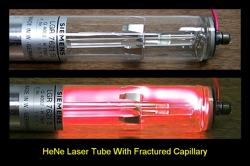
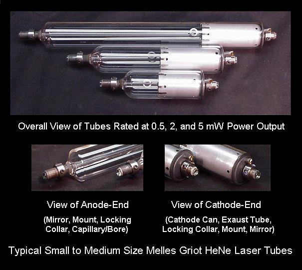
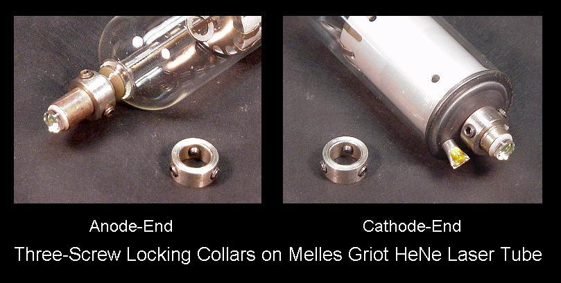
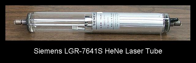
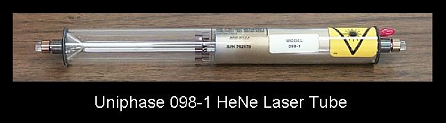
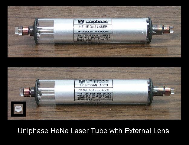
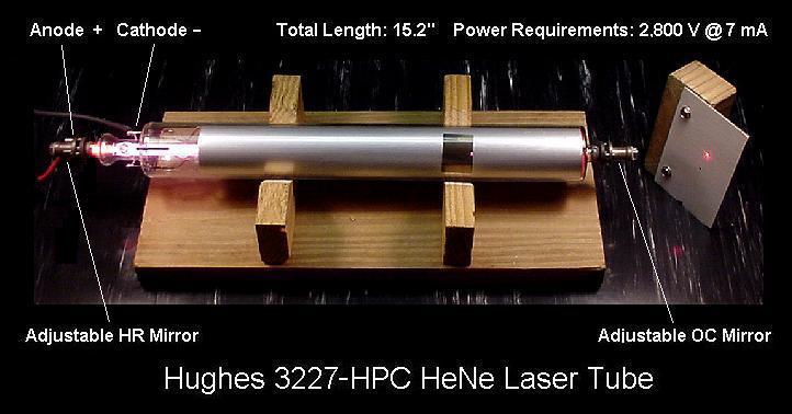
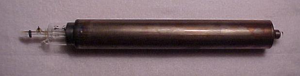
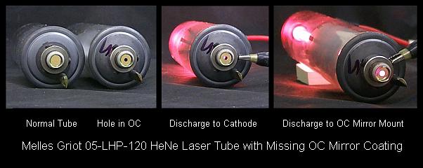
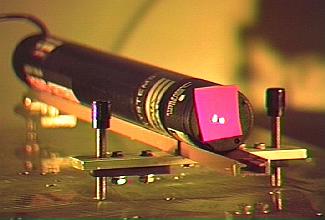
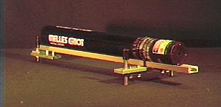
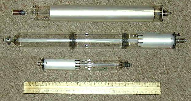