Although one of the simplest in basic structure, given these requirements, the HeNe laser may not be the best home-built laser for the novice. However, later in this chapter, we present a number of alternatives to the HeNe laser fully built from the ground up using beach sand and copper ore. Therefore, it is still possible to experiment with partially home-built HeNe lasers (beyond just wiring together a HeNe tube and power supply) using various proportions of your own ingredients without doing everything from scratch. :)
Take precautions to avoid eye contact with the direct or reflected beam, whether or not it is visible. This includes the 4 pairs of beams reflecting off the Brewster windows which may be quite strong.
See the section: HeNe Laser Safety for more info. However, the home-built HeNe laser uses a different sort of power supply than CW commercial types (unless you are attempting something similar to one of these) so some of the specific details may not apply,)
For more information, see the chapter: Laser Safety and the more specific information in the section: HeNe Laser Safety. Sample safety labels which can be edited for this laser can be found in the section: Laser Safety Labels and Signs.
If anyone reading this has built (or even attempted) a HeNe laser from scratch, please send me mail via the Sci.Electronics.Repair FAQ Email Links Page!
(From: Mark Wilson (wilson_mark@htc.honeywell.com).)
"When I saw the Scientific American article on building your own HeNe laser, I decided that I wanted to build it. The Scientific American HeNe laser was extremely difficult to build and I could not have done it without a lot of help. I got Spectra-Physics to donate a set of laser mirrors to me, a glass shop in my home town to help me cut and grind the Brewster window angles on the tube. The tube was made from lead glass from a sign company, and I also used neon sign electrodes. The optical rail was a 3 foot long piece of 2"x6" extruded aluminum that I got from a glass company which used this material to make doors for commercial buildings.I followed the directions in the Scientific American article to the letter. I sealed the microscope slides to the glass tube using flexible colodian that I got from a pharmacy. I filled the tube at a sign company which had He, Ne, Ar and other gases on a glass manifold. I assembled the laser and made the power supply using a mercury rectifier tube and a neon sign transformer. I got the tube to lase for a brief time, but since it was not a hard-sealed tube it quickly died probably due to helium diffusion. The tube would light up but not lase for a while then that too stopped."
Refer to Typical Home-Built Helium-Neon Laser Assembly for a simplified diagram of the overall glasswork and power supply electronics.
Operation at wavelengths more than a few nm away from 632.8 nm (except possibly for 640.1 nm) would likely require changing the mirrors to have their reflectivity peak at that wavelength (unless they are very high reflectivity broadband coated), and using the appropriate angle for the Brewster windows (or implementing an adjustable Brewster angle as described in conjunction with the Home-Built Pulsed Argon and/or Krypton (Ar/Kr) Ion Laser Laser).
       H o----------+ T1                T2   +---------o HV AC
                     )||               ||=||(
              Variac )<--------------+ || ||(
              0-115V )||              )|| ||(
                  5A )||    Neon Sign )|| ||(       Well insulated
                     )||  Transformer )|| || +---+  HV wires to HeNe
                 +--+        9kV,18mA )|| ||(    |  tube electrodes
                 |                    )|| ||(    |
       N o-------+-------------------+ || ||(    |
                                       ||=||(    |
                                       |   | +---|-----o HV AC
                                       |   |     |
       G o-----------------------------+---+-----+
                                                _|_
                                               ////
However, there are two disadvantages to using a narrow bore:
I would recommend a one piece approach instead, with a thick-walled capillary fused directly to glass extensions (as used in the Vander Sluis et. al. paper) if your glass working skills and/or budget are up to it (or glued to metal extensions if using the no glass working approach).
No other aspect of the laser tube assembly itself is as important as the quality of the Brewster windows to the ultimate outcome of this project! While, certain types of distortion won't prevent lasing (some may even make it more exciting with complex mode structures), this is a complicating factor your first laser can do without.
The author of the SciAm article suggests the use of quartz instead of glass to minimize heat losses but that material has a high transmittance at the 3.391 um IR wavelength which interferes with operation at 632.8 nm (and other visible wavelengths). If you insist on quartz (perhaps to have the option of 3.391 um operation in the future), also obtain a pair of glass flats to add outside the tube to kill that line. If you do try lasing at 3.391 um, aluminum mirrors should be fine. This line will even lase with no mirrors (superradiantly) in a long enough tube.
CAUTION: Apparently, it is possible for an electron beam to be produced from the positive electrode during the high current bake-out step which can quickly melt a hole through the tube wall opposite the side-arm if left running for more than a few seconds. The visual effect will first be a spot of bright yellow sodium light from the point of impact. Use lower current and/or make that area of the tube (the outside of the turn) much thicker.
(From: George Werner (glwerner@sprynet.com).)
"I have read with interest your wealth of information on home-built HeNe laser because every problem you dealt with was one that we grappled with about forty years ago. I was a member of a group here in Oak Ridge that built the first HeNe laser in Tennessee about six months after Bell Labs announced the construction of theirs.Back in the 1960's we had a laser development group that decided that before we came out with a new kind of laser we should get laser experience by building one (HeNe) like Bell Labs. Ken Van der Sluis was the principal investigator. His prior experience with resonators was with the Fabry-Perot (FP) interferometer, so much of our construction was adapted from FP construction. The reflectors were 5 cm diameter in mountings that used 1/4 - 80 threads on the adjusting screws and Invar rods to maintain spacing, a case of overkill on every turn.
The finest window material we had were quartz FP flats 5 cm diameter x 1 cm thick, and these were cemented onto the Brewster-cut tube ends. Ken was measuring gain with a spectrometer, adjusting mirror angles, gas mix, gas pressure, and discharge current, trying to find the magic combination but with no luck. Then Ken realized that it was possible that the infrared transition at 3.391 um was depopulating the upper level of the transition we wanted to use. After adding a borosilicate crown glass (BSC) flat (which blocks 3.391 um) to one of the windows with masking tape, and some realignment of the mirrors, it wasn't long before he got the first spark of red light - the first HeNe laser light in Tennessee! Soon word got around and for the next day or two we had dozens of visitors to see this fascinating red sparkling light. (It was our opinion that Bell Labs did not know about the 3.39 um trap and that they were lucky to have tried BSC first.)
The lasers we made were made to get that sparkly red light and we were not concerned about the mode structure (except for our theoretical physicist who was fascinated by all the different multi-mode patterns we could get with our wide bore tube and he had names for them all). In fact, we soon abandoned using thick Brewster windows with optically flat surfaces, and sometimes used ordinary microscope slides.
This work led to our development of a demonstration laser which we took to universities and a few high schools mostly over the eastern United States, and also to South America and Hungary.
Everything can be found in the paper: "A Simplified Construction of a Helium-Neon Visible Laser", by K. L. Vander Sluis, G. K. Werner, P. M. Griffin, H. W. Morgan, O. B. Rudolph, and P. A. Staats in the American Journal of Physics, vol. 33(3), pp. 225-240, March 1965.
(Here is another paper from the same group at Oak Ridge National Lab that should probably be in another chapter but I put it here: "Conversion of a Simplified HeNe Gas Laser to Pulsed Operation with Ar, Kr, and Xe", H. W. Morgan, P. A. Staats, P. M. Griffin, G. K. Werner, and K. L. Vander Sluis, American Journal of Physics, vol. 37(9), pp. 938-939, September 1969. --- Sam.)
My most important contribution to the effort was that I was the inventor of the Laser Alignment Card, which you allude to later in this chapter. I could go on for several pages talking about lasers. We old-timers love to talk and reminisce!"
(George has since gone on for several pages talking about lasers and has contributed several sections relating to the home-built HeNe laser, amateur laser construction in general, and other laser topics.)
The HeNe laser presented in the paper is very similar to the SciAm design which isn't terribly surprising given that it was published in the same time frame. A photo in the paper shows the minimalist approach to laser design - the laser tube as well as the resonator mirrors supported by chemist's burette clamps on wobbly ring-stands with a Tesla-type leak tester for excitation! Well, maybe. Some of may partially home-built laser test rigs were a lot less stable. :) OK, this isn't what they recommend building (or what is described more fully in the paper and below) but it was included to drive home the point that you don't need a lot of sophistication to construct a working laser.
I really liked the suggested supplier list (with 1965 prices!) which was thoughtfully included with my copy of the reprint of the paper. Optical windows for 25 cents; 1 liter flasks of He:Ne gas mixture for $6.50, and (small) neon sign transformers for $9.95. If only these companies were still n business today (using those same prices)! What I would give for a working time machine. :) One interesting thing is that while some items were quite inexpensive (if inflation wasn't taken into account), the dielectric mirrors were priced quite high - after all, this was new technology! And similarly, semiconductor rectifiers, which are dirt cheap today, were 10 or 20 times as expensive in 1965 dollars - much much more if inflation is included.
There is one piece of information that can be inferred from the paper that is lacking from all of the SciAm articles: The actual optical power output. Based on their use of a silicon photodiode detector, I expect that it peaked in the .5 to 1.25 mW range depending on gas fill ratio and pressure. This assumes a photodiode current sensitivity of .4 to .5 mA/mW. Note that this was with mirrors that were about half as efficient as modern ones (they had significant absorption losses) and they were both OCs so an equal mount of power exited both ends. Thus, it would appear that up to about 5 mW may have been possible by using a modern HR/OC pair. Maybe I could use that time machine to take them a set. :)
Here is a description of the HeNe laser presented in the paper summarized in my standard format. Some of the dimensions below were estimated as there is no dimensioned drawing in the paper. The authors suggest a variety of possible modifications as well. While the title of the paper implies a simplified approach, the authors did have access to a decent machine shop (including lathe and diamond cutoff wheel) and glass working shop (the glass fabrication looked perfect). However, like the SciAm lasers, this really isn't essential.
                                             D1       R2       Rb
 H o-------+ T1                T2   +-----+--|>|--+--/\/\--+--/\/\--+--o HV+
            )||               ||=||(      | 10KV  |25K 20W |        |
     Variac )<--------------+ || ||(      |      _|_ C1    |        |
     0-115V )||              )|| ||(      |  R1  --- .25uF |        v Spark gap
         5A )||    Neon Sign )|| ||(      | 170   |  2KV  _|_ C3    ^ 4KV
            )||  Transformer )|| ||(   +--|-/\/\--+       --- .1uF  |
        +--+        3kV,54mA )|| ||(   |  |  5W   |  C2    |  5KV   \ R7
        |                    )|| ||(   |  |      _|_ .25uF |        / 50K
 N o----+-------------------+ || ||(   |  |      --- 2KV   |        \ 10W
                              ||=||(   |  |  D2   |        |        |
                              |   | +--+  +--|<|--+--------+--------+--o HV-
                              |   |         10KV
 G o--------------------------+---+
                                 _|_
                                ////
As noted, T2 is actually three, 3 KV, 18 mA, neon sign transformers wired in
parallel to obtain the 54 mA current rating. Rb, the ballast resistor,
consists of 4, 25 K, 20 W resistors in series with taps to adjust the tube
current.
Note that the voltage ratings of C1 to C3 are marginal at best. Should the spark gap fail, the output voltage could easily climb to nearly 10 KV.
A modern tube with a 34 cm discharge length would be rated about 5 mW when run from a normal HeNe laser power supply (DC, constant current).
For an HeNe tube, a wider bore doesn't necessarily permit higher power since the walls of the capillary apparently are important in depopulating higher energy levels. Gain actually decreases (inversely) with increasing bore diameter. I will assume that this is really equivalent to a 1 mm bore in a modern tube (and this may be optimistic).
Loss factor: .5.
Loss factor: .5.
Loss factor: .5.
Loss factor: .5.
Based on these considerations, I would be surprised if the original design produced more than .5 mW. But the good news is that it might be possible to approach 2 or 3 mW without too much effort using a narrower bore, large can style cathode, and modern HeNe laser power supply.
The very similar design described in the Verder Sluis et. al. paper (see the section: K. L. Vander Sluis et. al. HeNe Laser), had a maximum power on the order of 1 mW under optimal conditions based on their measurement of power using a silicon photodiode. So the wild guesses aren't all that far off. :) (However, it may have been capable of as much as 4 or 5 mW using a modern HR/OC pair.)
The SciAm article recommends using quartz windows because they have the lowest losses. We thought the same thing back in 1963 when we were trying to build a laser like the one that had been demonstrated by the Bell Labs people a few months earlier. Ken Vander Sluis had built our laser with two of our best quartz Fabry-Perot interferometer plates and was trying for days to make it run, with no luck.
Ken is a spectroscopist and understands how energy levels work, so he thought about it, and reasoned that the 3.391 um transition might be depopulating the upper level so that the visible transition wouldn't lase. For the 3.391 um wavelength, quartz transmits well, but borosilicate and other glasses do not. He got another pair of interferometer plates, made of borosilicate crown glass, and put them over the quartz plates, fastening them in place with masking tape. After realignment he found an increase in gain and before long he got that first sparkle of light, the first HeNe laser in Tennessee!
So the moral of the story is: Don't count on quartz windows giving you the best performance. "But", you may ask, "What about those lasers with no Brewster windows?" I have never measured their reflectance, but my guess is that the mirrors must have a multilayer surface that was designed with two criteria: high reflectance at 632.8 nm and low reflectance at 3.391 um.
Even with glass Brewsters, the 3.391 um effect rears its ugly head in long lasers, those with length of one meter or more. In these the path length in the plasma before encountering a window is long enough that the 3.391 um density has a chance to build up to undesirable levels before meeting a window. It's called "superradiance" and can be suppressed with magnets (preferential Zeeman splitting of the IR lines) and/or by grinding the inner surface of the tube to scatter low-angle reflected light. But, tubing with a roughened interior is not as strong as standard tubing.
(From: Sam.)
Yes, that is exactly how they are designed. With sufficiently high transmittance at 3.391 um and possibly the frosted bore as well, the need for magnets to split the energy levels via the Zeeman effect has also been reduced or eliminated. For example, even the Melles Griot 35 mW HeNe laser (their largest model) does not need magnets even though the tube is almost a meter long.
The alignment is performed with the laser powered but presumably not lasing since a 'spoiler glass' - a glass microscope slide - is placed in the optical path. While this probably is fairly reliable with minimal risk for the low gain HeNe laser described in the article, many other lasers - or even a longer HeNe laser - may have high enough gain that the losses introduced by the spoiler would NOT prevent lasing and a beam could appear without warning (once the mirrors are aligned well enough) as the adjustment screws are being tweaked! I would NOT recommend the procedure as described for any laser unless a more reliable method were used of preventing accidental lasing (like the use of a 50 percent neutral density filter) or you were absolutely sure of the maximum possible output power of your laser to be less than a couple of mW. Note that even with a spoiler, there is still a slight chance that a HeNe laser will lase if the glass is nearly perpendicular to the optical axis (due to constructive interference of the reflections from its surfaces). A neutral density filter would totally eliminate even this small possibility.
The description as presented is also somewhat ambiguous (but this is clarified below).
Note that if you don't have 20/20 (corrected) or better vision, this procedure may not be appropriate in any case since for the fine alignment, it's necessary to view the reflection from the mirror at the far end of the laser through its narrow bore - not easy with less than perfect eyes.
I would recommend using one of the other alignment techniques described in "Light and its Uses" or in the chapters of this document on HeNe and Ar/Kr lasers.
Having said all that, I am honored to have George Werner, the inventor of the this alignment technique while at Oak Ridge around 1963, address the safety issues and provide a clearer description of the procedure:
(From: George Werner (glwerner@sprynet.com).)
(The alignment card technique may have been independently invented elsewhere.)
First, the matter of safety. If you are looking through the alignment card at the time the laser starts to oscillate you will see a very bright light, but it won't be the last light you ever see. Have you ever looked at a camera flash bulb when it went off? Have you ever looked at the sun? These sources are too bright for normal viewing so nature gives us a defense for it - - we close our eyes immediately. As for the laser's brightness, the first burst of light, if adjustments are made slowly, is much less than the maximum output. Even this exposure can be avoided, as I will discuss later.
The alignment card I have used most recently has a hole about 2.5 mm in diameter. If you're worried about exposure you can make it smaller but that makes precise seeing more difficult. (In our report by Vander Sluis et al, we used .5 mm) The card stock is preferably heavier than normal filing cards, but they will do. The hole is made by drilling to ensure a round shape, but this leaves paper fibers protruding into the hole, which can be made to lay down by polishing the inner edge of the hole with wax or maybe glue. On the front side carefully rule a horizontal and a vertical black line across the hole. It is important that the intersection of these lines be on the hole, and sometimes I think that is easier to rule the lines first and make the hole afterward. A piece of a red gelatin filter, Wratten #29, is mounted on the back side of the hole. I have stuck it in place with a 1/2 inch circle of black masking tape with a 1/8 inch hole in it. Having an area of black around the hole as viewed from the back makes it easier to find and look through. In the deluxe model of card I use a fluorescent red surface on the front instead of white.
The card is used in this way: Position the card at one end of the laser, viewing through the near reflector, so that you can sight through the card hole and through the capillary to the far end. (To facilitate this it may help to place a strongly illuminated target beyond the end of the laser. The fine print on the back of a credit card is good for this purpose.) Holding the alignment card in this position, observe the crosslines as reflected from the back side of the reflector and adjust the reflector so that the pinhole image lies on the capillary axis. Now the adjustment at the near end is complete (we hope).
Next, take the card to the other end and repeat the operation. Note that at no time up to now has the laser been turned on so your eyes should be perfectly safe. NOW turn the laser on and it will shine with all its brilliance (it says here). :)
If, however, the laser doesn't lase, make another inspection of the adjustments. This is where the red filter is needed. If you try to sight down the capillary while the laser is turned on, all you see is a cloud of blue light if you don't have a red filter. One experimenter reported the red filter was ineffective. I suspect that he wasn't using a Wratten #29. The red cellophane from a box of Valentine candy won't work. It passes too much yellow. With a proper filter you can easily see to the far end of the tube through the luminous plasma. With the laser turned on, look through the card and plan your next adjustment of the mirror but don't make it. Then move your eye away from the pinhole and make the adjustment you planned. If it doesn't lase, you can look through the pinhole and repeat the motion to see what is happening at the far end of the tube. If your system is geometrically correct but still not lasing, you will see a brighter (but not brilliant) disc of light coming into position at the far end as the final adjustment is made. This is what is commonly called the "full moon" effect. If that bright spot is well centered when viewed from either end, then you can be assured that no further mirror tweaking is called for and you can turn your attention to gas pressure, current level and all those other problems.
I mentioned the use of a red fluorescent alignment card. What is the advantage of that? The only useful light reflected from a white card with red filter is the red component of the illuminating light. A fluorescent red card reflects the same red light but it also converts the blue, green and yellow light to red, giving us a brighter image.
I haven't found a laser where it was not possible to see the far end of the tube looking through the card. Maybe the sighting hole was too small (like 1 mm or less) or maybe there was fuzz in the hole, or maybe as I have said before the filter wasn't red enough.
In a very long narrow tube it is sometimes hard to determine straightness because internal reflections of a curved tube can give false images of the end opening. The curvature of the tube focuses the light in one plane, while at the same time in the other plane the strong focusing power of the bore radius is decreased at grazing angles, so that there is a curvature for which the reflected image has no astigmatism. Once I made a little light box to use as a target for this test. In front of a 15w light bulb I placed a wire screen mounted on a motor shaft to turn 6 rpm. I set it so that the target was moving left to right. Then if I looked at it through the capillary and saw an image moving right to left I knew that I was looking at a reflection.
When you have confirmed good alignment and the windows are clean, you may wonder if the gas mixture is right. In lasers that have been sealed a long time there is sometimes a noticeable loss of helium by diffusion through the glass and through the Epoxy of soft-seals. A good way to check the He:Ne ratio is to view the discharge spectroscopicly. I used to use a transmission grating (600 lines/mm) for this. In the yellow region you will find two lines close together. These are neon, 585.25 nm, and helium, 587.56 nm. If the mix is right these two lines should appear equal in brightness.
For a sealed tube, the helium lost by diffusion can be restored by putting the laser in an atmosphere of 100% helium (at 1 atm) for a day or two. 24 hours of inward diffusion this way is about equal to the outward diffusion of a year. (See the section: Rejuvenating HeNe Tubes.)
I do have a working green HeNe laser using a special one-Brewster HeNe tube with an HR optimized for green and a matching HR mirror. OK, so the output isn't anything to write home about - maybe a uW - but the circulating green photon flux is fairly impressive. However, this setup is just about perfect in every way with an optically contacted fused silica Brewster window and super high reflectivity mirrors for both HRs. See the section: A Green One-Brewster HeNe Laser for details. But it's amazing that such a short (26.5 cm) one-Brewster tube will lase green at all!
Also see the section: More on Other Color HeNe Lasers.
(From: Steve Roberts (osteven@akrobiz.com).)
From a letter in the IEEE Journal of Quantum Electronics by D.L. Perry, inventor of the green HeNe laser:
"Green #1 used a 65 cm long, 4 mm ID tube with a 7:1 fill ratio of He:Ne. Both optics had a 1% transmission at 594.1 (yellow) to kill that line. The current range was 16 to 40 mA (!!).The 611.8 nm (orange) line was used to align the laser (using red/orange optics). Then the green HR mirror was installed in the beam to align it and then the red/orange optics were removed."
He obtained a power of 50 uWatts with this setup.
(From: Sam.)
Hey, but that's still much greater than the output power of that green one-Brewster HeNe laser and also greater than the output power of my red two-Brewster HeNe laser described in the sections starting with: Sam's DIY External Mirror HeNe Laser - Some Assembly Required!.
Yes, it's possible because I have done it. The trick is to mill or saw a 1/2 inch aluminum plate to hold the window at 56 degrees to the axis of a hole you drill through it to receive the small bore laser tube. A side hole connects with this hole into which is glued a nipple for attachment to a vacuum system. Drill and tap a 6-32 hole somewhere for a screw to attach a wire because this piece is also an electrode. The one I made had a few extra square inches extending below so that I could put it in a beaker of water to dissipate the heat from the electrode. The allowable temperature of the aluminum is limited by the heat tolerance of the Epoxy you use to glue it together. Mine was a DC laser so only one end (the cathode) needed to be this large.
A photo of that part of the tube is shown in Cathode-End of Home-Built HeNe Laser Requiring No Glassworking. The aluminum block cathode and negative power supply lead can be seen with the Brewster window glued to its angled surface. The glowing bore of the tube extends toward the upper left corner. For scale, the platform is 3 inch aluminum channel and that's one of my early (white) alignment cards in the lower right.
The anode was similar but without the heat sink and vacuum attachment. Keep the kids away from it and/or make arrangements to insulate the high voltage electrode electrically but not thermally.
(From: Sam.)
Sputtering at the negative electrode would be my other concern. If it is near the Brewster window or internal OC mirror, a metal coating could form quite quickly, rendering the laser useless. I would recommend locating the cathode a few inches away - perhaps it could be a second aluminum block or an aluminum tube attached to the end of a glass side-arm glued into the block described above. The advantage of this geometry is that there is no direct line-of-sight path to the optics and thus sputtered material is much less likely to land there. Putting a few heat sink fins on this should provide adequate cooling if it becomes more than warm to the touch.
Even simpler: Use common pipe fittings at each end, one being a "T" for a side-arm mounted glass extension to which the aluminum cathode is attached.
(From: George Werner (glwerner@sprynet.com).)
Here is a laser design that I planned 35 years ago but never built. If you want to try it out you are welcome to it.
If one wanted to make a really long laser, one way to keep the 3.391 um radiation suppressed would be to stick a glass (not quartz, remember?) Brewster window in the optical path every 50 to 100 centimeters. Also, if we want to maintain the conditions of a conventional laser, we need to refocus the light rays periodically along the length. So the Brewster thing needs to be a lens rather than just a window. But a lens tilted to 57 degrees would have terrific astigmatism. OK, then have the window start with a reverse astigmatism such that when tilted to 57 degrees the astigmatism vanishes. Or, use a normal lens that is AR coated. If the AR coatings are really good then tilt should be unnecessary. (Note that the standard formulas for reflectivity won't work at an AR coated surface - I don't know if there is a Brewster angle for an AR coated surface.)
The change in focal length from tilt is a relatively simple matter for concave reflectors (cosine for one direction, 1/cosine for the other), but for lenses it is more complex. I did a rough check on focus of a tilted lens at 0, 30, and 60 degrees and it showed that the focal distance (can we still call it focal length?) is the original focal length times the square of the cosine of the tilt angle for focus in the plane of the tilt and times the square root of the cosine of the tilt angle in the orthogonal plane. Then I did some more exact ray measurements on the computer and instead of cos2. I found it was closer to cos2.55. (Close, but not exact). I contemplated computing the focus in the other plane but decided that was too much bother since I don't even know if anyone is going to read this. (Well, read?, yes; build?, hmmm. --- Sam.)
Therefore the lens/window, if it is to have a tilted focal length of 50 cm, should have a conventionally-measured focal length of 220 cm in one plane. and 67 cm the other way. The practical way to get such a lens is to deal with a manufacturer of spectacle lenses, so we have to translate to diopters and round to the nearest 1/8 diopter. Thus we end up with a refractive power of 0.50 diopters in one direction and 1.5 diopters in the other direction yielding tilted focal lengths of 45 cm and 50 cm (close enough). I guess the optometrist would call for "sph. +.50 , cyl +1.00". Make sure your lens maker understands that these curvatures are relative to a flat surface on both sides, or you may find you are given a lens that is strongly concave on one side as in standard spectacles. Perhaps each surface should be described as sph +.25 , cyl +.50. Check with the lens man.
After having one made and checking it out, order as many as you want for your laser. Each section has its own power supply and glass system (with a shared window) and they can be tested and added one section at a time. The completed design as I see it is a multiple confocal system with end mirrors of 100 cm radius and intermediate lens/windows with 50 cm focal lengths every 100 cm. The windows nearest the mirrors are flat. When testing an incomplete assembly the second concave mirror should be 100 cm away from the last lens/window.
In my imaginary design of this laser, each section has a glass ball joint near a window so that each section can be adjusted to be collinear with the rest, but I can also see it running as one huge glued-together contraption. After enough sections are added, it should lase without a terminating mirror, and this suggests that by that time it would have lost coherence. Who'd like to predict how much power it will produce? Who'd like to predict what limits the power?
The following sections describe various ways of ending up with a working HeNe laser that don't require quite as much in the way of support equipment and supplies as building one from the ground up. These include morphing a commercial HeNe tube into a home-built HeNe laser, using commercial one and two-Brewster HeNe laser tubes with your own resonator, and even a way of converting a cheap barcode scanner HeNe tube into a precision frequency stabilized laser. While perhaps not quite as rewarding as doing everything from scratch, the likelihood of success, particularly with the latter approaches, is much much greater.
Taking an existing HeNe tube and using it as the foundation for an external mirror laser would eliminate some of the hassle of constructing everything from scratch. Specifically, most glass work would be eliminated and by doing things in stages, the risks are somewhat reduced.
If you don't want to even think about vacuum systems and gas supplies, HeNe (and Ar ion) plasma tubes with Brewster windows for use with an external cavity ARE available from various sources. With one of these in-hand, and a matching conventional power supply (commercial or home-built), you can still experience the joy and frustration of constructing and aligning an external mirror laser head. I've even gotten lasing from a HeNe tube with a damaged OC mirror using an external mirror though I doubt there is another similar tube in the entire Universe so perhaps that isn't quite fair. :)
It then is *just* a matter of fabricating the laser platform and mirror mounts, and obtaining a pair of suitable mirrors. There would be NO excuse for failure!
However, the problem is that since such tubes are a lot less common - and mostly used as replacements in expensive high quality research lasers, their cost is considerable. Figure $600 to $1,000 or more depending on quality, size, and supplier. Check out the large well known HeNe laser manufacturers. Perhaps, if you can convince them it is for an educational project, they might let you have one that doesn't quite meet their specs for free or at cost.
Perhaps, after successfully constructing a laser head in this manner, you will have the confidence to proceed with a totally home-built design. The continuing saga of my (so far less than entirely successful) experience with this approach follows in the section: Sam's DIY External Mirror HeNe Laser - Some Assembly Required!.
The opposite situation is also a possibility: Build your own HeNe plasma tube but mount it in a used resonator. Depending on your resources, this might be an easier task (though I find that hard to imagine!). External cavity HeNe laser heads with dead tubes seem to turn up much more frequently than the other way around (for obvious reasons) and can often be obtained at attractive prices. In fact, the dead tube one of these contains might be a candidate for regassing!
You will need the vacuum setup and a source of the HeNe gas mixture, but the serious glass working can be postponed for another day.
The basic idea will be to start off with a laser resonator that once worked (a commercial HeNe tube) using a regular HeNe laser power supply. Inexpensive HeNe tubes and power supplies are readily available and therefore, much of the uncertainty can be easily eliminated so you can concentrate on the gas and vacuum issues.
I would recommend something in the 5 to 10 mW range - large enough to be interesting but not so long as to possibly require magnets or other special attention to operate reliably.
WARNING: The anode will be at a kV or more with respect to everything else! Cover, shield, or otherwise insulated it from accidental contact.
WARNING: Where this fill port is attached to the anode as is likely, not only must you take extreme care in working with anything connected to it, but there will have to be a long narrow gas flow path to prevent the high voltage from striking between the tube anode and the gas supply cylinder instead of the tube cathode. Even if your gas supply system is electrical isolated from ground, its large capacitance to free space would make powering the HeNe tube difficult.
Note: For this to work, both mirrors must be planar (which is difficult to align especially for a long narrow bore resonator) or must have a focal length significantly longer than the original tube length - otherwise, the added distance between them when mounted externally will mess up the cavity relationship that would have been present where one or both was concave.
In addition, it is almost certain that the reflectivity of the Output Coupler (OC) mirror - the one at the output-end of the laser that were part of the HeNe tube in the first place - will be too low for anything approaching optimal performance (and perhaps not even have enough gain to lase at all) once the losses through the Brewster windows are taken into account (especially those that aren't perfectly clean, high enough quality, and not exactly at the correct angle). Therefore, higher reflectivity optics for the OC with a curvature optimized for an external mirror HeNe tube similar in length to your creation should probably be used from the start to avoid a lot of frustration.
Note, however, that for clean, fused silica, very flat Brewster windows set at the proper angle, losses can be very low and even short one-Brewster HeNe tubes (e.g., 10 inches between HR and Brewster window) have enough gain to lase easily with quite low reflectance OCs (e.g., 97 or 98 percent - typical of the OCs in 25 to 30 inch internal mirror HeNe tubes. So, you may get away with using the original OCs if your Brewsters cooperate. :)
Another option is to forgo red entirely until you have something that lases at all and go for one of the IR lines: 1,162.3 nm, 1,523.1 nm, or 3,391.3 nm. I may be easier to get a short tube to opaerte - even one that won't work at all for red, especially at that last one - which will even lase superradiantly (without mirrors) in a moderate length tube. Of course, suitable optics will be needed as well as some means of detecting the IR. A silicon photodiode, CCD camera, or IR detector card can be used for the 1,162.3 nm wavelength; a phosphor plate or something else for the longer ones. Take special care if you do this as the IR is, of course, invisible, but can still cause eye damage. Personally, I'd go with the red - it's challenging but doable.
One possible inexpensive or free source for high quality Brewster windows is a defunct external mirror HeNe tube - but if you had one, you would probably be using that to build this apparatus entirely! Another possibility is a dead one-Brewster HeNe tube or a Hughes style polarized HeNe tube (which may actually be a one-Brewster HeNe tube with an external OC mirror glued to its Brewster stem). See the section: Determining Brewster angle.
Or, to keep the mirrors intact and mounted, use a file to score around the thin section to the point just before the metal is penetrated. Snap off the mount and immediate cap the end(s) of the tube to minimize the possibility of contamination. Don't remove the mirror glass from the metal mounts - they are more convenient to handle. Put each mirror/mount in s little plastic bag and set them aside in a tightly capped container until needed. (Even if, as recommended, you start with an OC mirror designed for use with an external mirror HeNe tube, after you get the thing lasing, you can go back and try the original OC to determine if it will work at all.)
If you really want to experiment, are doing this with an HeNe tube that was originally 30 cm or longer, and have a high frustration threshold, obtain a set of mirrors designed for an 'other color' HeNe tube and see if you can get something other than coherent red light from your contraption!
Note that even getting a short external mirror HeNe laser (e.g., bore length less than 30 cm or so) to operate on the red 632.8 nm wavelength may be difficult unless everything is perfect. And, there aren't that many commercial external mirror HeNe lasers in 'colors' other than red or IR - the gain is even lower than for red on the orange, yellow, and green lines so losses must be cut down to as near zero as possible! The very slight reflection from even high quality Brewster windows may be enough to prevent lasing unless the bore is long. Hint: Green has to lowest gain of the common 'other HeNe colors' so I would suggest avoiding that, at least until you have succeeded at yellow or orange! :)
You can use a pair of identical electrodes and the AC power supply described in "Light and its Uses". However, it would also be possible (with just a little more glass-work) to provide a large side-tube (which also provides a much greater gas reservoir) and aluminum (can) cathode as in commercial tubes with a regular HeNe (DC) laser power supply.
I have had a 30 inch long HeNe laser tube with a broken-off OC mirror (from overzealous attempts at alignment, don't ask!) sitting in a box in the attic for a couple of years now. It never really worked quite right anyhow with erratic power fluctuations and didn't come anywhere near its 20 mW rating even when all the planets were precisely aligned. :) The cause is unknown - possibly low gain due to a contaminated gas fill resulting in low gain. This tube seemed like it would be ideal for creating a nice long semi-home-built one-Brewster laser. And, I wouldn't feel at all guilty about making irreversible modifications - no chants or incantations required for the "gods of dead lasers" either! ;-) The HR mirror is known to be in good condition and properly aligned and there is a nice hole where the OC mirror used to be (the OC has since been reassigned to other projects and works fine so the tube's original problems weren't due to the OC). The exhaust tube is nice and long (about 3 inches) - apparently, this tube never actually was totally completed. It is also one of those peculiar HeNe tubes described in the section: Segmented HeNe Tubes. I expect this to be an advantage since the gas reservoir ends up being distributed throughout the bore and there should be less 'pumping' of gas from one end to the other by the current in the discharge. (Since I have a couple of other more normal tubes from the same source that also experience the lack of power and instability, I don't believe that is related to the segmented design.)
A diagram of the proposed assembly is shown in Sam's One Brewster Helium-Neon Laser Tube Conversion.
To accommodate my mediocre vacuum system, I intend to construct this as a flowing gas system. So, I will drill a hole for the gas fill port in the end-plate at the anode-end of the tube (the exhaust tube is, as usual, at the cathode-end) and attach a piece of metal capillary tubing to it with Epoxy.
I will attach the well cleaned Brewster stem salvaged from a Hughes style one Brewster HeNe tube to the OC mount stump. Although the diagram shows a sleeve and Epoxy seal, I may use a threaded pipe fitting so that the Brewster window can be easily removed or replaced if needed, or some other optic like an OC mirror could be substituted if desired. For initial testing, I have installed a piece of clear plastic tubing and a pair of small pipe clamps. This probably won't retain a decent vacuum but should work for flowing gas operation. And, the angle of the Brewster window can be adjusted if needed!
The external OC mirror will be mounted on an adjustable plate with everything attached to a rigid base.
My SP-255 exciter on a Variac should be satisfactory for powering this laser.
To be continued....
I acquired an external mirror HeNe tube for this exact purpose. Physically, the body of the tube looks like a Melles Griot internal mirror type (but no manufacturer label). Probably the closest current model would be the 05-LHR-120 HeNe tube used in the 05-LHR-121 laser head which is rated at 2 mW. Additional info can be found in the section: Typical HeNe Tube Specifications.
However, instead of the normal mirror mounts and internal mirrors, it has a pair of Brewster windows. Although such HeNe tubes are manufactured for use in research lasers, I suspect this was a one-of-a-kind for another reason: In Magic Marker on the side is printed: He3, Ne22, 2.8, which I assume refers to the isotope of helium and neon used in the gas fill and the gas fill pressure (2.8 Torr). Ordinary HeNe tubes may use normal He4 and Ne20 so my guess is that this was manufactured for someone's thesis project with a title like: "Determination of How Lasing Spectral Characteristics are Affected by Gas Isotope". The consensus is that isotope differences will have only minimal effect - and this is supported by my measurements. See the section: Performing the Single Pass Gain Test.
Actually, having said that before I know what I was talking about (assuming I do now!), the upper energy state of He3 is slightly closer to that of Ne20 so energy transfer is more efficient and thus gain will be modestly higher for a given tube length. This is particularly critical for "other-color" HeNe lasers where every bit of gain is critical. But apparently, virtually all modern HeNe lasers, regardless of color, are now filled with He3. See the additional comments below.
Tubes with Brewster windows are available from several companies including Melles Griot and Jodon. Sizes from 10 cm to over 100 cm (between the centers of the Brester windows) are available which will operate at the 632.8 nm (red) HeNe wavelength. My funny tube has a length of about 25 cm so it is well within this range. This tube appears to be similar to a Melles Griot 05-LHB-290 Brewster tube except for the strange gas fill. Thus, if manufactured properly (e.g., with the proper Brewster angle and properly aligned windows), it should work!
For the resonator frame, I used some aluminum scrap from an old chart recorder and 9 track tape drive (Like the perverbial cow, I use nearly everything!). Low expansion InVar or something else equally exotic and expensive would be better, but given my machine shop or lack thereof, I would much rather deal with aluminum!
The mirror mount assembly consists of three parts: a fine adjustment plate, a coarse adjustment plate, and a small slotted adapter to which the mirror optic itself is attached.
The tube itself (henceforth called the 'Tube Under Test' or TUT) is mounted by a couple of aluminum brackets and Plexiglas plates with the anode-end on ceramic insulators. The ballast resistor is also mounted on the frame with a Plexiglas cover to prevent accidental contact with the high voltage terminals. There is even a HV Warning sticker - what a concept! Power is provided via a 4 foot HV coax terminated in a male Alden connector.
Once this was all constructed, I checked that it would power up and then evaluated the TUT for gain. See the section: Performing the Single Pass Gain Test.
This one in particular must have been dropped since the capillary had broken completely off of its attachment at the anode-end of the tube and was rattling around inside. Given this state of affairs, I would expect the "gods of dead lasers" to understand the need for the sacrifice since I could think of absolutely no way it could ever be made to lase again (but I did provide the appropriate chants and so forth just to be sure!).
After evaluating several options on exactly how to remove the mirrors (retaining various amounts of the rest of the tube), I decided to cut them off at the narrow section of the mirror mount. This would minimize the possibility of damage to the optics while at the same time providing a convenient metal collar to attach to my mirror mount plate. To minimize contamination, rather than using a hacksaw or file, I scored a line with a sharp pair of wire cutters and then snapped them off. Then, I cleaned up the rough edges with a file after stuffing a the hole to prevent the entrance of metal particles.
Well, since I pulled those mirrors off the little dead tube, I haven't heard of any global disasters so I guess the "gods of dead lasers" (GODLs) are satisfied with my chants. :) I did break a set of wire cutters trying to score a line (maybe that was my payment to the GODLs).
To mount the mirrors, I drilled a hole in each of my plates so they would retain their position by a press-fit. Then, with all the mirror mount screws tightened down, the plates with the mirrors were attached. To confirm that the mirrors were seated approximately correctly, I used my alignment HeNe laser to check for a return beam down the bore of the TUT. It didn't have to be exact (the coarse and fine adjustments will take care of that), but I wanted to be sure it wasn't really far off. A bead of Epoxy then assured that each mirror would stay in the proper position.
However, now I have 3 unknowns:
All the HRs tested at less than .1 percent transmission.
I know that I only have 2 percent to play with excluding losses through the Brewsters! So, these mirrors at least should be acceptable as long as the losses through the Brewsters are less than 1.3 percent or so. However, to have the best chance, I can just use an HR from another little tube (already have it so no need for sacrifices as someone else already went through that ritual) to see if I can get it lasing at all, then worry about the OC to get some power out at one end. Or, use Sam's special means of extracting power - a plate inside the cavity at almost the Brewster angle - 2 beams for the price of one! :)
(From: Daniel Ames)
Maybe my BEFIA (Beam Expansion for Interference Alignment Method) might come in handy with this one. (I guess that title sure could use some rewording, as the abbreviation sounds like a "beef processors union". :)
Important note: Be sure to offer the HeNe alignment chant, FIRST!
NOTE: This can be done with the same color HeNe, but the reflections will be substantially reduced in intensity. So, if using the same color R-Laser, (HeNe) use a bright fluorescent sticker or card for the viewing screen and dim the lights.
This procedure should only take a minute or two of your time, or forever. Your mileage my vary. :)
On your alignment jig, have you thought of any way other than the manual (slip and slide) method for lateral adjustment?
Geometrically speaking, it is much easier to move the TUT for aligning, than the reference laser. It works out to be a much less critical movement. The distance of movement of say 1/100th of a degree times the distance between the two lasers, is much greater than 1/100th of a degree times the length of just the TUT. It makes dialing in the alignment much easier, especially if the distance between the two lasers is more than the absolute minimum.
My (unorthodox) method:
It's reversed from the norm. I put the TUT on the alignment jig, and the reference laser was just positioned and secured at the approximate center of the jig's vertical and horizontal travel.
Although with my (unorthodox) method, the TUT still needs to somehow secured to the Jig.
Either way, what about putting a piece of metal, maybe aluminum, under the TUT for a smoother lateral positioning? Just a thought, maybe you already thought of this. :)
But I'm sure that you have a plan. :)
(From: Sam)
Right... I am quite convinced that alignment of the A-Laser relative to the TUT's bore really isn't a problem at this point.
I would have expected the reflectivity of the OC from that old laser to be similar to what was required for my funny tube because although its tube was (past tense, no longer intact) much longer, the bore was about twice as wide resulting in lower gain/inch. That OC is also curved which should ease alignment requirements. Unfortunately, I couldn't try the HR because it had been damaged. See the section: A Really Old HeNe Laser for a description of that laser.
However, there have as yet been no confirmed sightings of any flashes regardless of which optics were used, the phase of the moon, or wishful thinking. :(
At this point I am therefore left with 2 of the 3 unknowns: Absolute single pass gain of the funny tube and the curvature, quality, and cleanliness of the mirrors. Or....
I just noticed that there is some possibility that the funny gas fill with the non-standard isotopes of helium and neon might have been used to make this HeNe tube producing a green beam at 543.5 nm. See the section: More on Other Color HeNe Lasers. However, for all my tests, I have used red probe beams and mirrors designed to reflect red at 632.8 nm. Perhaps my problem all along is that I should have gone green!
After a pleasant interlude of getting a HeNe tube with a single Brewster window to work (see the section: A One-Brewster HeNe Laser Tube), I returned to this effort. I suspected that part of the problem was that I hadn't paid enough attention to the cleanliness of the Brewster windows. With the one-Brewster tube, even a single spec of dust or fine coating of who-knows-what could drastically reduce the output power. With two Brewsters, such effects would be much worse.
So, I went back to optics from the large-frame Spectra-Physics laser (and are what are shown in the photo, above). I hoped these would have the best chance of lasing short of a pair of long focal length HRs which I currently don't have. (The OC from the old lab laser might be even better if it has higher reflectivity - I may try that in the future.)
I discovered that by watching the scatter from the Brewster window closest to the alignment laser (A-Laser), it was possible to tweak the mirrors so that the spot caused by the beam from A-Laser and the return from the HR mirror at the other end of the tube could be superimposed. If this was done with the OC's reflection smack in the middle of the A-Laser's output aperture, there would be an increase in intensity and fluctuations in intensity due to mode cycling of the A-Laser and light bouncing back and forth between the A-Laser's OC and the OC of my resonator. At this point, alignment was really very close.
While gently rocking the mirrors I got what were unmistakable flashes for the first time. More cleaning and blowing off of dust and I was finally able to get a few photons of coherent 632.8 nm light coming from the funny tube.
Actually, a grand total of about 19 uW. (That's 19 whole microwatts - not milliwatts or megawatts!) It's a nice TEM00 beam - just not very bright! :)
Part of the problem may be that the inside of the Brewster on the cathode-end of the funny tube seems to have a lot of scatter - about as much as I get from the Brewster window of the one-Brewster tube with perhaps 100 times as much circulating light flux between the Brewster and the OC. How do you clean the inner surface of a Brewster window on a sealed tube? :(
Another and perhaps more significant characteristic is that when first turned on, the output power may be more than 2-1/2 times greater (more than 50 uW!!) and then decays to the lower value over the course of a minute or two. If it is turned off for a minute or two, the behavior will repeat. This could indicate a gas fill problem as I've seen similar behavior with an old Spectra-Physics 084-1 soft-seal HeNe tube. The mechanism would be that discharge current is causing the gases to be redistributed to the detriment of lasing gain or the optical power that can be extracted from the population inversion (sounds impressive at least!). The color of the discharge isn't obviously incorrect but could be a bit more pink than normal, though the spectrum appears normal. However, I may attempt to reactivate the getter in any case but this will have to wait until I get my induction heater working - there is no way to do this easily with my solar heater or by loading the entire laser into the microwave! However, I have tried the RF exciter test for gas fill problems and the results would seem to indicate that there is no detectable contamination.
I do believe at present that my OC reflectivity is marginal and I should be able to get a bit more power out of this tube by locating a mirror with 99.6% or greater reflectivity. As noted, I have tried a couple of HRs (which would certainly satisfy the reflectivity criteria) without even a single pair of coherent photons being ejected from the laser but since they originated from small internal mirror HeNe tubes, their focal lengths may have been too short.
Anyhow, this is success! I don't know how much more I can squeeze out of it regardless of optics but at least the entire effort resulted in a working laser - even if you do need to have someone point out the location of the beam!
I have left the two-Brewster laser as well as the A-Laser (just in case) set up against the back wall of my laser lab bench and turn it on from time-to-time just to be sure I wasn't imagining things. It continues to work at about the same power (or lack thereof) level, generally without requiring any mirror tweaking to peak it, only brushing off the Brewster windows.
(From Steve Roberts (osteven@akrobiz.com).)
You've got a research tube. And, being as short as it it, probably one designed for a single longitudinal mode. The foggyness on a hene is bad news... Do you get chaotic fluctuations as the mirror is moved slightly or if you put your finger on the tube? If so you have dirt in the path.
I suspect your tube was designed for spectroscopy games, or perhaps to be locked to a iodine or methane cell as a standards laser for metrology. Or maybe somebody was redoing the isotope work to see if anybody missed something.
Your best bet on the isotope thing is to contact Spectra Gases and ask them what isotopes they sell in the hot HeNe mix.
The following excerpts is from: "Laser Fundamentals" by William Silfast, ISBN: 0-521-55617-1:
"and a single isotope of neon (Ne20) is used to keep the gain bandwidth to a minimum and thereby increase the gain.""Using a natural mixture of neon will reduce the gain by approximately 10%. Additional modes will then only develop from the Ne22 isotope if the much smaller gain in the frequency range of that isotope exceeds the losses within the laser cavity."
"The shift between Ne20 and Ne22 is approximately 1 GHz, whereas the bandwidth due to doppler broadening is on the order of 1.5 GHz".
From what I can tell, Ne22 has a difference in gain of -9.8% in the mix (best guess on the sign, as the graph in the text is ambiguous. Naturally occurring neon is: 90.8% Ne20, (10 neutrons), .26% Ne21 (11 Neutrons), and 8.9% Ne22 (12 neutrons).
Naturally occurring helium is 99.9998% He4 and .00013% He3, so somebody wanted a real shift in the hyperfine spectrum of a HeNe laser, I would suggest asking why on the USENET newsgroup scl.physics.research.
I don't know about the chance of the other color lines lasing on a short tube like that, but I'd get two pieces of Newport BD-1 coated mirror and find out. It's 99.99% reflectivity across the visible spectrum and well into the IR. I doubt you'll see green in less then a 1 meter tube with brewsters but yellow is a strong candidate.
(From: Sam.)
I see that Spectra Gases does list He3 and Ne22 on their Visible and Infrared Laser Gases Page but you have to call for more info.
As suggested, I posted to the USENET newsgroup sci.physics.research (as well as alt.lasers). Here is the one reply so far:
(From: Excimer (species8672@email.com).)
My good friend Chris Leubner - laser expert extraordinaire - was very interested in your laser:
"I think you have found a very unique HeNe laser tube. Helium 3 comes from tritium. He3 also has a higher energy state than normal He4. So the laser is quite efficient at operating at an otherwise weak line. It is most likely designed to operate at a wavelength of 1.523 um. This wavelength is used for infrared spectroscopy and fiber analysis. It most likely came from some sort of spectrometer or fiber optic analyzer. Definitely hold on to this laser! It is a very rare find!"
PS: Try and see if it would work with other types of mirrors... You never know...
(From: Sam.)
OK, so now I need a set of mirrors good for 1.523 um.... :)
But now, perhaps the final word:
(From: Lynn Strickland (stricks760@earthlink.net).)
Most HeNe lasers are filled with He3 and an equal mixture of Ne20 and Ne22. This broadens the gain curve and provides a little more power. Some want just Ne20 or just Ne22, usually for frequency references.
The center of the gain curve for Ne20 and Ne22 are (can't remember for sure) about 500 MHz apart. If you want a precise frequency reference, you wouldn't want the mixed neon isotopes because the center frequency could vary anywhere in that 500 MHz range.
As for the He, no one really uses He4 in HeNe lasers any more - only He3.
This should be the experimenters' dream laser combining low cost, ease of use, safety, simplicity, flexibility, and a visible beam while still providing convenient access to the inside of the resonator. With only very modest metal working skills and a hacksaw, file, drill, and tap, a one-Brewster HeNe laser tube and compatible power supply can be turned into a an external mirror (well, one mirror at least - which is really all you probably need in most cases) laser for experimentation with the high photon flux inside the resonator; effects of mirror reflectivity, curvature, and location; or just the thrill of seeing several hundred mW to several WATTs of HeNe laser light bouncing off specs of dust - along with the frustration of knowing that you can't really get at it! :)
The safety aspect in particular of this design makes it an ideal laser for experiments requiring access to the cavity. There are no high voltages near the Brewster window and mirror mount assembly, the tube is fully enclosed in a robust aluminum cylinder, and the output beam power will generally be well below the Class IIIb threshold. Even though there is Class IIIb power inside the cavity, it is in a sense 'virtual' - if anything interrupts that beam, including an unsuspecting eyeball, it simply disappears as lasing stops.
And, unlike most commercial external mirror HeNe lasers which locate the mirrors as close to the ends of the tube as possible, you can mount the mirror for your one-Brewster HeNe tube at almost any distance to provide either easy access to the circulating photons or to just show off with a several hundred or more mW beam visible in the air. For example, with the 60 cm radius of the HR typically found in these one-Brewster HeNe tubes, a planar mirror will work as far away as about 30 cm (~1 foot) from the Brewster window; another 60 cm mirror could in principle be mounted up to 90 cm (~3 feet!) away though adjusting its alignment would be quite a treat. :) In the design described below, we'll be a bit less ambitious, but see the section: Mirror/Optics Test Jig Using One-Brewster HeNe Laser Tube.
I have a limited quantity of CLIMET 9048 laser heads (with or without power supplies), as well as Melles Griot 1-B laser tubes, available for sale. See the section: Sam's Stuff for Sale or Trade and Items Wanted.
The parts list and mirror mount drawing is provided below:
(Not listed is any hardware required to mount the laser head and mirror mount assembly to a baseplate or enclosure.)
The left photo in Sam's External Mirror Laser Using One Brewster HeNe Laser Head shows the complete system with mirror mount and an SP-084-1 OC mirror installed in the Simple Mounting Cell for Salvaged HeNe Laser Tube Mirrors. A Melles Griot 05-LPM-379 power supply brick set for 6.5 mA provides the excitation. The middle photo shows the adjustable mirror mount and support standoffs. This assembly can be easily swapped to another similar one-Brewster HeNe head requiring at most a touch-up of the mirror alignment. For the right photo, an SP-084-1 HR mirror has been installed in place of the OC to maximize the internal circulating power. The scatter of the 500+ mW circulating photons from the random dust particles (in a relatively dust-free office environment) is quite visible.
Note that this HeNe tube operates reliably from a small HeNe laser power supply like the Melles Griot 05-LPM-379 because it has a wide bore and thus a low operating voltage (1,470 V from the power supply at 6.5 mA assuming a 68K ballast resistance). However, the 05-LPM-379 would appear to be a bit marginal for starting (8 kV instead of the 10 kV listed for the tube) and one recommendeded Melles Griot power supply is actually the 05-LPM-939 which has a somewhat higher maximum starting (and operating) voltage. While these tubes will work on either supply, starting is very quick with an 05-LPM-939 even for a tube that might (on a bad day) take a minute or more to start using an 05-LPM-379.
Mirror Mount Plates for One-Brewster HeNe Laser has the mechanical details for compatibility with the CLIMET 9084. The only critical dimensions are the locations of the 4 corner holes and center hole. Everything else can be modified for use with your particular mirror(s). If you don't have some aluminum scrap, even Plexiglas or other rigid plastic can be used in a pinch. The hardware should be readily available from any electronics distributor or your junk box. :). The fixed aluminum plate and 4th standoff can be eliminated with a slight reduction in stability as shown in Anode-End One-Brewster HeNe Laser Tube Mounted in Test Fixture. (This also happens to be one of the less common tubes with the Brewster window connected to the high voltage.)
If your junkbox is bare and you don't want to 'invest' in standoffs, 6-32 threaded rods or long screws and some extra nuts and washers could be substituted instead with slightly lower rigidity and ease of set up, but the standoffs are really much better. In any case, don't be tempted to use too thin a material for the mirror mount plate (not less than 1/8" for aluminum) as the adjusting screws may warp it enough to really confuse things. :( One-Brewster HeNe Laser Head with Very Simple Mirror Mount shows such a setup with a piece of a barcode scanner spinner mirror for the OC (though it actually is more of an HR in terms of reflectivity). This arrangement isn't fancy or elegant but is quite stable and relatively easy to align.
Here is the parts list for the simplified setup:
Or go a bit less basic as shown in Enhanced Simple Mirror Mount for One-Brewster HeNe Laser Head, built by Dave (Ws407c@aol.com) for one of these (purchased from me). He added springs and wing nuts which allow for easy adjustment (possibly too easy though as bumping one will mess it up!). Actually, the photo makes the mirror mount look much spiffier than it does in person. :)
Almost any planar or high Radius of Curvature (RoC=r, more than about 12 inches) high reflectivity (R, more than about 94 to 96 percent at 632.8 nm) good quality first surface mirror will result in lasing action if mounted next to the Brewster window. However, the range of positions beyond this for the resonator to be stable will depend on the actual RoC as noted above. Here are the rules:
Where:
In practice, lasing may not continue quite to the limits but should come close.
While OC mirrors from 5 or 6 inch barcode scanner HeNe tubes have adequate reflectivity, their RoC may be so short (typically 26 cm for the OC) that no lasing is possible until the mirror is more than 60 cm from the internal HR (more than a foot from the Brewster window). And, some longer HeNe tubes like the Siemens LGR-7641S use the same 26 cm radii for the OC mirror so tube length alone is no guarantee of a suitable OC curvature.
Some examples of the approximate range of positions (*) where an external mirror (e.g., OC) of a particular RoC should work with the internal HR having an RoC of 60 cm:
 Distance to HR: 0  10  20  30  40  50  60  70  80  90  100 110 120 130 140 cm
                 |   |   |   |   |   |   |   |   |   |   |   |   |   |   |
       26 cm OC: (        =\              *********
       45 cm OC: (        =\*******       *****************
       60 cm OC: (        =\*************************************
       80 cm OC: (        =\*************         ***********************
      Planar OC: (        =\*************
Dielectric mirrors are much better than aluminized mirrors but the latter may work in a pinch (though not that well, and some just don't have the required reflectivity even though they may look identical). I've gotten several mirrors from HeNe laser based barcode scanners and an old HeNe laser based laser printer to work with these HeNe tubes. A high quality dielectric mirror with very high reflectivity (e.g., greater than 99.9 percent such as a HeNe laser HR) and low losses should result in a great deal of circulating power inside the resonator - possibly up to a WATT or more and a very visible beam in there unless you are in a clean-room, but only a weak output beam. The OC from a typical medium length HeNe tube will result in a more modest 300 or 400 mW inside the resonator but a useful output beam of 1.5 to 5 mW. A mirror from that laser printer produced 750 mW inside the cavity with a 0.9 mW output. And those barcode scanner spinner mirror chips result in very high circulating power with only a few hundred mW of output. As a matter of fact, it is likely that these non-laser dielectric mirrors are actually probably better quality than the laser-quality mirrors of the 1970s.
Even with just a bare tube or laser head without the external mirror mount, it is quite easy to test a mirror by holding it about 2 to 3 inches away from the Brewster window positioned so that the reflection of the light of the discharge from the bore is centered around the Brewster mount. Then, rocking the mirror about this position should yield flashes quite quickly if the mirror has adequate reflectivity and is of high enough quality. Thus the lasing ability of a newly acquired one-Brewster tube or head can be easily determined without constructing the mirror mount as long as a suitable mirror is available. Or, evaluating a newly acquired mirror using a known good one-Brewster tube.
These HeNe tubes usually can produce a beam which is TEM00 or multimode depending on the mirror and a stop inserted inside the cavity. (This should happen on a red HeNe laser when the ratio of the aperture diameter to mode radius is about 3.5:1.) The higher order mode structure is quite interesting (not just a rectangular array). Higher quality mirrors will result in a more well defined mode structure. There is enough gain that additional Brewster angle optics (even a cheap microscope slide) can be introduced inside the resonator to act as an etalon, and possibly optics that are just AR coated as well.
Note that there should generally be no need to touch the alignment of the internal mirror to get these to lase unless someone before you had mucked with it. I don't particularly recommend attempting this alignment though since unless the output beam is obviously non-circular (oval or cut off) even with the external mirror aligned for maximum output power, any benefit will be minimal. However, where there is a locking collar present, some careful tweaking (basically walking this mirror and your external mirror) is relatively low risk and may result in some additional output power by centering the intracavity beam in the bore. Only attempt this while the tube is lasing (unless you enjoy going through the entire alignment procedure using an external alignment laser) and take care with the high voltage! Where there is no locking collar, a standard Melles Griot locking collar from a dead HeNe laser tube can be installed.
First, I fired the unit up on a Melles Griot 05-LPM-379 power supply brick to confirm that the tube was intact and had the correct discharge color. It did, though I figured this power supply might be a bit marginal. From the bore diameter of at least 1.4 mm, it would appear to be a tube which would tend to produce a beam with multiple transverse modes and would require a higher current than typical for narrow bore TEM00 HeNe tubes for maximum power output. During the subsequent tests, I used an adjustable HeNe laser power supply (the one described in the section: Aerotech Model PS2B HeNe Laser Power Supply (AT-PS2B) with a Variac (and its internal regulator disabled). A tube current of about 7.5 mA resulted in maximum power output. Note, however, that Melles Griot actually recommends 6.5 mA for the tube current and it turns out that the 05-LPM-379 power supply brick will provide this with no problem.) I don't know how life expectancy will be affected by runnnig at the higher current and the ballast resistor supplied with the CLIMET 9048 laser head may overheat after awhile.
The OC-end of the laser head has a flange with conveniently located holes to attach the external optics. I used 4, 2-1/4" x 1/4 threaded spacers to mount a pair of 2"x2"x1/8" plates, the second of which is adjustable via using a hex wrench via cap-head screws and split washers used as springs. My mirror mount. :) See the HeNe Laser Tube with Internal HR and Single Brewster Window and External OC.
Based on the geometry (assuming that the HR mirror has a radius of curvature of 60 cm as I had been told and later verified), a stable resonator should result for an external mirror at a 30 cm distance from the HR as long as its radius is between +30 cm and planar (concave) or -30 cm and planar (convex). This means that except for some short radius barcode scanner HeNe tube mirrors, almost anything else with enough reflectivity at 632.8 nm should work. At this point, I didn't really know the value of the required reflectivity to achieve threshold.
I had several possible mirrors to try both from deceased internal mirror HeNe tubes as well as from a couple of external mirror HeNe lasers. Initially, for rough alignment, I used another HeNe laser (the A-Laser) firing down the bore of the 9048 without the OC in place. The returned a strong nicely focused reflection which (indicating a curved/concave OC) and centered in the A-Laser's output aperture. Then, without disturbing anything, the candidate OC-mirror was installed and the mirror mount adjusted to center its reflection in the A-Laser's output aperture.
I first tried the OC from a dismembered tiny barcode scanner HeNe tube - a Melles Griot 05-LHR-002-246. No amount of fiddling resulted in any output beam. Nor did the use of its companion HR. (Using an HR mirror in place of the normal OC to test a laser results in the lowest lasing threshold since it maximizes round trip gain. Thus, it should be easiest to get going where losses are unknown. For a high power laser, this can be risky since the oscillations in the resonator could build up to a sufficient level to actually damage the optics. However, for a low power (at least) HeNe laser, such effects are unlikely.) I assume that these mirrors were unsuitable either because the reflectance was too low (for the OC) and/or they were curved with a radius of curvature that was too small (almost certainly the latter). (Later I did achieve lasing with that same HR. I don't really know what caused it to fail the first time.)
Next, I tried the HR mirror from an unidentified (but probably Hughes) internal mirror HeNe tube, using the same alignment technique. And, almost as soon as I touched the adjustment screws to center the its reflection, a beam appeared! I almost missed it shining back into the A-Laser but then noticed the really bright scatter off of the Brewster window. With the a bit of tweaking and HR mirror adjusted for maximum output, the beam was weak (maybe 10 uW, just the minimal transmission through the HR that is normally considered waste!) but this was success! While not exactly strong, it was stable. Of course between the OC and the Brewster window, there was probably several hundred mW bouncing back and forth as evidenced by the dancing illuminated specs of dust. :)
As expected, the laser produced a beam with multiple transverse modes - perhaps TEM44 though somewhat jumbled (not a nice rectangular or hexagonal array).
Well, a 10 uW beam isn't anything to write home about (unless it is the first one you ever got from a semi-home-built laser of this type!), so as much as I didn't want to disassemble a working setup, I decided to try the one remaining good mirror from the small external mirror HeNe lab laser described in the section: A Really Old HeNe Laser (the other mirror was damaged due to a cleaning attempt since they were soft-coated as I found out the hard way). I really didn't know whether it was the OC or HR.
With the wide bore of the 9048's tube, I discovered that if a mirror candidate was going to work, I could pretty much dispense with the rough alignment. Just holding the OC in my hand next to the mirror plate and rocking it would result in flashes! And, for this mirror, the beam was definitely much stronger than the previous attempt so I assume it was the OC of the lab laser. When mounted as shown in the diagram, the result was a TEM77 (or thereabouts - again not like would be shown in a textbook!) beam of about 1 mW output power.
Next, I tried the OC from a large frame Spectra-Physics HeNe laser, possibly an SP-125 (I don't really know for sure where it came from). This proved to be the best so far. A similar or perhaps even more complex and wonderful mode structure but with over 2 mW of output power.
The acquisition of this head represented a pleasant interlude to my otherwise frustrating experience (so far at least) with the funny two-Brewster tube I had been attempting to get to lase. (See the section: Sam's DIY External Mirror HeNe Laser - Some Assembly Required!. Knowing that the CLIMET 9048 had been a commercial product and thus known to work in some application gave me confidence that only minimal fiddling would be needed to get it to produce a beam. And, as it turned out, it was even easier than I had expected.
Watching the beam between the OC and Brewster window is entertaining in itself knowing that more than 350 mW is circulating there but not being able to tap it! (2.25 mW out for a mirror with 99.4% reflectivity.) The amount of power is evident from the visibility of light scattered from the specs of dust as noted above. Of course, moving anything (including a finger - since the power can't be extracted, you won't feel anything - trust me!) in to block any portion of the circulating beam results in a reduction in the output power and the number of transverse modes present (reducing the diameter of the beam).
As an experiment, I introduced a microscope slide as a second Brewster window between the OC and the tube's Brewster window. This also resulted in a significant reduction in output power and the number of transverse modes but not to the point of killing lasing entirely (at least as long as the slide was immaculate and arranged close to the optimal angle). (When doing this, some very slight mirror adjustment will be needed if the OC is curved since the refraction inside the second Brewster shifts the location of the beam slightly).
I later dug up an etalon from a large frame ion laser and tried that - I could get reasonably strong lasing when held very carefully with its optical axis nearly parallel to the tube's axis. I don't currently have a suitable mount for the etalon so further experiments with this will have to wait.
And, even a single spec of dust may reduce power by 10 percent or more. Just sitting in my not-so-sterile basement lab resulted in a steady decrease in power over the course of a few minutes (after cleaning) as dust collected on the optics. In fact, I suspect that a proper cleaning of both the Brewster window and OC with spectroscopic grade methanol in a dust free environment would result in substantially more output power. I was just using using 90% isopropyl alcohol and cotton swabs! (With enough work, the scatter off of the outer surface can be made less intense than the scatter from the supposedly pristine inner surface (inside the tube) of the Brewster window.) I have not done any cleaning of the OCs themselves beyond blowing off dust with an air-bulb since I don't have the proper cleaning supplies and they are a lot less robust than the Brewster window.
I then positioned the OC from a poor old deceased Spectra-Physics 084-1 HeNe laser tube (it didn't survive baking in the microwave oven! :) See the section: An Older HeNe Laser Tube) in my hand between the Brewster window and OC mounting plate to see if it would work - and got flashes immediately. So I installed it. With full alignment and optimization requiring somewhat less than 1 minute, I'm getting spoiled by the eagerness of this setup to lase! This mirror performed at least as well as the large-frame OC peaking at more than 3.0 mW with a well dusted Brewster window:
As noted, testing and aligning these mirrors is very easy with this wide bore HeNe tube. The 'holding the mirror in your hand and rocking it trick' doesn't work nearly as well with a narrow bore 05-LHB-270 one-Brewster HeNe tube. That tube has a bore that is less than 1 mm and produces a TEM00 beam using the same SP-084-1 OC but mirror alignment is definitely more challenging!
I then tried a dielectric mirror ripped from a little somewhat bedraggled multifaceted motorized scanner, origin and purpose unknown. I mounted this one properly so I could actually tweak the alignment and expect it to stay put. It also had very high reflectivity, similar to the dielectric barcode scanner mirror:
Next, I installed the dielectric turning mirror from an old large HeNe laser-based laser printer, manufacturer and model unknown:
Some time later, I acquired a cosmetic reject HR mirror for a 1,000 W (!!) copper vapor laser made by Coherent for Lawrence Livermore National Laboratory (sent to me courtesy of Sterling Resale Optics). This mirror was just a bit of overkill in the diameter department: 76 mm (3 inches)! It must have cost the U.S. Government more than you would care to imagine. :) While designed for the wavelength range 511 to 578 nm at 45 degree incidence (better than 99.996 percent, 1/20 wave surface finish), since the reflectivity wavelength function shifts up about 50 nm when going to 0 degree incidence, I expected it to work well at 632.8 nm - and the results were most impressive. Although it was somewhat difficult to tell by just holding the mirror in my hand (heck, I don't have a mount for a 3 inch diameter mirror!), the circulating power appeared to be higher than anything tested previously with only a small fraction of a mW of output. I was unable to measure its reflectivity. My 2 mW HeNe laser's beam could barely be detected visually (on a piece of paper) after passing though the mirror and didn't register on my laser power meter. It's reflectivity is certainly better than 99.95 percent.
I then remembered that I had a nice new Nd:YAG 45 degree HR mirror someone else had sent me and tried this, also with great success. Its reflectivity is about 99.4 percent for 632.8 nm at 0 degree incidence - more appropriate for an OC, and produced 1 to 2 mW of output power (not measured).
Later, I did build a universal mount of sorts for the mongo mirror so I could stabilize the beam. I didn't measure either the intra-cavity or output power but they were as high and as low, respectively, as I've seen with this one Brewster head. The beam, all 10 or 20 uW of it, was multimode as expected, but a sort of doughnut in this case.
Perhaps, I will have to try a shaving mirror next. :) However, this probably won't work. Some other first surface aluminized mirrors (from an Orion 300 barcode scanner) were just on the hairy edge of the lasing threshold resulting in a very weak beam even when optimally aligned. In all fairness to the physics, an HeNe tube of this size would have a single pass gain of about 2 to 3 percent and thus a round trip gain of about 4 to 6 percent (based on my measurements of the single pass gain of a two-Brewster HeNe tube of slightly shorter length. See the sections starting with: The Single Pass Gain Test). With a high quality HR and Brewster window (to be expected on a tube of this type), those would result in minimal losses so nearly the entire 4 to 6 percent would be available to squander on the external mirror!
The setup is shown in Hughes Style One-Brewster HeNe Laser Tube Mounted in Test Fixture.
To align the mirror, I first set the mirror adjustment screws so the mount was just snug. Then, while gradually tightening the Y adjustment screw, I rocked the mount in X by (pressing and releasing the plate near the X adjustment screw) until there were flashes of green light reflecting off the Brewster window, and then tightened the X adjustment screw to obtain a stable beam. Fine tuning of X and Y peaked circulating power by maximizing the size of the beam scatter on the Brewster window's surface (and thus the number of transverse modes).
Note that since this tube has a glass Brewster stem (the part that holds the Brewster window), it isn't possible (or at least easy) to view the reflection of the bore light back from the mirror (the glow from inside the tube is too bright.) One option is to put a shroud over all but the central area to block this light. However, an alternative way to align the mirror is to view the reflection of the bore light from the mirror off of the Brewster window (from the direction shown in the diagram for "Reflections from Brewster Window"). When this lines up with the reflection of the center of the mirror itself, alignment should be close enough for lasing - you will see flashes. Then, fine tune. CAUTION: For a low power laser like this, viewing the reflection is safe even if it is lasing at full power as what comes off the Brewster window is much less than a mW. However, don't even think about looking at any such reflection for higher power lasers!
Since both mirrors are very high quality HRs, not much comes out the ends (perhaps a uW or so) but the 4 reflections off the Brewster must total 0.1 mW. This thing came right up with difficulty (or lack thereof) of alignment and mode structure similar to the red one-Brewster tubes but lases green! There is probably several hundre mW, perhaps more than a 1 watt of circulating power based on the brightness of the green photons bouncing back and forth in there. It's nice and stable except that dust just loves to collect on the Brewster windows. Now, what can I do with high green photon flux?
I tried inserting a microscope slide at the Brewster angle as well as nearly perpendicular but all variations killed lasing entirely - not surprising given the gain (or lack thereof) for the green line. And, as confirmation of how low the gain really is, while I can leave a red one-Brewster laser out for a week and have it come right up with nearly full power (at least by eyeball), I usually have to dust off the the Brewster window on this green one to get anything after only a few minutes (or less depending on conditions in my 'lab'). But then I'm still amazed that such a short tube can do green at all! :)
I wonder what the reflectance of a OC would need to be for optimum output (rather than maximum intra-cavity flux)? I've obtained the mirrors from a physically broken 05-LGP-170, a large green internal mirror HeNe tube. (Don't ask but not mine, courtesy of "Dr. Destroyer of Lasers"!) These should make for some interesting experiments. :) The OC probably won't be optimal, having originated from a 16 inch long tube. But since the 05-LGP-170 was a polarized tube, it did have a Brewster plate inside so that at least will be similar in terms of losses. Hopefully, the OC will still have a high enough reflectivity to lase. If it does, almost any output beam would be stronger than what I have now!
But, so far, it doesn't look too promising. I can barely get flashes from the salvaged HR and only with a super clean Brewster window - after 30 seconds to a minute of just sitting, enough dust (or something) collects on its surface to kill lasing totally. And, I can't get anything from the OC. Now, I haven't yet mounted them solidly - I'm just holding the mirrors (in their mounts) in my hand so this hasn't been exactly what you'd call a highly controlled experiment. However, with the high gain (relatively speaking) red one-Brewster tubes, it would be more than adequate to test out a candidate mirror. And, I was able to evaluate the matching green HR that came with the one-Brewster tube without difficulty in this manner. So, it must be a super high quality high reflector even compared to what goes inside green internal mirror HeNe tubes. Assuming a circulating power of over 100 mW and an output of 1 uW, its reflectivity must be greater than 99.999%! Since the gain for green is only a small fraction of the gain for red - much less than 1/10th its value, the reflectivity of the mirrors is super critical, even more so with the not absolutely sterile Brewster window inside the cavity. That last decimal point of reflectivity is significant as there just isn't much headroom and even a very small difference between the two HR mirrors can determine whether any lasing occurs at all.
There is a very slight possibility that the salvaged 05-LGP-170 mirrors are damaged (say from running with reverse polarity) or defective ("Oops, Joe, you know that batch of dud green tubes, we installed the wrong mirrors!") as they did come from a tube that didn't lase and may have been a manufacturing reject to begin with. I could understand the OC not having high enough reflectivity since it was supposed to be for a much longer bore tube but I'm rather surprised that the HR is causing problems. The next step - to mount the HR and see if I can get sustained lasing without an automatic Brewster window wiper - is thus far proving to be very frustrating and so far my 'by hand' approach isn't working - there is no way to know if the Brewster window is clean enough for lasing without the mirrors being aligned and lasing. So, lack of flashes could be bad alignment or a dirty window - a "catch-22" situation.
Even after setting up a red HeNe alignment laser, I have been unable to get the 05-LGP-170 HR (or even my super LLNL mirror) to do anything. With this rig, I can pop in the matching HR and get green flashes consistently but not at all for the other mirrors. In fact, I can't get any flashes from the 05-LGP-170 HR at all at this point - clean Brewster or not. Apparently, the mirror must have collected a film of crud or dust or something just sitting around and in a bag or from when it was out for testing. It certainly looks pristine but won't cooperate! :)
I have subsequently tested the 05-LGP-170 mirrors for reflectivity of the green and yellow HeNe lines (using working HeNe lasers to provide the probe beams). For green, they appear to be quite good, at least to the extent that they reflect the green wavelength. Both reflect virtually 100 percent of green light - passing too little green to register on my laser power meter. For the HR, it is just barely possible to detect photons leaking out by eye. But I guess this is still inferior to the HR mirror which works with the green one-Brewster tube. However, the salvaged HR passes the yellow wavelength almost as though the mirror isn't there (less than 25 percent reflectivity) while the OC's reflectivity for yellow is about 98 percent. Either is low enough to kill the lasing on the yellow (and any other visible) HeNe lines entirely - which is surely the intent. Unfortunately, the HR inside the one-Brewster tube also reflects less than 99% of yellow so there will be no hope of getting it to lase yellow or any other non-green colors.
I constructed a bracket using my standard 1 inch hole spacing so it could be attached to the optics mount of any of my One-Brewster HeNe lasers. The existing mirror mount allows for movement side-to-side (yaw or X) using its X adjustment screw while the Brewster prism assembly can be moved up-and-down (pitch or Y) on its pivots or by using the Y mirror adjustment screw.
So far, this contraption lases happily at the usual (now quite boring) 632.8 nm red wavelength using both one of my barcode scanner mirror 'chips' and the HR mirror from a Spectra-Physics 084-1 HeNe tube. The first of these isn't the greatest quality and the spectral reflectivity curve of the 084-1 HR isn't known. I hope to dig up a proper broadband HR, perhaps from a diseased Hughes style One-Brewster HeNe tubes.
Unfortunately, the losses from passing through 3 optical surfaces (the tube's Brewster window and the two sides of the Brewster prism) take their toll and cleanliness becomes even more important than before. And, the surfaces collect a noticeable power reducing coating in my not so pristine lab (or lack thereof) conditions quite quickly. However, it still seems to produce a circulating and output power which are at least of the same order of magnitude as without the tuning prism. :)
With the Brewster prism itself mounted about 6 inches from the Brewster window, adjusting its vertical angle (pitch) causes the mode structure to change as the mode volume shifts position in an attempt to continue lasing. This may be part of the difficulty in getting other wavelengths to lase - the dominant 632.8 nm line is sucking all the power even when the mirror/prism assembly isn't well aligned with the bore and internal HR mirror. It may also be the due to reflectivity characteristics of the external mirror I'm using in conjunction with cruddy optical surfaces.
I then moved the wavelength tuning assembly to the laser described in the section: Mirror/Optics Test Jig Using One-Brewster HeNe Laser Tube since it could be mounted more than 18 inches from the tube's Brewster window which should restrict the mode options. Even with a pair of .040" diameter stops in the internal beam path (one at the Brewster window and the other just before the wavelength tuning assembly) - which makes alignment much more of a pain - I still cannot obtain any confirmed sightings of non-632.8 nm wavelengths.
Part of the problem is that I don't know if I'd really recognize something that was just another shade of red like 640.1 nm and certainly not 629.4 or 635.2 nm as different colors so I would really have to use a spectroscope to be sure - which I don't have. A simple diffraction grating won't work (at least not easily) since adjusting the tuning prism also moves the beam (that gets through the HR mirror) with this arrangement. This would confuse any measurements of angle or position. Only if I were to have two wavelengths lasing simultaneously would I see it with a diffraction grating - and that hasn't happened as far as I can tell. Orange at 611.9 nm would be easily seen as a different color but the gain of that line is quite low - about 1/7th of 632.8 nm and 1/3rd of 640.1 nm. That one has the highest gain of any visible line except 632.8 nm and is thus my best hope.
One option would be to attempt to use a diffraction grating on the reflection off the tube's Brewster window but even that will move around somewhat as the mode structure changes.
So, I still have the following unknowns:
Well, I have yet to see a single photon of non-632.8 nm coherent light (though I guess I wouldn't recognize 629.4 nm), even using my LLNL 99.996 percent broadband HR mirror, two one-Brewster tubes in tandem, as well as using the HR from another high quality one-Brewster tube (all without the tuning prism). If anything should produce other color photons, it would be the tandem arrangement since that should be about equivalent to a single one-Brewster tube with an ideal (perfect broadband reflector) external HR mirror. I though I'd at least see 640 nm since that should be a strong line. With the Brewster prism tuner, I get a decently strong red beam, but nothing else even with a stop in the beam to restrict the modes and the tuner located a foot and a half away from the B-window to give it more sensitivity. I can see the reflection of the bore light of the tube come back and hit the stop and its color changes nicely without affecting alignment as the tuner is adjusted, just no lasing except at 632.8 nm.
I wonder if the older 1-B tubes had significantly crappier mirrors or the gain of that relatively short (10") tube is just too low. I did try to determine the reflectivity of the 1-B tube's HR at 594.1 nm from a yellow HeNe laser but the results were inconclusive - high enough to possibly be satisfactory but not nearly perfect. There are also a bunch of other variables which I may not have gotten all just right yet.
(From: Lynn Strickland (stricks760@earthlink.net).)
"On the multiline experiment, any idea on the order of magnitude losses on your optics? I.e., scatter and absorption? Not that the actual number is that important, but it can kill you in a hurry when you're looking for non-red light. Make sure that puppy is ultra clean, too. I'd tend toward lasing massively multimode red (make it scream), then bounce the output beam off of a grating. The other lines should be in there - you almost can't escape getting 640 nm, and 612 nm isn't that tough.I've also got multiline lasing by stacking two HRs together (one behind the other). Actually, get it lasing with one HR, then put the second behind it and tweak appropriately. It's not stable by any means, but you can get it to lase. Finally, when you are tuning (I assume tilting) the prism, are you sure you're not walking-off, out of alignment as you tune? Bottom line, try to get multiline lasing first, worry about tuning to a single line later. A wavelength tunable HeNe is a bitch!
Anyway, the older B-tubes definitely had crappier mirrors."
From data acquired from my multiline HeNe laser experiments (see the section: Getting Other Wavelengths from Internal Mirror HeNe Laser Tubes), I now believe that the SP084-1 mirrors are quite selective for the 632.8 nm line and their reflectivity drops off enough to suppress other wavelengths. I also know that even a Climet 1-B tube with a Hughes 1-B HR or another Climet 1-B tube in tandem will not produce a single non-633 nm coherent photon. If none of these configurations result in even unstable lasing at other wavelengths, there will be little hope of doing so with the tuning prism assembly.
More to follow.
With only one HeNe tube powered, the round trip gain is about 4 to 6 percent and with the additional Brewster loss, the beam won't be quite as strong as with just an external HR mirror. However, with both tubes powered, there will be a total 8 to 12 percent gain. This will result in a stronger photon flux inside the resonator and also provide enough gain margin to allow a variety of optics like etalons to be inserted into the cavity.
I attached the two tubes using 3 inch threaded standoffs with lockwashers between these and the flange of one of the tubes - a sort of oversize mirror mount where one of the tubes in its entirety is the mirror! The orientation is with the Brewster windows both facing the same way so hopefully, any offset of the bore will cancel. Lateral alignment is a challenge but with the large (1.4 mm) bore, it should be close enough to lase initially. Then, tweaking can be done once the basic alignment has been achieved. The configuration looked similar to High Photon Flux Laser Using a Pair of One-Brewster HeNe Laser Tubes in Tandem though perhaps not quite as polished. At least, that is what I thought originally.
However, this scheme will only work if the Brewster windows on the two tubes are oriented exactly the same way. On these laser heads, this is not always the case since it didn't matter for the original particle counting application. Thus an adapter would need to be added between them to allow for their relative angle to be adjusted precisely. Otherwise, the planes of polarization won't line up and there will be additional losses.
What I didn't realize initially was that the Brewster window alignment on my pair of one-Brewster heads was off by 15 or 20 degrees using the existing bolt holes. Since I wasn't that determined to construct additional parts for this initial test, I ended up just holding the tubes in position using the treaded spacers attached to one of them for guidance. Needless to say, this wasn't very stable. But, I did manage to get the combination to lase, if erratically. It looked like the potential was there for a high photon flux but without precise adjustment of the 5 degrees of freedom (X and Y between the bores; relative pitch, yaw, and roll) - plus cleaning the Brewster windows - there was no way to do anything consistent to optimize circulating power.
So, I constructed an adapter plate to correct for the difference in Brewster orientations. Instead of using a set of 4, full length threaded spacers, I used 2 sets of shorter spacers. They are attached using an aluminum plate with offset holes. With this contraption, I am able to obtain stable output. Apparently, the bore of the HeNe tube in each of these laser heads is aligned quite precisely with the axis of the cylindrical case - alignment is optimized when all the adjustment screws are tight. So, the only variables are X and Y position to center one bore relative to the other.
Given the distance between the two HR mirrors - about 60 cm, this turns out to be close to a confocal cavity. The beam waist is in the center and quite narrow - perhaps 0.75 mm - considering the large diameter bores. The assembly will lase with either tube energized but circulating power increases substantially when both are powered as expected. However, I was somewhat disappointed in that the circulating power and reflections from the Brewster windows doesn't seem to be that much more, if any, than with a single laser head and decent external HR mirror. But, I guess this is what should be expected: There will be double the available (real) power but also double the total losses so the circulating power remains about the same as with one tube and an external HR. What it does permit, though, is the placement of optics with much greater losses inside the cavity without causing lasing to cease entirely. For example, a high quality clean microscope slide can be inserted almost perpendicular to the laser axis and then tilted gradually resulting in periodic angles where there is lasing, thus acting as a sort of mode filter or etalon. For an explanation of this phenomenon (which shouldn't work at all just based on reflection losses), see the section: Perpendicular Uncoated Windows in a Low Gain Laser. Too bad there isn't any way to extract useful beam power - the only outputs at present are the 2 pairs of reflections from the Brewster windows.
I then decided to see what would happen if the area of the circulating flux was shielded from air currents by wrapping the tubes with some clear plastic. Without the wrap, any dust particles in the air would just cross the beam almost instantly without being affected in any detectable way. Now, however, if not actually being attracted to the beam, the dust particles were at least lingering there for a very long time. Perhaps it was may imagination or inspired wishful thinking or just a manifestation of the internal convection currents set up by the warm tube-ends, but it appeared as though some of the individual bright specks would tend to travel along the beam, occasionally as far as the Brewster windows, before disappearing. Perhaps this is a poor-man's version of optical tweezers where high photon flux can be used to capture and manipulate small objects like biological cells or aerosol particles. (Such a scheme would also work, of course, with any other sufficiently high power beam but the tandem dual tube setup allowed the area of the beam to be easily enclosed.)
So, I am building a jig that would allow a mirror (or other optic) to be fastened in position and aligned, and then moved along the axis of the tube, from just beyond the Brewster window to about 30 cm further away while maintaining alignment (more or less). See Mirror/Optics Test Jig Using a One-Brewster HeNe Laser Tube. For the optical rail, I salvaged the ball bearing slides and pen carriage from a defunct strip chart recorder (the same one that yielded the metal stock for my two-Brewster laser and other projects, very useful!). This isn't quite the equivalent of a $2,000 Newport slide but scroungers can't be too selective. :) I mounted a mirror/optics mount similar to others I've used for laser resonators (a fixed and movable plate fastened at 3 corners using cap screws and lockwashers for the springs) rigidly to the carriage. The mounting surface will accomodate both the endplates of HeNe tubes like the SP-084-1 as well as the Simple Mounting Cell for Salvaged HeNe Laser Tube Mirrors.
To align the entire rig, I installed a planar mirror for an OC on the carriage and aligned it for maximum output. Then, using the beam spot visible on the OC, I adjusted the height of the one-Brewster laser head at both ends (just using the slop in the bolt holes) and the side-to-side position of the rails so that the spot was centered at both ends of the carriage's travel. It isn't perfect but I can pretty much maintain lasing from end-to-end with only minor fluctuations due to imperfect alignment. The simple mirror mount is quite precise and quite adequate for fine adjustment even at the far end of the rails.
This test jig will permit various mirrors to be installed in an adjustable length resonator and provide easy access to an extended space inside the cavity. And with an external HR mirror and resulting high photon flux, this setup should work reasonably well as a high-tech insect attractor (with unknown consequences at present) though I bet insects are blind to 632.8 nm light. :)
Some initial experiments:
But something absolutely fascinating happens when L equals exactly 60 cm. :)
An alternative to the ball bearing slide which should really be just about as good and can be made almost any length desired is to use 1"x1" right angle aluminum stock for the rail (with the corner up) and a similar short piece positioned on top of it holding the mirror mount. Or, find a defunct printer and salvage the tracks and head mounting. Or, better yet, a pen plotter: The pen assembly is mounted on a ball bearing carriage which moves on tracks that are very precise and may be quite long (e.g., greater than 34 inches for an E size plotter!). And, no one wants those beasts nowadays having replaced them with faster lower hassle ink jet technology.
For some more ideas of what can be done with this rig, see the section: Experiments With the Mirror/Optics Test Jig Using One-Brewster HeNe Laser Tube.
The head is of slightly different construction than the CLIMET 9048 and includes two sets of Nylon screws (4 each) about 6 inches apart to support and fine adjust the position of the actual HeNe tube. After removing the remains of the old tube and a thorough cleaning the aluminum cylinder turned out to be ideal for use in testing one-Brewster and 0 degree window HeNe tubes. Bare tubes can be easily installed and then fine adjusted with four degrees of freedom (front X,Y and rear X,Y) to precisely center and align the bore to the mirror or other optics.
A very similar setup can be built using the aluminum cylinder from a defunct HeNe laser head or other sort of pipe and 8 nylon thumbscrews with blunt ends. Carefully drill and tap sets of 4 holes equally spaced around the perimeter of the cylinder at 2 locations selected to hold your tube(s) securely. As with the commercial laser head described above, 4 rather than 3 screws allow for more intuitive adjustment of tube position for fine alignment. The entire assembly can be secured with clamps or (via additional holes) with screws and brackets.
Although everyone including my inside contact at a major HeNe laser company said it would be impossible to get anything out of the damaged tube, I refused to give up even though none of my initial tests resulted in any coherent photons. However, the appearance of the window (formerly, the OC mirror) was just soooo perfect that I couldn't give up. :)
            Internal              Original OC     External
               HR                   X1   X2     SP-084-1 OC
              99.9%     Bore       1-4% .25%        99%
                | ===============    )    )          )
                <-------- L1 -------->
                <---------------- L2 ---------------->
In fact, it appears that the contribution of the slight reflection from the inner surface of the OC glass (X1) is actually necessary for lasing. But, this forms a dual Fabry-Perot resonator with 3 reflective surfaces. Ignoring the AR coated outer surface of the original OC glass (X2), these are the internal HR mirror, the inner surface of the original OC (X1), and external SP-084-1 OC mirror. With such a configuration, the alignment and even length of each half of the cavity becomes extremely critical. As confirmation, pressing on the mirror mount toward the tube (not changing alignment) resulted in the beam coming and going as the length of the overall resonator (between the tube's HR and external OC) changed ever so slightly and the permitted modes shift compared to those inside the HeNe tube (between its HR and X1). In essence, what is created is an interferometer which includes the inside of the HeNe tube. Each cycle represents a shift in position of the order of a wavelength of 632.8 nm light - gentle pressure on the supposedly rigid mirror mount would cause it to go through a dozen such cycles!
(A fully accurate mathematical treatment of the topic of multiple cavity effects is way beyond the scope of this document but should be present in a comprehensive laser text. What follows is more along the lines of hand-waving to just give the general idea.)
The combination of the critical alignment of the intermediate and external mirrors, and the continuously changing lengths of the parts of the resonator made any determination of causes of the erratic behavior very confusing. Observing the fluctuating output power in this new light (no pun....), a cycle of about 20 seconds to a minute became apparent - almost certainly due to the heating and expansion of the tube cavity length (L1) relative to the total resonator length (L2). So, if I were to wait until the temperature of the tube stabilized, much of the erratic behavior should disappear.
The general resonator arrangement is shown in HeNe Laser Resonator with Intermediate Mirror (not to scale). The L1 and L2 modes drift past each other as the tube expands and the distances change. When a peak of the weak L1 mode function coincides with an L2 mode at a portion of the HeNe gain curve with a sufficiently high gain, output power is at a maximum. For the setup above, the overall gain is sufficient for lasing only about 20 percent of the time. However, that cycle isn't sinusoidal since the L1 and L2 modes are moving with respect to the HeNe gain curve and each-other. In the center of the gain curve, there is a smooth from 0 output to maximum power and back again. However, where two L1 modes are approximately balanced on either side, lasing could start with one and jump to the other resulting in the more random behavior described above.
And as if that's not enough, the curvatures of the middle surfaces (X1 and X2) complicate matters! There should be an optimal distance from the external (also curved) OC to the tube where the wavefronts will have the same shape for best constructive reinforcement. However, given that the curvature of the original OC was designed to produce a parallel output beam, it may be that a flat external OC would match the wavefront best, though I've yet to get a flat external mirror to work at all.
Assuming the reflection from X2 can be ignored, the change in L1 relative to L2 is the major cause of the instability and fluctuating output power with contributions from wavefront shape due to the (curved reflective surfaces) as well as the presence of an internal Brewster plate (not shown) in this linearly polarized HeNe tube. What a mess! :)
I later noticed that this analysis is somewhat incomplete. There is also reflection from the OC to X1 which needs to be in phase with the other two. This will happen automagically when an integer number of wavelengths fit between the HR and OC AND HR and X1. However, given this additional condition, I believe the response function will be more peaked with narrower areas of lasing with respect to X1 position - which would appear to agree with the observed behavior. How's that for hand waving? :)
It has been suggested that this power fluctuations are simply due to normal model cycling with a low gain resonator. I don't believe this to be the case for two reasons:
It is well known that an optical flat or etalon with two uncoated surfaces can be inserted into a low gain laser cavity like this with minimal losses if positioned at an angle close to the perpendicular such that destructive interference takes place for the lasing wavelength at its surfaces resulting in almost no reflections. The mechanism for this is explained in the section: Perpendicular Uncoated Windows in a Low Gain Laser. Perhaps what I should do is find a plate with one AR coated surface and attach this to the OC - which should be equivalent to a pair of non-AR coated surfaces. Then, just maybe, the combination would permit this laser to operate more normally. :)
The following description is based on information from the paper: "A Very Simple Stabilized Single Mode HeNe Laser for Student Labratories and Wave Meters", B. Stahlberg, P. Jungner, and T, Fellman, American Journal of Physics 58(9), September 1990, pp. 878-881. Copyright American Association of Physics Teachers.
(From: Steve Roberts (osteven@akrobiz.com).)
Find yourself a short unpolarized HeNe tube, in the range of 11 to 20 cm from mirror to mirror. Barcode scanner tubes work just fine. That short a cavity should support only a single longitudinal mode, compared to the two or more supported by longer tubes.
Testing the HeNe tube: Mount the tube in a steady mount with no drafts or air currents around it. Fire it up and let it warmup for 20 minutes. Take a polarizer and rotate it carefully in the beam: You should have one region where the beam is bright with darkness for the rest of the rotation until you rotate the polarizer 180 degrees again. If you have two bright spots 90 degrees apart, you have more then one longitudinal mode lasing and the tube will not work for this process - try another one.
(From: Sam.)
This may be overly restrictive. It's possible for two orthogonally polarized modes to be active simultaneously in one of these short tubes on either side of the gain curve peak. What's important is that it not be possible to have two modes of the same polarization active at the same time. Thus, an acceptable tube would either flip between two orthogonal modes or shift smoothly between them with both present during the transition, but there would be periods where only a single mode was active. This would still allow us to stabilize the tube such that only a single mode was oscillating (either in the absolute sense or at one of the polarization orientations) and thus only a frequency output was produced. What would not be usable would be a tube that always had both polarization orientations active even as it was warming up.
In fact, commercial stabilized HeNe lasers may not be much more complex despite their high price. The Coherent model 200 uses a nearly standard Melles Griot HeNe laser tube which produces two longitudinal modes, an external heater, and orthogonally polarized beam sampling. (Yes, the tube is from Melles Griot, not Coherent!) Using both polarizations provides unambiguous feedback to determine whether to heat or cool (turn off the heater) the tube. The output beam consists of only a single mode - the other is blocked by the polarizing optics. Others stabilized HeNe lasers may use a special tube with an internal heater or piezo transducer to control cavity length. See the section: Coherent Model 200 Single Frequency HeNe Laser.
(From: Steve.)
If you have a single longitudinal mode tube, you're well on your way to worlds cheapest stabilized laser. Get a metal film type lab heater of about 15 watts that will run off 12 to 15 V at 1 A or so, or wind a bifilar (you must cancel magnetic fields) heating element that is very evenly spaced around the tube. (A bifilar solenoid is made by carefully wrapping a pair of wires side-by-side for the length of the winding. Short them at one end and drive the coil via the two wires at the opposite end. Since equal and opposite current is flowing along the pair of wires, virtually no external magnetic field is generated.) I'd mount the tube at the center with a long aluminum ring and RTV Silicone in a tight metal box that keeps out stray light and lets the tube reach thermal equilibrium. Paint the box black inside.
Next, poke a hole for the output beam in the box. Use the waste beam off the rear mirror to illuminate a broad area photodiode. Using such a photodiode eliminates the effects of beam wander on the sensor surface. The photodiode feeds a transimpedance amplifier to convert the photocurrent into a voltage. Then run this into a opamp amplifier on its negative terminal. Feed the positive terminal with the wiper of a 10 turn pot off a stabilized and regulated 10 to 15 V source. This opamp then feeds a Darlington made with a small signal NPN and a 2N3055 that has the heater in its collector circuit. Use a 1K between the opamp output and the Darlington base.
Typical values and setup:
It is very important to arrange the photodiode so there are no back reflections into the laser tube.
Principle of operation: When the tube contracts the mode tens to drift to a higher frequency and thus the intensity of the output beam decreases, provided you start with a mode on the high side of the gain profile. As the converter voltage falls it approaches the set point of the pot and the heater is energized more (set quiescent heat for about 4 watts) the tube expands, forcing the mode frequency to decrease and sliding the beam to a higher gain point of the curve. To ensure your single mode, run the polarizer test again, adjust the set point so you only have 1 mode with no drift.
Quoting from the paper:
"The second mode will appear at 90' to the first, and as you sweep across the gain curve as each new mode appears, it will be at 90' to the first, provided you have a low number of modes".
The authors of the original paper achieved a stability of 50 MHz with this method, over long periods of time, as compared to a commercial polarization stabilized HeNe using a beat frequency method. This will get you a better then 1% amplitude (or intensity) stability. God only knows what it does to the coherence length, as I have no way to measure that.
I didn't come up with this, I just built it, and have seen similar methods used on a surplus measuring interferometer. The nice variation is to run this beam through a 40 MHz AOM, and beat the frequency shifted beam against a non modulated sample, then phase lock it to a 40 MHz crystal, but thats time consuming and needs a critically designed RF amp and photodiode circuit as the second order correction. I used a short aerotech tube that is no longer made.
The original article gives full theory. They showed a drift as little as 2 MHz over 15 minute time spans, and as little as +/-6 MHz over an hour compared to the reference laser, and the locking frequency is repeatable to 50 MHz if you switch the unit on and off.
(From: Sam.)
I would expect the coherence length at any given instant to be quite long - possibly hundreds of meters or in the same league as a commercial stabilized HeNe laser - if the tube is isolated from vibration and AC magnetic fields, and the power supply is well filtered. What is not available with this scheme, which may be used in some commercial models, is high bandwidth piezo control of mirror spacing so there's no way to deal with short term fluctuations. However, the commercial stabilized HeNe lasers I've seen just use the heater approach. I do think that you could do better than the authors of the paper have achieved and match or exceed the performance of typical commercial systems with enough care in construction, particularly with respect to these factors above, as well as feedback for thermal control, and providing adequate thermal insulation (but not total isolation).
Using two longitudinal modes and straddling them on either side of the gain curve, it should even be possible to spec an absolute wavelength/frequency to 9 or 10 significant figures. What other device can you build at home that can claim such precision?! :)
Here are some additional references that may be of interest:
A two frequency laser can be built by using a HeNe tube that will support a pair of longitudinal modes (maybe the same tube as the one used above or one that is slightly longer) and monitor the two polarization orientations of the waste beam (from the HR) with with a pair of photodiodes. A suitable servo system would then control the heater temperature to equalize the intensity of the two outputs. This would result in operation with a pair of adjacent longitudinal modes of orthogonal polarization separated by a frequency of c/(2*L). Whether an 'even' mode and next higher 'odd' one or an 'odd' mode and next higher 'even' one is stable would depend on the sign of the feedback equation. Such a feedback system would not be much more complex than the one to maintain a single frequency output. I have thrown together a very simple and preliminary design which can be found at Sam's Stabilized Helium-Neon Laser 1. At some point I may even build it. :)
The HeNe laser tube will probably be one that is between 5 to 6 inches in length, rated about 0.5 to 1 mW with a mode spacing of about 1 GHz. From some quick tests, these seem to have very pronounced cycling of polarization with almost perfect nulls. Having the nulls is fine but the tube has to be able to support two modes simultaneously which means that there should be some times at which there will be little or no evidence of polarization of the beam indicating that more than one mode but hopefully only two modes are oscillating. The tube will be enclosed in a thermal control system consisting of a bifilar wound heating element, aluminum heat distribution layer, and outer insulating layer. Note that this must not be a totally isolated (adiabatic) system since there is no way to cool the tube actively. Thus, thermal conduction to the ambient is a requirement.
The beam from the HR-end of the tube is passed through a polarizing beam splitter to create the S and P oriented beams for their respective photodiodes. The TL072 opamp implements a differential integrator feeding a darlington heater driver. At first, I was going to use an SG3524 PWM controller chip but then realized that the AC switching frequency would result in both electrical noise and some residual magnetic fields even with the bifilar wound heater coil. Thus, I changed it to a linear regulator. Depending on the heater power (and thus the maximum power dissipated in the regulator, a large or forced air-cooled heat sink and/or multiple pass transistors may be required.
I would expect that the heater (and thus the feedback loop) would be left off until the tube had warmed up and reached a steady state condition due to the balance between its discharge current thermal input and thermal leakage to the environment. At that point, the control system would be powered up and would seek a stable point equalizing two adjacent modes. If by chance, it started with a pair of modes which resulted in increased imbalance with higher temperature (greater distance between mirrors), it would stabilize at the next pair. If the feedback loop and heater were switched on too early, the behavior would still be dominated by the warmup-expansion.
Potential problems with this approach include locking to a mode configuration that is not just a pair of modes straddling the gain peak (as desired) but perhaps a strong one in the middle a pair of weaker ones on the sides. However, note that commercial two frequency HeNe lasers may lock to a single mode but use Zeeman splitting from a magnetic field to create the two frequencies, very close togehter (typically in the MHz range). But even if this system isn't the equivalent of a commercial stabilized HeNe laser, it would make for a set of interesting experiments. Of course, there is nothing to prevent you from trying that instead. :)
I originally got interested in doing this because I had acquired the HeNe laser tube for the HP-5501 interferometer. This is a "two-frequency laser" which generates a beat signal (in a photodetector) between 1 and 2 MHz using Zeeman splitting. I had also acquired the reference detector PCB for an HP 5517 interferometer which is a very similar instrument. See the section: Hewlett-Packard HeNe Lasers for more information.
The HP-5501 laser tube is easily powered with a small HeNe "brick". The connections are positive (with ballast resistor) to the terminal near the output lens, negative to the terminal on the side of the big glass bulb, and no connection to the terminal at the end which is a piezo for controlling cavity length. Using that for the negative connection may result in damage to the tube. The HP-5501 tube is constructed with a very stable resonator structure having an ultra-thick glass cylinder with a small bore and ends that are precision ground for the mirrors, which are held in place by springs (!!) - no adjustment possible other than for cavity length via the piezo element at the cathode-end. A stack of ALNICO ring magnets similar to magnetron magnets (though not quite as powerful) surround the tube covering about 2/3rds of the bore but not the whole length - the discharge can be seen at both ends. Aside from the huge solid cathode and funny construction, the tube is otherwise unremarkable as a HeNe laser goes. The output is less than 0.5 mW and there are ghost reflections/interference from the slightly tilted non-AR coated outer glass window through which the beam emerges.
The HP-5501 tube is mounted inside the magnet assembly using a combination of RTV silicone and black rubbery stuff. It is possible to get it out non-destructively by removing the magnet retainer/mounting bracket at the output-end and then picking away at the adhesive/sealer pulling off magnets as they become free (protect the fragile tube) and then finally the bracket at the HR end. However, it's best to leave the tube snuggly in place to maintain alignment with the output optics.
Someone had sent me a partial schematic of the reference PCB so I was able to determine where to connect power and take the signal output. After confirming that it did respond to a laser pointer, I powered up the HP-5501 tube and immediately got a nice beat signal on my scope of around 1.5 MHz - the difference in energy levels which translates to a difference in frequency caused by Zeeman splitting via the large cylindrical magnet surrounding the tube bore.
But, for some as yet to be determined reason, when I went to reconnect it after doing the experiments below, I could not get any beating unless the gain of the detector was turned all the way up and there was no polarizer in the beam. And even then it was very noisy turning on and off at a 20 KHz or so rate. The laser appears to work fine otherwise. Then, after sitting on the shelf for about 6 months after this, I fired it up and immediately got a strong 1.9 MHz beat and it has continued to operate perfectly. Go figure. :) I still have not resolved this mystery. As far as I can determine, there isn't anything that is different to account for either its change of heart about cooperating or the much higher beat frequency.
However, since it decided to start working again, I had the opportunity to put a voltage on the mystery terminal at the rear of the tube. Previous attempt to get any effect from this were inconclusive. This time, I used delayed sweep on the scope to increase the sensitivity to frequency changes and was able to detect a very small effect when varying the voltage from 0 to 30 VDC or so - probably less than 1 percent. However, it wasn't instantaneous as would be expected but appeared to lag behind the voltage change. Since this is inconsistent with the normal behavior of a piezo driver, there is still somewhat of a mystery as to what is inside.
I obtained a really old HP-5500C laser, (which uses the same tube) to analyze. The driver is just a voltage controlled high voltage power supply module and the labeling on the printed circuit board is "PZT"! It runs on 15 VDC and provides 0 to 1.5 kV when fed a control voltage of 0 to 15 V relative to the negative input. The control voltage effect appears to be quite non-linear, with the lower output voltage range stretched out rather substantially. But perhaps only the lower end of the range is actually used. The power supply for the HeNe laser tube itself is just a potted brick that runs on 15 VDC but it does have an enable input which must be tied to the positive input to turn it on. In the HP-5500C, both these power supplies (no model or manafacturer available) run on the -15 VDC power supply so plus is actually ground. And, the wire color coding is confusing: Pink/red is -15 and black is ground.
I also have an HP-5501A laser head and on this one, the HeNe laser power supply also runs on -15 VDC, negative is violet and black is ground. There is a white/green control wire that appears to be driven to +15 VDC to turn on the laser but the circuitry isn't just a simple interlock. Applying power to the laser head is all that is required to turn on the laser and get it to "Tune" (as HP calls it) to the proper conditions for stable two-frequency operation.
Another sample of the bare tube I obtained on eBay was comatose on arrival (lit up but no output). However, it came back to life over the course of about 12 hours. I wouldn't have expected soft-seal behavior from this very high quality hard-seal tube but it had been sitting on someone's shelf for over 15 years! There is no obvious getter so perhaps the cause was just slight outgassing of internal parts over this time period. Without being run periodically to clean it up, the result was enough contamination to prevent lasing.
Anyone can take a commercial two-frequency laser tube and make it work. So, that's pretty boring. :)
To see what I could do with a common HeNe laser tube, I dug up a typical 1 mW, 6 inch randomly polarized barcode scanner tube and connected it to the same brick power supply. Without any magnet, there was still a signal from the detector. It was varying widely in frequency as the tube heated, no doubt a byproduct of mode cycling. In actuality, this was due to the stray magnetic field of the HP tube which wasn't far away. With no magnetic field present, there were no detectable beats, as expected. (Where more than one longitudinal mode is present, there would be beats at a frequency determined by the mode spacing, c/(2*L), but this is about 1 GHz for these 6 inch tubes and not detectable by any equipment I have available. For multi-transverse mode tubes, there would also be beats at much lower frequencies but all these HeNe barcode scanner tubes operate TEM00.) The effect of the magnetic field was confirmed by moving a magnet in the vicinity of the tube which would generate all sorts of variable frequency beats with detectable effects as far as a foot or more away from the tube. Hey, could this be used to create a new sort of musical instrument - a laser based successor to the Theremin for the new millenia? :)
Anyhow, to create a true Zeeman split two frequency laser, I installed the HeNe laser tube inside a fairly powerful cylindrical magnet. If the tube would have fit inside magnetron ring magnets, I would have used a stack of them but this tube is a bit too wide. So, I used a magnet assembly that was supposedly for "flavoring" wine by placing the neck of a bottle of win in the hole in the magnet and pouring the wine through the magnetic field - each polarity for two possible flavors. Yeah, right. :) I picked it up at a garage sale for 50 cents simply because the magnets seemed nice and powerful. The length of the magnet assembly was about 2 inches. I initially centered the tube in the magnet and used a bit of packing to keep it secure. A diagram of this rig is shown in: Demonstration of Two Frequency HeNe Laser Using Zeeman Splitting.
A polarizer (Polaroid sheet) was needed to obtain a consistent signal. Without a polarizer in the output beam, it was almost impossible to get any response on the oscilloscope though with careful adjustment of the beam position (and presumably intensity on the detector), a weak and somewhat unstable beat could be found. However, when a polarizer was added, there was a very strong beat signal almost continuously - at times more than 25% of the average power when measured with an analog (continuous) sensor. The orientation of the polarizer didn't appear to matter at all, just that it be present. (I did confirm that this wasn't simply a matter of needing some attenuation to stay within the dynamic range of the sensor.) And, any polarization preference the tube may have had totally disappeared once the tube was installed in the magnet. This implies that the polarization is no longer linear and probably consists of two circularly polarized beams with the Zeeman split frequency difference for each oscillating mode (based on the quantum mechanical properties of isolated gas atoms in a constant axial magnetic field). Mode cycling of the HeNe tube as it heated resulted in a periodic instability or momentary loss of signal.
The result was similar to the behavior of the commercial two frequency laser except for instability at times as it warmed up. Depending on the position of the magnet, the frequency could be varied from about 500 kHz to over 1 MHz with the highest frequency produced when the magnet was closest to the anode-end of the tube. An explanation for the frequency's dependence on position is that locating the magnet closer to the anode-end of the tube puts more of the magnetic field inside the short bore. The frequency still varied cyclicly by 10 percent or so as the tube heated due to mode competition. With a single magnet (about 1/2" thick) near the cathode, the weak field behavior could be produced with the beat frequency varying from DC to a few hundred kHz based on mode cycling.
The beat frequency is about 1/3 to 2/3 that of the HP tube, which might be accounted for by a proportionally lower magnetic field compared to that assembly. However, in testing various tubes (see below), identical model tubes in identical positions resulted in a wide variation of beat frequencies. Even repeating what I thought were identical experiments at different times resulted in widely varying results so there's more going on than can be accounted for by the simple explanations of Zeeman split two frequency lasers I've found so far.
I seem to have lucked out with the first tube I tried and have now tested a few others. It would appear that for best stability in beat frequency, the tube should be a "flipper" - one that oscillates single (longitudinal) mode at one polarization and then abruptly switches polarization but still remains single mode as the modes cycle during warmup. When more than one mode is oscillating as with most non-flippers where modes gradually come and go, the beating is not a clean waveform but a superposition of beating of the two (or more) modes:
It should be quite straightforward to further stabilize this rig with a heater and temperature feedback to control cavity length. This should result in a system which produces a clean and highly stable signal with specs similar to commercial units as long as the a tube is selected that will run single mode at cavity lengths where a mode is near the center of the gain profile. Using an electromagnetic solenoid instead of the permanent magnet for these experiments would permit dynamic control the beat frequency. In fact, a phase locked loop (PLL) could be used to lock the output to a reference oscillator.
I leave this and countless other variations as exercises for the student. :)
U.S. Patent #04672618: Laser Stabilization Servo System provides a good introduction to the HeNe two frequency laser and discusses techniques for stabilization with some references. This would be a good starting point free of hairy math. :)
Current control using optical feedback should have a range of at least 15 percent. Thus, the basic HeNe laser tube must have an power fluctuation range of less than this. The relevant specification would be the "mode sweep percentage" or something like that. For very small tubes, it could be as high as 20 percent (no good for our purposes). So, what you want is a long tube since these have a typical variation of 2 to 5 percent.
A simple photodiode based feedback scheme should work by controlling current to the tube via the power supply's regulator. A linear regulator is probably better for this than a switchmode type (which adds high frequency ripple of its own). The loop response will need to deal with the following:
These are similar to the requirements for light feedback in ion lasers. Some of these use fairly fancy loop filters though it would appear that this is not really needed under most conditions. I would suggest starting with simple proportional feedback to get the system to be stable, then add some integral feedback to reduce the residual error, and finally some differential feedback to see if higher frequency noise can be reduced.
The upper and lower limits on the current must be clamped between a value less than the current for maximum output power at the high-end and well above the point where the tube drops out and restarts at the low-end.
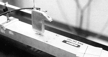
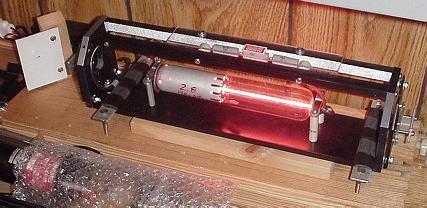
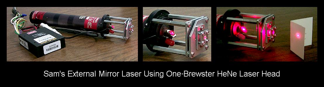
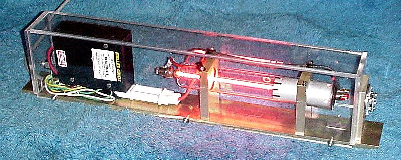
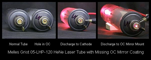