The original laser invented in 1960 was a solid state laser. It used a synthetic ruby rod (chromium doped aluminum oxide) with mirrors on both ends (one semitransparent) pumped with a helical xenon flashlamp surrounding the rod. The lamp was similar to what is used for indoor and high speed photography. The intense flash of blue-white light raised some of the chromium atoms in the matrix (the aluminum oxide is just for structure and is inert as far as the laser process is concerned) to an upper energy state from which they could participate in stimulated emissions (see the chapter: What is a Laser and How Does It Work? for a brief explanation if this isn't familiar to you. The result was an intense pulse of coherent red light at 694.3 nm - the first ever laser light in the world. Gas and semiconductor lasers followed closely behind but only the SS laser can claim to be first.
It was found early on that these lasers could burst balloons and blow holes in razor blades and someone even attempted to coin a new measure of laser energy to be measured in 'Gillettes' based on how many razor blades could be holed at once. :) And, the popular notion that hand-held death ray weapons would soon follow are based on these sorts of demos of solid state lasers, not on whimpy gas lasers (though the carbon dioxide laser is actually a much more likely candidate being the classic heat-ray of science fiction)!
SS lasers are used in all sorts of applications including materials processing (cutting, drilling, welding, marking, heat treating, etc.), semiconductor fabrication (wafer cutting, IC trimming), the graphic arts (high-end printing and copying), medical and surgical, rangefinders and other types of measurement, scientific research, entertainment, and many others where high peak power and/or high continuous power are required. A high energy pulsed YAG laser has even been used in rocket propulsion experiments (well, at least to send an ounce or so aluminum projectile a few feet into the air using just the pressure of photons!). The largest lasers (with the highest peak power) in the World are solid state lasers. Many of the laser projectors for light shows and for other laser displays use solid state rather than gas lasers like argon or krypton ion. And, that green laser pointer is a Diode Pumped Solid State (DPSS) laser.
The exact wavelength of the strongest lasing lines depends on the actual host material but usually doesn't vary that much. In addition to Nd:YAG and Nd:YVO4 at 1,064 nm, examples that lase at slightly shorter wavelengths include Nd:LSB at 1,062 nm, Nd:Glass at 1,060 nm and Nd:YLF at 1,053 nm. However, the lasing wavelengths of some like Nd:NiNbO3 (niodymium doped lithium niobate, 1,084 nm and 1,092 nm) are longer and further away.
Other materials include holmium doped YAG (Ho:YAG) or Ho:YLF. These lase at around 2,060 and 2,100 nm respectively. In the fiberoptic arena, erbium doped glass (Er:Glass) may be used in optical repeaters and amplifiers at around 1,540 nm. Er:YAG lases at 2,840 nm.
Beyond these, there are not that many examples of widely used commercial solid state lasers though many other materials are capable of the population inversion needed for laser action. The workhorse by far is still Nd:YAG with Nd:YVO4 becoming increasingly important for low to medium power (up to a few watts) 1,064 nm and frequency doubled 532 nm (green) diode pumped solid state lasers.
Energy output is measured in joules (Watt-seconds) per pulse. Multiply this by the number of pulses/second to calculate average power output. To determine the peak power in each pulse requires a knowledge of the pulse shape.
Flashlamp pumped SS lasers are used where high peak power is required as most other pumping methods can't even come close. However, the average power and efficiency may be quite low compared to approaches using high power laser diode pumping (see below).
Power output is measured the same way as for other CW lasers.
Depending on the application, the average power output or peak pulse energy or power may be the relevant measurement of performance.
Note that while this output if frequency doubled to 532 nm (green) would appear CW to the human eye, it would NOT be suitable for laser TV or light show scanning since it really isn't continuous.
(From: Anonymous (localnet1@yahoo.com).)
A (laser) diode pumped Nd:YAG may have a 40% efficiency (operating multimode with good thermal control of the diodes), and the pump diodes themselves have about a 45% efficiency, resulting in a net 18% of efficiency from electrical power to the diodes to output beam power. However, at increased pump powers, thermal issues may cause the efficiency to decrease after a certain point. This decrease is power dependent, as well as resonator and pump assembly design dependent.
Unlike HeNe and Ar/Kr ion lasers, there is little standardization of solid state laser components. Laser rods come in all shapes and sizes - some not even rod-shaped :) with or without mirrors (for use with external mirrors and Q-switch optics). They are also relatively expensive as despite their deceptively simple appearance - partly due to the fact that they are a lot fewer of them than laser diodes or HeNe tubes. A price of $300 for a 75 x 5 mm Nd:YAG rod could be a bargain.
The most common type of solid state lasers to have shown up on the surplus market are the laser head assemblies and pulse forming networks from some versions of the M-60 and M-1 tank rangefinders. Yes, if you come across a blown up M-60 or M-1 battle tank in your local junk yard, there may be a laser in there you can salvage! But don't worry, most of the time, you just have to take the laser. :)
In fact, building a solid state laser if you have a Nd:YAG rod with integral mirrors in-hand is very easy - just add a linear flashlamp of with enough energy in close proximity wrapped in degreased aluminum foil! For small rods, a single-use (disposable) pocket camera flash will even work. See the paper: Micro-Laser Range Finder Development: Using the Monolithic Approach.
My first contact with lasers was in the late 1960s when I inherited a student built ruby laser based on a design from Popular Science magazine. This used a ruby rod with integral dielectric mirrors about 1/4" x 3" (this is all from memory) and a linear flashlamp with an energy input of up to 400 W-s. Regrettably, I don't know if it ever worked - the lamp fired fine but I was too chicken to turn the capacitor voltage up to its maximum setting for fear of blowing up the flashlamp! Oh well. :( At least, shortly after that, our high school acquired a *real* 1 mW HeNe laser so I played with that some and used it to view the hologram that was part of an issue of, I believe, Scientific American. Not the same as exploding balloons or drilling holes in razor blades, however. :(
The Laser Equipment Gallery has many detailed views of various solid state lasers from the M-60 Tank rangefinder to a high power arc lamp powered system putting out over 100 W CW.
Some people may only the first one to be a true microchip laser due to the small size of the lasing crystal but I include the other two since their designs are similar. However, in all cases, the only reason the lasing chip is so large in comparison to the active volume is due to manufacturing, handling, mounting, and thermal considerations. Thus, in principle, for the 100 mW green laser, a microrod say 1.2 mm long x 0.2 mm in diameter would be all that is actually required. But until laser chips are fabricated like computer chips and a way is found to get rid of the waste heat, much more material must be used. And, it is the thermal problems that ultimately limit performance - these tiny bits of lasing crystal are potentially capable of much more power output than can be obtained without them being damaged from heating. The smallest mass produced microchip laser crystals I know of are the CASIX DPM0101 hybrid vanadate-KTP module used in some green laser pointers: 1x1x2.5 mm. With cooling on all 4 sides, these may be capable of more than the small number of mW required for a pointer. The larger DPM0102 can generate over 50 mW intermittently at least (but the glue used to cement the two crystals may be damaged by the high intensity green light after awhile).
Melles Griot's low to medium power high quality green DPSS lasers now use composite crystals similar to CASIX's but of their own design optically contacted, not glued, so there is no problem with high intracavity flux. They use optics to shape the pump beam and active TEC cooling so these are much better than laser pointers (and of course cost a lot more as well!). I was told that the cavity is something like 1.5 mm in length (unconfirmed) so this is even shorter than the DPM0101 but it probably has a cross-section more than 1x1 mm. The models currently available produce up to 20 mW but they have gone much higher in the lab. See the section: The Melles Griot 58 GCS Series Green DPSS Laser for more info.
Unlike lamp pumped rod based side-pumped SS lasers which may use much of the volume of the laser rod, end-pumped DPSS lasers typically shape and focus the diode pump beam to a very narrow waist to boost the power density in the lasing crystal and to match the TEM00 mode volume of the cavity. This is an extremely efficient process compared to that of a lamp pumped laser. The typical conversion from diode pump light to IR laser output is over 33%. Compare this to a typical efficiency of 1% for a lamp pumped YAG laser. A DPSS laser may have a better than 10% wall plug efficiency for IR and frequency doubling efficiency (from 1,064 nm IR to 532 nm green) may exceed 50 percent.
Since microchip lasers can use so little actual lasing material and the pump diodes are also very small, they can be very compact, and potentially mass produced and inexpensive. In addition to green laser pointers and low to medium power DPSS IR and green lasers based on YAG or vanadate, all sorts of other SS lasing materials can be used. Of particular interest for communications are erbium (Er) doped materials which lase around 1,530 nm, a wavelength which is optimal for fiber-optic cable.
Microchip lasers also don't necessarily need high pump power. Depending on type, cavity design, and pump beam shape, a few mW of pump beam may be enough to exceed the lasing threshold and they have very high slope efficiency (percent increase in laser output versus increase in pump input) as well.
(From: Doug Little (dmlittle@btinternet.com).)
Like other lasing mediums, the output power from a YAG, ruby, or similar solid state rod will rise according to pump energy - but only up to the point where the active lasing medium is saturated (i.e. all the dopant ions are raised to the upper state). Beyond this point, no amount of extra pump energy will make any difference beyond generating unwanted waste heat. Also, a low-% doped crystal will reach this state more quickly, and will have a longer fluorescence period because the laser 'chain reaction' is inhibited by a reduced population of contributing ions - something like sticking carbon rods in a nuclear reactor to slow it down (well, that's how I like to think of it but feel free to flame, grill, or laser zap me if you think it's a bad analogy :-)
(From: Sam.)
Actually, I think it is an excellent analogy. Just think of all those mouse traps in the upper energy state! :)
(From: Doug.)
The saturation thing is a fairly obvious point, but it would be unfortunate to see enthusiasts building some huge 6-lamp device with a tiny pink ruby rod to find that they get the same output as they could achieve with 2 or 3 lamps! :-)
It would also be nice to have a good clear explanation of doping percent differences and what effect this typically has on laser action. It can make a big difference when you are designing a laser that will work properly even with reasonably well known pump energies.
(From: Sam.)
Yes, the last item would be nice. Are you volunteering? :) However, realistically, where the laser rod is surplus, there probably isn't any easy way to determine the doping percent or control it!
(From: Bob.)
There are all sorts of things that limit the amount of output energy or power from a given size crystal including: damage threshold of the laser medium, energy storage capacity of the laser medium, thermal considerations, and optical considerations (such as self focusing and thermal lensing). You can scale any laser, but there comes a point where you have to make the laser bigger to get more energy. Look at the NOVA laser at Lawrence Livermore National Labs: The light starts out in a small laser rod that could be placed in the palm of your hand, then it gets amplified in a chain of laser amplifiers that take up the area of a football STADIUM!
(From: Ed Xavier Gonzalez (ohlaser@flash.net).)
"Short pulse YAGs can do considerable damage, and can possibly ignite insignificant metals without warning. I have (on only one occasion) accidentally ignited some very fine stainless steel powder. I thought that was impossible until I read the MSDS on some commercially available material. Long pulse YAGs will burn very deeply and can do biological damage if not handled with respect (experience talking). Typically, long pulse YAGs mark alumina ceramic and stainless very well without removing much material. The short pulse YAGs will definitely remove material, but have a tendency to ablate rather than mark."
The document: Safety Guidelines for High Voltage and/or Line Powered Equipment should be thoroughly studied before even thinking about working on any of the power supplies for solid state lasers. ALWAYS assume the capacitors are charged - never assume they are safe to touch even if the laser has been left unplugged for weeks!
More information on the specific electrical dangers are outlined below.
There are several potential hazards in dealing with the innards of electronic flash, solid state laser power supplies, and other xenon strobe equipment.
High voltage with high energy storage is an instantly deadly combination. Treat all of these capacitors - even those in tiny pocket cameras with the same respect as a loaded gun or stick of dynamite. Always confirm that they are fully discharged before even thinking about touching anything. On larger systems especially, install a shorting jumper after discharging just to be sure - these types of capacitors commonly recover a portion of their original charge without additional power input. In the case of an SS laser capacitor bank, it doesn't take a very large portion to be fatal. Better to kill the power supply than yourself if you forget to remove the shorting bar when powering up the unit.
Some links:
Reading and following these recommendations and heeding the warnings is especially important when working with high power solid state laser power supplies or xenon strobes of any kind.
For solid state lasers provided as kits of parts (which is probably the most common for types like Nd:YAG or ruby other than the M-60 rangefinder), be aware that the only type that can likely be made to work easily are those that are flashlamp pumped unless you have access to high power laser diodes of the proper wavelength. The rod must be optically polished and coated (HR, OC, or AR as appropriate) - you won't do that in your basement. See the section: Grinding and Polishing a Ruby Rod.
Using broad band sources like halogen lamps or the Sun for pumping is extremely difficult due to the limited range of wavelengths that matches the lasing medium's absorption spectrum and the huge amount of waste heat. And, any claims about CW operation for some of these are often totally bogus as the physics simply prohibits it.
(From: Chris Chagaris (pyro@grolen.com).)
Commercial laser rods are typically finished with the following specifications: Ends flat to l/10 wavelength, ends parallel to � 4 arc seconds, perpendicularity to the rod axis to � 5 minutes, rod axis parallel to within � 5� to [111] direction. These tolerances cannot readably be achieved by the home experimenter. All commercial laser rods also have anti-reflection coatings applied to their ends which must also be done professionally. If the mirrors aren't included or part of the rod itself, they will have to be purchased separately.
The CW pumping of ruby is not impossible but nearly so, with terrible efficiencies. The pumping of ruby or Ti:sapphire to threshold is literally impossible using tungsten-halogen lamps as has been suggested by some uninformed individuals. Ruby's main absorption bands are located at 404 nm and 554 nm and Ti:sapphire's peaks at about 490 nm. Tungsten-halogen lamps have an emission maximum at 840 nm which is very far from the either of these crystal's absorption bands. Radiation output at the blue and green wavelengths is very poor in these types of lamps, hence another major problem.
Finally, ruby has a very high excitation threshold, being a three-level system, despite its fairly long fluorescence lifetime of 3 ms (at 300K). In early experimental tests, a very small ruby rod (2 mm diameter x 50 mm length) was pumped by special capillary mercury arc lamps (good spectral match) and it took an input of 2.9 kW to produce a CW output of 1.3 watts. Only a small portion of the ruby was excited by the filament arc and laser action only occurred in 6 x 10⁻³ cm3. Using this data, the lamp input power per unit volume of active material to obtain threshold is about 230 kW per cubic centimeter.
While portions are quite technical with many equations, much of it can be read and understood without a fancy college degree. The book has been published in several editions betweem 1976 and 1999. The earlier ones (which may be available at reasonable prices from used technical book sellers) are probably better for pulsed lasers as some material on this topic has been dropped in the latest (5th) edition in favor of more coverage of diode pumped solid state lasers.
Some other relavent publications can be found in the chapter: Laser Information Resources.
There are a number of Web sites with laser information and tutorials.
In particular:
See the section: On-Line Introduction to Lasers for the current status and on-line links to these courses, and additional CORD LEOT modules and other courses relevant to the theory, construction, and power supplies for these and other types of lasers.
Special thanks to Chris Chagaris (pyro@grolen.com and Wes Ellison (erl@sunflower.com) for their contributions to this document and their comments and additions to the chapters on solid state lasers and power supplies.
The basic structure of the SS Laser hasn't changed in any fundamental way since its invention in 1960. A transparent rod (most common shape) doped with a small amount of impurity (the actual lasing medium) is optically pumped by a light source (most commonly one or more linear xenon flashlamps or an array of high power laser diodes) whose spectrum contains significant energy at wavelengths matching one or more of the absorption lines of the lasing medium. One or both mirrors are either an integral part of the laser rod or external. A Q-switch device is often included to compress and boost the energy in the output pulse (pulsed or quasi-pulsed lasers only) with some loss in total energy or average power at the fundamental wavelength. Additional devices such as an intra-cavity frequency harmonic generation crystal (most commonly, doubling - second harmonic generation or SRG) or external Optical Parametric Oscillator (OPO) may be added. Total output energy or average power may actually increase compared to CW operation due to the non-linear behavior of these processes.
Properly selecting the cavity components and driving the pump source properly can make all the difference in terms of output pulse energy, beam quality, and stability.
Matching the PFN to the flashlamp, rod material, and cavity optics is critical in achieving efficient (as these things go) pumping of the laser. For example, just one parameter - the flashlamp pulse duration - can easily determine whether a modest input energy will result in an output beam, whether 10 times this energy will be needed, or whether it the laser will do anything at all. For a given total pulse energy, if the pulse duration is too long, lasing will be erratic or non-existent. Normally, it should be designed to be shorter than the fluorescence lifetime of the lasing medium. As the pulse becomes shorter and shorter, the peak output power and pulse consistency will approach that of a Q-switched laser. However, designing a PFN for a very short pulse is difficult and expensive, and the flashlamp must be derated and its life reduced for very short pulses. Thus, practical direct drive schemes can never compete with Q-switching. The PFN for a typical non-Q-switched Nd:YAG laser will produce a 100 to 200 us pulse which is well matched to the Nd:YAG's 230 us fluorescence lifetime but will result in a series of variable size pulses rather than a single short large one.
See the chapter: SS Laser Power Supplies for more information.
However, most of our attention will be devoted to the common rod shape for lamp pumped solid state lasers and "microchips" for diode pumped solid state lasers.
Other important solid state lasing materials include:
Some additional notes on the comparison of amorphous (glass) and crystalline lasing material:
(From: M. C. D. Roos (roosmcd@dds.nl).)
Straight out of my text-book (1975 and first edition):
"Glass laser hosts are optically isotropic and easy to fabricate, posses excellent optical quality, and are hard enough to accept and retain optical finishes. In most cases glasses may be more heavily and more homogeneously doped than crystals, and in general, glasses posses broader absorption bands and exhibit longer fluorescence decay times. The primary disadvantage of glass are its broad fluorescence line widths (leading to higher thresholds), its significantly lower thermal conductivity (a factor of 10, leading to thermally induced birefringence and distortion when operated at high pulse repetition rates or high average powers), and its susceptibility to solarization (darkening due to color centers which are formed in the glass as a result of the UV radiation from the flashlamps). These disadvantages limit the use of glass laser rod for CW and high-repetition rate lasers."
Nd:YAG has been effectively pumped by various sources including flashlamps (xenon and krypton), krypton CW arc lamps, tungsten-halogen lamps, and high power laser diodes. At current densities of lass than 4,000 A/cm2, both xenon and krypton have a good match with the absorption curve of Nd:YAG laser material. Even some more exotic methods have been used, such as sun-pumped, flashbulb-pumped, and explosively-pumped. The availability of high quality surplus Nd:YAG rods at reasonable prices on the surplus market make this material very attractive to the home-experimenter. Using one of these to make a flashlamp pumped pulsed laser is quite easy.
Nd:YAG, Nd:YVO4, and Nd:YLF are common in diode-pumped lasers. But, the most effective is the newly developed laser crystal Nd:LaSc3(BO3)4 or Nd:LSB. Nd:LSB has has absorption and radiation cross section similar to Nd:YAG but the bands are five time wider. The absorption coefficient of Nd3+ (10%at) in LSB is three times higher than Nd:YAG. LSB can be very heavily doped with Nd3+ (until 50%at), which provides record efficiency in the end-pumped configuration. This is a very high level in comparison with YAG (1.2% before luminescence quenching) or YVO4 3%, and 1.5% YLF. Furthermore, the saturation intensity of Nd:LSB is five times bigger than those of YAG or LSB.
For example, using a microchip 0.5 mm thick and 2 to 3 mm in diameter, is is possible to obtain 0.5 to 50 mW of green output at 531 nm. Q-switch mode in such a microchip is possible with a Cr4+:YAG absorber. On LSB with KTP for SHG grown in Russia, BREMLAS is producing powerful green lasers with cubic inch dimensions. A 10 W green microlaser is under development.
The wavelength for vanadate is more precisely 1,064.3 nm. There is also a weaker line at 1,342 nm.
(Portions from: Juozas Reksnys (rexnys@uj.pfi.lt).)
This most powerful lasing Nd:YAG line is composed from two lines 1,064.17 nm (strong line) and 1,064.4 (week line). At room temperature, the half-width of lasing line is 6.5 cm-1 which exceeds the distance of 2 cm-1 between two lines. Therefore, they are a joint line.
The wavelength of this line depends on temperature. In the practical range of +/-60 °C, it linearly shifts to longer wavelengths during heating by ratio 5x10⁻³ nm/deg. At 27 °C (300 °K), the center of the lasing line is at 1,064.15 nm.
In addition to the common 1,064 nm wavelength, Nd:YAG has over a dozen other weaker lasing transitions between 1,052 nm and 1,444 nm.
(From: Sam.)
However, the vanadate and YAG wavelengths are close enough (0.15 nm) that a lamp or diode pumped YAG crystal can be used as an amplifier for the output of a vanadate laser in a (MOPA - Master Oscillator Power Amplifier) configuration since the gain bandwidth of YAG is about 0.5 nm.
(From: Bob.)
KGW has a NICE broad absorption spectrum, that makes it a lot easier to work with than YAG BUT its thermal properties are poor.
I have a paper titled "Generation of visible light with diode pumped solid state lasers" by Boller/Bartschke/Knappe/Wallenstein from 1993 that was published in "Solid State Lasers: New Developments and Applications" Edited by M.Inguscio and R. Wallenstein, Plenum Press, New York, 1993. This long paper (17 pages) focuses on NYAB. The authors state: "We report the so far highest 531 nm output power of 130 mW generated with 1.55 Watt of diode pumping."
(From: Milan Karakas (mkarakas@vk.tel.hr).)
I have a Nd:KGW rod 5 mm diameter x 50 mm long. This is a neodymium doped potassium-gadolinium tungstate single crystal. Complete data fo this rod may found at: Institute of Inorganic Chemistry Laser and Optoelectronics Crystals (Russia). This crystal has a Nd doping of 3% and operates at 1067.2 nm with 4 to 6% efficiency (Q-switched, 6.3 mm x 75 mm at 50 Hz), 3% efficiency CW, and 60% efficiency when diode pumped laser (quasi CW). The lasing threshold is extremely low - 0.2 - 1 J! I have not found reasonably priced optics for this laser (we may use optic for classic Nd:YAG, because wavelength is close) and pump source with low thermal emission (808 nm laser or LED). The rod was inexpensive - $209 USD including DHL shipping and duty.
(From: Bob.)
NYAB is a self-doubling (combined lasing and non-linear crystal) but it has a much lower doubling efficiency than traditional vanadate/KTP or YAG/KTP. The numbers I have seen are on the order of about 30 mW out for 1 W of diode pumping (efficiency is much higher with Ti:Saph pumping, but it's kind of inconvenient to have a such a laser pump a 100 mW 532 nm system, not to mention expensive. :)
The following is from a 1990 paper so better performance is likely: "Work on diode-pumped self-doubling lasers is still in the early phases of development. The most attractive nonlinear gain medium is Nd:YAB, which is a dilute form of the stoichiometric neodymium compound neodymium aluminum borate (NAB). Diode-pumped Nd:YAB lasers with output powers in the milliwatt range have been demonstrated (reference 10.67)"
There are slight variations in the peak wavelengths for different types of Nd doped glasses. These differences are only very slight and should not be of great concern. The following are some glass types and peak emission wavelengths:
Ruby rods for lasers are made synthetically. Aluminum Oxide (Al2O3) with a very small amount of chromium impurity is melted in an induction furnace. A seed crystal (perhaps a natural ruby or a chip off another synthetic crystal) is stuck into the melt on a rod then slowly withdrawn. A cylindrical rod of "ruby" crystal is formed and is slowly pulled out of the melt. This rod is then cut up and ground with diamond machining equipment to form the precisely shaped laser rod. The ends are polished to extreme levels and then treated with whatever optical coatings are desired, depending on the design of the laser (i.e., mirrors directly on the rod or external).
(From: Mark W. Lund (mlund@moxtek.com).)
There are several ways to do this. The first is the easiest, to pull from the melt. You can melt Al2O3 in molybdenum crucibles and pull a crystal directly from the melt. Even single crystal tubes and other shapes having a fixed cross section can be pulled using a technique called "edge defined growth." Unfortunately, because of the incredible temperatures that sapphire melts at any dopants that you might want to use vaporize, so you can't make red or blue material, only water-white material.
If you want colored sapphire or ruby there are two more methods used. The first, Vernuile (sp?), uses a hydrogen-oxygen flame and drops powdered Al2O3 plus dopant through the flame. The flame melts the powder, which falls on the seed crystal and crystalizes. Because only the surface of the crystal is molten the dopant gets incorporated into the bulk. The crystals are called boules, and look vaguely like a pop bottle, with a small neck, opening up into a cylindrical crystal. The stresses are so enormous in these boules that when you snap the neck off the entire crystal breaks into several pieces along the axis of the boule. Most colored sapphire and ruby sold is made this way, including the watch jewels.
The last method used commonly is flux growth. The Al2O3 is dissolved in a molten salt, usually lead oxide plus cryolite, in a platinum crucible. The crystals come out of solution as the melt is cooled just like sugar in hot water. These are the most desirable of the synthetic stones because they look more like natural stones after cutting, and the process is the most expensive.
(From: Fred Perry.)
Actually, Union Carbide in Washougal Washington makes synthetic Ruby and other colored variants of Al2O3 (sapphire) by the Czochralski method. I bought an nice big CZ 'ruby' gemstone from UC at CLEO a few years ago. You are right that it is hard to get dopants to dissolve in the pot; but this is more a limitation on max concentration and hence achieved depth of color than something that can't be done at all. UC in fact makes (sole source - patented) the 'ruby' laser rods that were discussed in another post this week. They are pink, not red.
(From: Mark.)
Hmm, whom am I going to believe, Fred, whom I have a lot of respect for, or me, whom I have to live with? CZ is usually the method of choice if you can grow a crystal, but I have never seen a paper or patent on CZ growth of colored sapphire. I can't imagine going through all the pain and cost of flux growth or Vernuile if you could pull it from the melt. The method of choice for lasers, by the way, was flux growth when I last looked. On the other hand, if anyone could do it it would be Union Carbide, and it has been a few years since I did search the literature.
I can imagine that some kind of sealed high pressure CZ puller could drive the dopants back into the melt.
Of course the dopant level of a ruby laser is much less than a gemstone. How do they grow titanium doped sapphire? Anyone know?
(From: charlesk@vloc.com.)
As Fred pointed out UC grows ruby by Czochralski as does VLOC (without patent violations, mind you) and we do it quite well as pointed out by the Rogers (Thanks for the recommend). Mark, Czochralski is the preferred method for ruby growth for lasers, has been for a while. Now Ti:Sapphire is a different story, probably due to the higher dopant levels as you surmised. Crystal Systems can probably answer that point.
There is more information on the VLOC Web Site.
"Does Nd:YAG material yield interesting gems when cut? Is it actually considered a "gem"? I think I have a piece of scrap material left over after a bunch of laser rods were cut from it. It's interesting to show to people because it appears transparent to slightly yellowish under most fluorescent illumination, but becomes magenta/pink under full-spectrum illumination."
(From: Chris Cox (ccox@slip.net).)
Yes, and gem faceters like it. Nd:YAG is considered a man-made gem material. It will go almost clear under some more recent rare-earth fluorescent lamps (which confused me when I brought some home. ;-)
There are many types of these crystals, which are referred to as "color change" materials in lapidary/gemstone circles.
(From: Uncle Al (UncleAl0@hate.spam.net).)
Ditto glassblowers' didymium glass lenses and the fabulous gem alexandrite, sunlight versus candle light or incandescent illumination (blue in sunlight, red in cool illumination).
See: "Man-Made Gemstones" by Elwell.
Laser crystals make more than passable gems if they are hard enough to retain facetting and especially if they are optically isotropic. Pale laser ruby doesn't look like much, but if you give it a megarad of Co60 gamma (piggyback on a medical sterilization) you get a superlative tawny orange. (Facet first, because warming to above 100 C gives F-center decay and an eerie deep red glow as it returns to pale pink).
(From: A. E. Siegman" (siegman@stanford.edu).)
I also have a vague memory that maybe there was a diamond solid state laser doped with Cr or Fe or a RE at some point way back, but I'm not sure about that, and you'll have to do the digging in some of the standard handbooks of laser transitions to check if this is correct.
If by a "diamond laser" you mean in general "diamond as the host material, doped with something as the laser atoms", well then diamond is just another host, competing with YAG, sapphire, etc It might have some useful attributes in competition with these others -- thermal conductivity, fracture strength, ability to polish -- but the others are already generally pretty good, and diamond isn't likely to be a miracle material in comparison.
An interesting connection between diamond and laser technology is that some diamonds have small internal flaws that are visible because they contain some uncrystallized carbon or other impurities. If you use laser drilling to drill a tiny tunnel in to the hole and vaporize out the impurity, the remaining tunnel and empty void inside the diamond become much less visible because of the high index of diamond, and the diamond's value as a gemstone can be substantially increased. I believe this practice is in routine commercial use.
I recall that in the '60s I had a visitor who was in the diamond industry and wanted to start up a venture to implement this technique. Getting involved in that kind of imaginative venture wasn't my thing at the time (or ever, I'm afraid), so I didn't jump at the chance -- maybe I should have.
Of course there was also the marine researcher who wanted to develop a CO2 laser gun to brand serial numbers on whales as they surfaced, to make marine surveys more accurate -- and the student who wanted to mount a similar laser on a pickup truck to brand cattle on the fly, which I think later actually got tried somewhere, and may in fact be a good idea. And so on.
(From: Harvey Rutt xh.ruttx@x.ecs.soton.ac.uk).)
And in our lab then the guy who wanted to slice mushrooms which apparently difficult commercially (can't keep the knives sharp enough it was claimed), and substantial money was spent on slicing up foamed toffee brittle into bars with lasers (it sticks to the slitting knives...) but the customers didn't like the caramelised taste!
However, RE: diamond.
Aside from the 'technological' issues such as thermal conductivity, toughness and hardness etc there are some more fundamental issues which don't seem to have been mentioned.
If you go for a dopant system, you need solubility of the dopant. Diamond is a strongly covalent lattice, with a very small covalent radius. This will make it hard to get the typical laser ions in in any reasonable amount in the right valence state. Also the crystal field strength and symmetry at the impurity site has to be 'right' to provide appropriate energy levels (Tanabe Sugano diagrams, if I spelled it right); they will be very different in diamond I suspect, and might need different dopants and level schemes. So you might be looking to unconventional, small atom impurities with a liking for covalent sites, like nitrogen which is well known in diamond; but are there any suitable level schemes?
You also need good (low) non radiative relaxation rates from the upper laser state; but diamond must have very high phonon energies (light atoms, strongly bound) which correlate with high non radiative rates. This will be especially bad for IR transitions (its the photon to phonon energy ratio that matters, if less than 5 or 6, trouble usually.)
If you tried to do a diode laser, I assume diamond is an indirect semiconductor like Ge and Si? (I don't know - does anyone?) and I think injection diode lasers are not possible in an indirect gap material - aside from getting adequate doping densities and profiles, but thats mere technology :-)
A colour centre laser? That might be the best bet, if some diamond colour centre has suitable levels. But it must be said the many conventional alkali halide, etc., colour centre lasers were all a bit pathetic and have been dropped.
(From: Professor Siegmen.)
Harvey's comments, as always, informed, to the point, and well put.
Just in case it might be of interest to the OP, I believe there were at one time some experiments on doped s-s lasers in another gemstone material, emerald, and they also seem to have been dropped.
Also, alexandrite (is that considered a gemstone?), which does offer some special advantages and was commercialized by a company called Light Age, spun out of Allied Chemical, though it's not been a roaring success.
A ceramic is formed by using heat and pressure to merge a nano-fine powder of the desired material at slightly below its melting point. The result is not a single crystal but an aggregate of small crystals. Nonetheless, the ratio of crystal volume to grain boundary volume is so large that the lasing behavior is almost identical to that of a single crystal (i.e., the result with Nd:YAG is a homogeneously broadened gain profile just like the crystalline host).
There are a number of benefits to using a ceramic rather than a crystalline host. Some of the most important include:
While performance is not quite as good as with single crystals, it's getting there. Expect a ceramic solid state laser in your future!
Flashlamps are the method of choice where high peak power is required. None of the alternatives can produce the short, high intensity, burst of light needed to pump a solid state laser for the generation of optical output pulses with peak power measured in Megawatts or more. While the xenon flashlamp is most common, other gas fills may be used to tailor the output spectrum to more closely match the absorption bands of the solid state lasing medium. However, none are really that great and most of the light ends up as waste heat that must be removed - one of the major limitations on maximum pulse rate.
Arc lamps were used in the past where CW operation was required. However, a major difficulty with these was the need to remove kWs or 10s of kW of waste heat from the lamp, rod, and cavity components. Circulating water or oil was needed along with a separate 'chiller' unit for cooling. Arc lamps are rapidly being replaced by arrays of high power laser diodes which are at least 10 times more efficient partially because their output is at the precise absorption wavelength of the solid state lasing medium. They can usually be convection or force air cooled and operate from a regular 115 VAC outlet.
Other types of light sources including the Sun and halogen lamps have been used where the physics permits (Nd:YAG, for example), but their efficiency is very low and the heat dissipation problems are significant. Due to the continuous spectrum produced by these sources, the percentage of light that matches the absorption bands of the solid state lasing medium is quite small. And, for the halogen lamp, at most 10 percent of the electrical input power ends up as visible light to begin with (the rest is IR or heat with a bit of UV).
(From: Leonard Migliore (lm@laserk.com).)
There are lots of CW Nd:YAG lasers. Laser markers are, most commonly, CW-pumped Q-switched Nd:YAG lasers. The rod (or slab) is generally immersed in water, with illumination by arc lamps or diodes going through the water. They get very unhappy with even a momentary loss of cooling.
The laser mode is quite sensitive to the amount of heat being pumped into the rod; they only work properly over a narrow range of lamp currents. I don't think you could get any output out of an air-cooled YAG rod before it cracked.
There are many possible configurations. Which one is used may depend on many factors including the type and shape of the lasing medium (rod, slab, etc.), cooling requirements, and cost:
The cavity reflector is often made of polished metal formed or milled to the desired ellipsoidal or other shape. However, some lasers may use a compacted white powder coating on the outside of the glass or quartz flow tube holding the rod and lamp(s) or between flow tubes. The exact composition isn't critical as long as it has a high reflectivity and is stable. One such material contains barium sulfate (See: Labsphere - WRC-680 White Coating). Another one is magnesium oxide. Similar products are available from Edmund Scientific (actually made by Kodak). It is sprayed on from a can. In general, I wouldn't recommend attempting to remove these sorts of coatings unless they are visibly damaged.
A common model of linear flashlamp is the EG&G FXQ-1300-2 which has a total length of 115.8 mm long, 4 mm outside diameter, and 2 mm inside diameter.
For the FXQ-1300-2, above, the rating is 500 V.
For the FXQ-1300-2, the maximum explosion energy is 140 joules at a 100 us pulse duration and 500 joules at 1 ms.
See EG&G 1300 Series Linear Flashlamp Specifications and Links for detailed info on the other models.
Here are some notes on the K factor and its relationship to flashlamp voltage and current:
(From: Don Klipstein (don@misty.com).)
For more, see the section: Flashlamp and Arc Lamp Manufacturers and References.
This data used to be available on the EG&G, now Perkin-Elmer, Web site but for now at least, much of it is gone. If you want more info, request their CDROM which includes complete product specs as well as the EG&G technical papers that used to be at their Web site. This material is also available at Polytec PI France - Department Electro-Optique. A variety of useful information is available for driving flashlamps (and other topics) at Perkin Elmer Optoelectronics under "White Papers".
Mechanical specifications:
              Bore   Arc     Tube    Overall
  Flashlamp   Size Length  Diameter  Length
    Type      (mm) (in/mm)   (mm)    (in/mm)
-----------------------------------------------
 FXQ-1300-1    2    1/25      4     3.56/90.4
 FXQ-1300-2    2    2/51      4     4.56/115.8
 FXQ-1300-3    2    3/76      4     5.56/141.2

 FXQ-1301-1    3    1/25      5     3.56/90.4
 FXQ-1301-2    3    2/51      5     4.56/115.8
 FXQ-1301-3    3    3/76      5     5.56/141.2

 FXQ-1302-2    4    2/51      6     4.56/115.8
 FXQ-1302-3    4    3/76      6     5.56/141.2
 FXQ-1302-4    4    4/102     6     6.56/166.6
 FXQ-1302-6    4    6/152     6     8.56/217.4
 FXQ-1302-10   4   10/254     6    12.56/319.0

 FXQ-1303-2    5    2/51      7     4.56/115.8
 FXQ-1303-4    5    4/102     7     6.56/166.6
 FXQ-1303-6    5    6/152     7     8.56/217.4

 FXQ-1304-3    6    3/76      8     5.56/141.2
 FXQ-1304-4    6    4/102     8     6.56/166.6
 FXQ-1304-6    6    6/152     8     8.56/217.4

 FXQ-1305-3    7    3/76      9     6.06/153.9
 FXQ-1305-4    7    4/102     9     7.06/179.3
 FXQ-1305-6    7    6/152     9     9.06/230.1
 FXQ-1305-9    7    9/229     9    12.06/306.3
Electrical specifications:
All lamps listed are filled to a xenon pressure of 450 Torr. They are designed for convection or forced air cooling. Water cooling is not recommended. Lamps may operate with either series or parallel triggering and are supplied with a trigger wire. Minimum flashing voltage parameters assume an unloaded trigger pulse.
                                     Maximum      Minimum
               Ko       Minimum      Average      Trigger       Explosion
 Flashlamp  Impedance   Flashing    Power (W)   Voltage (kV)    Energy (J)
   Type    (ohm-A^0.5) Voltage (V) Conv Forced Series Parallel T=100us T=1ms
------------------------------------------------------------------------------
 FXQ-1300-1   16.2        400        25    50     12      15      70     250
 FXQ-1300-2   32.4        500        50   100     12      15     140     500
 FXQ-1300-3   48.3        600        75   150     12      15     210     750

 FXQ-1301-1   10.8        400        35    70     12      15      90     300
 FXQ-1301-2   21.6        500        70   140     12      15     180     600
 FXQ-1301-3   32.4        600       105   210     12      15     270     900

 FXQ-1302-2   16.2        500       100   200     12      15     240     780
 FXQ-1302-3   24.3        600       150   300     12      15     360    1170
 FXQ-1302-4   32.4        700       200   400     12      15     480    1560
 FXQ-1302-6   48.6        900       300   600     15      20     720    2340
 FXQ-1302-10  81.0       1300       500  1000     15      20    1200    3900

 FXQ-1303-2   13.0        500       120   240     15      20     340    1040
 FXQ-1303-4   25.9        700       240   480     15      20     680    2080
 FXQ-1303-6   38.9        900       360   720     15      20    1020    3120

 FXQ-1304-3   16.2        600       225   450     15      20     600    1800
 FXQ-1304-4   21.6        700       300   600     15      20     800    2400
 FXQ-1304-6   32.4        900       450   900     15      20    1200    3600

 FXQ-1305-3   13.9        600       255   510     15      20     660    2160
 FXQ-1305-4   18.5        700       340   680     15      20     880    2880
 FXQ-1305-6   27.8        900       510  1020     20      25    1320    4320
 FXQ-1305-9   41.6       1200       765  1530     20      25    1980    6480
The following are from the EG&G (now Perkin Elmer) High Performance Flash and Arc Lamps available at the Perkin Elmer Optoelectronics Web site under "Datasheets". Search for "flashlamps".
Explosion energy:
The explosion energy is the energy input at which a particular flashlamp is likely to fail after (or during!) a single shot at a given pulse width. As can be seen, longer pulses result in much higher explosion energy values.
u = k * d * l * (t1/3)1/2
Where:
Note mixed units!
So, explosion energy goes up as the square root of the pulse width.
Here are some approximate guidelines for lamp life versus input energy/explosion energy (Eo/u):
 Eo/u     Life Expectancy (Shots)
----------------------------------
 0.1           >106
 0.2           >105
 0.3           104 - 106
 0.4           1,000 - 30,000
 0.5           200 - 3,000
 0.6           50 - 300
 0.7           10 - 75
 0.8           4 - 20
 0.9           2 - 5
 1.0           1 or less
Ko parameter:
The design of the PFN would be trivial if the flashlamp behaved as a simple resistor. Unfortunately, it is a dynamic impedance with a value designated as Ko (units: ohms-amps1/2). The Ko parameter determines the voltage across the lamp as a function of current just like a resistor except that the effective resistance (ER) is a function of current. For example, at 1 A, the ER of the lamp is Ko; at 100 A, it is Ko/10, at 10,000 A, it is Ko/100, and so forth.
V = Ko * |i|1/2
Where:
                l      p
   Ko = 1.28 * --- * (---)1/5
                d      x
Where:
C, L, and V for optimal PFN design:
Normally, it is desired that the circuit be critically damped. This puts the most energy into the flashlamp in the shortest time without undershoot. For a given flashlamp Ko value, there are unique values for C, L, and V given the desired flash energy and pulse width.
          2 * Eo * a4 * T2
    C = (-----------------)1/3
                 Ko4

         T2
    L = ----
         C

           2 * Eo
    Vo = (--------)1/2
             C
Where:
Peak current:
It is important to know the peak current since it affects the spectral output and to assure that it is within the ratings of the lamp.
             Vo
    Ipk = ---------
           Zo + Rt
Where:
There is also general information on xenon flashlamps including guidelines for estimating appropriate voltages and energy levels for glass and quartz flash tubes on Don Klipstein's Flash and Strobe Page. Don's General Xenon Flash and Strobe Design Guidelines Page which also includes some basic design equations.
And, of course, there is tons of xenon strobe information, handy circuits, and complete schematics in Sam's Strobe FAQ (also mirrored at Don's site, above, and other sites Worldwide).
(From: Chris Chagaris (pyro@grolen.com).)
The maximum energy that a flashlamp can withstand is referred to as the 'explosion energy' and it is the energy at which the flashlamp is most likely to fracture. This explosion energy is determined by a number of factors including the type of lamp, size, and current pulse width. If a flashlamp is indeed built for laser pumping it would be of quartz construction but could actually be a number of different models.
For example, a new, EG&G, FXQ-1302-3 (4 mm bore x 76 mm arc length) flashlamp has an explosion energy of 360 joules for a 100 us pulse. As pulse width is increased, explosion energy rises.
In other words, you cannot just buy any old flashlamp driver and expect it to operate your particular flashlamp. I would suggest building your own pulse forming network for your application. It is not overly difficult (although can be very dangerous) if you have some background in electronics. All the formulas to calculate what you'll require are in a booklet available from EG&G or in any good book that deals with solid-state lasers. Capacitors for operating such a small flashlamp are readily available at very reasonable prices.
(From: Don Klipstein (don@misty.com).)
The "EG&G Linear Flashlamp Technical Brief" has a very general rule that has a fair chance of being good for most quartz flashtubes, even someone else's. As for glass? Stay below both half the quartz limit and the tube's regular ratings, and it will probably be OK. See the section: EG&G 1300 Series Linear Flashlamp Specifications and Links.
And EG&G recommends staying below 30 percent of the explosion energy if you want the tube to have a reasonable life expectancy.
For really short pulse width, the limiting factor is ablation - evaporation of the glass or quartz. The vapor decomposes in the arc and you get oxygen among whatever else. The oxygen really increases voltage requirements for flashing. If the electrodes get hot enough, they may react with the oxygen and may remove most of it, but then you may discolor the inner surface of the tube with oxide in addition to any discolorations from silicon or other decomposition products.
I have been through this, and even did some damage to a quartz tube with just a few joules per flash. Heimann DGS0610 (10 mm arc length) does not like voltage much above 300 volts combined with a few joules of energy, nor 1.5 kV at even a fraction of a joule.
When a flashlamp fails, it may do so quietly or with a bang.
Generally, only laser pump flashlamps or similar ones with a lot of flash energy for their size will likely die spectacularly. When lower power flashlamps such as those used in small to medium size photographic strobes crack, they tend to stay in one piece or sometimes break apart surprisingly quietly.
As for failure modes due to abuse:
Even if the ends appear to be identical, check the manufacturers specs to be sure that they are identical - they probably aren't!
(From: Don Klipstein (don@misty.com).)
Some xenon flashtubes do have identical electrodes and can be operated in either polarity. If the flashtube is polarized, wrong-way operation usually shortens the life by sputtering or overheating the anode (being used as a cathode), or by having getter material evaporated from the normal cathode location, drift to what is being used as the cathode and, discoloring much of the tubing along the way - active metal vapors in discharge lamps tend to have some positive ions and will drift to the negative nd.
I have seen some flashtubes have difficulty flashing the wrong way. Usually an extra hundred volts can force an anode to work as a cathode.
Arc lamps may have thermionic emission materials on their cathodes (but not flashlamps). Abusing an anode as a cathode will usually overheat it, often sputter it, and the arc can have an excessive voltage drop (and then conduct less current) which often leads to the arc being less stable, and the arc tube material can overheat around the anode being abused as a cathode. If the arc voltage rises more than the arc current decreases (common), then the whole lamp can overheat - but I think overheating will mostly be around what is being misused as a cathode. Then again, if the lamp discolors from sputtered electrode material then it can absorb light and overheat.
The simplest electrical test is to apply a current limited high voltage to confirm ionization. The required peak voltage will need to be greater than the trigger voltage for the lamp. An easy way to do this is with a neon sign or oil burner ignition transformer on a Variac. Current limiting is built in. An adjustable high voltage power supply with a few hundred K ohms of high voltage ballast resistance can also be used. Since very little current is required, almost any source of HV will do. The start voltage from a helium-neon laser power supply will be sufficient for smaller lamps.
Start at 0 V and turn it up until the lamp fires. For a small (e.g., 2 inch) xenon flashlamp, this will typically be in the 4 to 8 kV range; for a medium size arc lamp, perhaps 10 to 15 kV; large ones may require 30 kV or more. The start voltage will depend on the gas type (xenon or krypton typically), fill pressure, tube inside diameter, and amount of use or abuse.
At these low currents, the operating voltage is probably no where near what it would be at normal current but with this approach, if the lamp fires at all, it is most likely good. The appearance of the discharge at the gas pressure inside the arc lamps is similar to that of a plasma globe - streamers of lightning that move around in response to (internal) thermal gradients and possibly even (external) proximity to conductive materials like fingers. So, if you don't want to use the lamp for a laser, it could be powered from a little HV module and make an interesting display piece. :)
It should be possible to do further testing of arc lamps using an ion laser power supply (but if running for more than a couple seconds, most excellent cooling will be required). This is left for the advanced course.
Information is available for driving flashlamps (and other topics) on their Web site, though it may not be an easily located place! Start with "White Papers" and "Datasheets", search for "flashlamps". However, much of the product and technical info that used to be on the EG&G Web site is no longer present but this material is available on the Perkin Elmer CDROM, which includes complete product specifications and technical papers. The CDROM is accessed using your normal Web browser. Some flashlamp info is also available at Polytec PI France - Department Electro-Optique.
Includes specifications on arc lamps and flashlamps as well as Flashlamp System Design Calculator.
General technical information on flashlamps and arc lamps may be accessed via their Laser Lamps Download Page.
Some very complete technical notes on driving and triggering of flashlamps has been published by ILC Technology (now part of Perkin Elmer). Some of these include:
These were originally published around 1986 so there may be newer versions. As far as I know, they are not currently on-line but should be available in print by contacting ILC.
The most common arc lamps for solid state laser pumping are the xenon and krypton variety. Specifications for a variety of arc lamps used to be available on the EG&G, now Perkin-Elmer, Web site but for now at least, much of it is gone. If you want more info, request their CDROM which includes complete product specs as well as the EG&G technical papers that used to be at their Web site.
Arc lamp power supplies have a lot in common with ion laser power supplies: a relative low voltage (under 50 to several hundred VDC) at high current (many AMPs) and a high voltage trigger required for starting. (However, with their massive cathode - where much of the destructive energy is dissipated - no heated filament is used.) See the chapters starting with: Ar/Kr Ion Laser Power Supplies for general information on systems that are similar to those for arc lamps.
Modern laser diodes are quite efficient and can be designed to produce the precise wavelength needed to match an absorption band of the solid state lasing medium. For Nd:YAG, this is near-IR at 808 nm. These laser diodes are inexpensive (as these things go) at less than $10 a watt for small quantities in chip form. Arrays of diodes mounted side-by-side of 40, 100, or more total WATTs are commercially available. Multiple such laser diode bars may be arranged surrounding a Nd:YAG rod. Laser systems using several hundred watts of laser diode pump power producing 100 W of coherent 1064 nm output or perhaps 40 or 50 W of 532 nm frequency doubled green output are compact, can be plugged into a standard 115 VAC outlet, and require not special cooling.
Power supplies (usually called 'drivers') for high power laser diodes must be designed for absolute current limiting and to compensate for the change in laser diode characteristics with temperature. These types of laser diodes do not have internal monitor photodiodes like their low power cousins so other techniques must be used to regulate output power. Needless to say, preventing damage to these expensive laser diode arrays during power cycling, from power surges, and many other possible dangers, is extremely critical. See the chapters starting with Diode Lasers for more information.
And, if you are wondering... No, LEDs really can't be used since not even a truckload of those super bright Radio Shack LEDs can be focused to achieve the required power density. (Even the brightest produce at most a few mW compared to the minimum of 1/2 W or so used in the smallest DPSS green laser pointer. In addition, being incoherent, their spectral width is much greater than that of laser diodes for a given power, the electromagnetic field intensity is lower.
Lasers (predating laser diodes) have also been used where their output wavelength matched an absorption band of the target lasing medium. However, until the advent of the high power laser diode, such systems were very expensive, had terrible efficiency, and were probably only used for very specialized applications where there were no alternatives.
I have seen a General Photonics laser that put out 5 W, with a 'few' kW of pump power - 2 or 3 or 4 - don't remember exactly how many. :) This was one HELL of a power hungry beast! The reason is that the emission spectrum is not matched to the laser rod. In theory, if you looked at the emission spectrum, you could shift it up or down by controlling the power to the lamp and thus the temperature. But I have no idea where to suggest one find a spectrum for an off the shelf lamp unless you happened to have a spectrophotometer to measure it. :)
My first laser was built with a 3 mm by 60 mm YAG rod, 2 tungsten halogen lamps, an intracavity piece of lithium niobate, and focusing optic. The rod was cooled by a HUGE flow of forced air, and the laser could be run for 5 or 10 seconds at a time before it would overheat. The mirrors were set in homemade mounts using 8-32 screws - NOT what you would call fine adjustment. :) I used a HeNe laser for alignment, then hoped and prayed when it came time to do actual alignment with the thing running, as there was such little time. After about an hour of turning it on, then letting it cool for a minutes, I saw some flashes of green light. Surely no more than microwatts, but then, I was using a very crude, low power YAG in CW mode.... Still one heck of an accomplishment if I do say so myself. :)
(From: sarlock@twcny.rr.com.)
The HR mirror may be dielectric, metal coated, or a corner or half-corner reflector, to name just a few possibilities depending on the lasing wavelength, presence of additional cavity optics (like a Q-switch), and application. The OC mirror will generally be either a dielectric or resonant optic (like the one in the Hughes rangefinder. A resonant optic is basically a multiplate etalon with at least one of its peak reflectances adjusted to coincide with the lasing line). Both mirrors are likely planar so there are no focused regions inside the rod. However, this is not always the case.
Unlike low gain gas lasers, aluminized (metal coated) mirrors may have enough reflectance (greater than 95 percent) to easily reach threshold in a solid state laser. However, in addition to the less than optimal reflectance for the HR, that missing 5 percent is due to absorption, not transmission. Thus, a significant percentage of the pulse energy inside the resonator will be deposited in the mirror coating as heat. So, the damage threshold for these metal coated mirrors is much lower than for dielectric mirrors (with the highest damage threshold likely to be for resonant type optics). In other words, at some modest peak pulse power, you may end up with a nice clear spot (or worse) where your metallic mirror coating used to be. :(
Where the laser operates at an IR (invisible) wavelength, it generally isn't possible (or at least not easy) to determine the characteristics of dielectric mirrors without test instruments. In fact, it may not even be possible to differentiate between the HR and OC by visual inspection! They may both appear very similar and virtually transparent to visible wavelengths. If you have an unmarked laser head, assume that the beam could emerge from either end unless one is obviously covered! And, a resonant OC will probably appear virtually transparent regardless of the wavelength of the laser.
On two YAG lasers I've seem up close and personal, the little SSY1 and an old large quasi-CW Quantronix Model 114F-O/QS (see the descriptions later in this chapter), the OC had a slight green tint in reflection. The HR of SSY1 was pale blue in reflection and the HR of the Quantronix was pale yellow in reflection. The color of transmitted light in all cases was as expected, a very very pale complement of the reflected color (almost neutral clear). Given that the appearance of the HRs of the two lasers were almost complements of each-another for the same wavelength (1064 nm) suggests that it isn't really possible to determine anything about anything by just viewing the mirror colors of lasers producing invisible outputs. :)
Due to the typically high gain of the lasing medium, and its relatively large diameter, mirror alignment may not be nearly as critical as with narrow-bore low gain gas lasers despite the mirrors very likely being planar. Thus, on a short resonator, it is quite possible for there to be absolutely no adjustments for mirror alignment - just a machined mating surface on the rod-side of the mirror mount.
However, some lasers use a pair of "Risley" prisms between the rod and HR mirror for fine alignment rather than adjustable mirror mounts. A Risley prism is a thin very slightly wedge AR coated glass plate. With two of these that can be rotated and then locked in place, fine alignment of the cavity is possible. Relatively large changes in orientation produce only small changes in alignment which results in greater precision and stability than with adjustable mirror mounts.
Note that SS lasers are often used as amplifiers rather than oscillators - the light makes a single pass through the lasing medium and is boosted in intensity. In that case, there are no mirrors at all!
CAUTION: If the resonator Q is too high due to high reflectivity of both the HR and OC, the peak power could be great enough to damage the rod, optics, and your disposition. :)
(From: Bob.)
Has anyone seen a Nd:YAG crystal lase off of 2 un-AR coated faces before? This hapened to me last night when I was fooling around with some optics, well OK, I did have the help of a 250 W, 808 nm laser diode array. That might have had something to do with it. :)
I have seen it in flash lamp pumed systems. That's why so often you see a pulsed amplifier rod with the ends cut with a wedge, so that you don't have two parallel faces that are normal to the rod axis. But I have never seen it in a CW pumped scinerio, especially as one that is so 'photnically sloppy' All I was doing was holding the rod in front (by hand) to see if the spontanious emmision would be too bright to look at with my infra red viewer. Good thing I didn't look down the axis with my finderscope first, istead of looking at the barrel, the convertor tube in a find-r-scope isn't cheap to replace.
(From: Paul Pax (phpax@azstarnet.com).)
I've seen flashlamp pumped Nd:Glass rods lase from the two AR coated faces before, the face were even at an angle to the rod axis. Got a fair amount of power out, too. I guess if you've got enough pump power, it doesn't take much feedback.
With a normal pulsed laser, the pumping source raises the active atoms of the lasing medium to an upper energy state. Almost immediately (even during the pumping) some will decay, emitting a photon in the processes. This is called spontaneous emission.
If enough of the atoms are in the upper energy state (population inversion) and one of these photons happens to be emitted in the direction so that it will reflect back and forth between the mirrors of the resonator cavity, laser action will commence as it triggers other similar energy transitions and additional photons to be emitted (stimulated emission). However, the resulting laser pulse will be somewhat broad and of random shape from pulse to pulse.
The idea of a Q-switched laser is that the resonator is prevented from being effective until after the pumping pulse and most of the atoms are in the upper energy state (the population inversion in as complete as possible). Its so-called Q is spoiled by in effect disabling one of the mirrors. This can be accomplished mechanically by simply rotating the mirror or an optical element like a prism between the mirror and the lasing medium, or electro-optically using something like a Pockel's cell (a high speed electrically controlled optical shutter) in a similar location. With the cavity not able to resonate (mirror blocked or mirror at the wrong angle), there can be no buildup of stimulated radiation. There will still be the spontaneous emission but this is a small drain on the upper energy state.
At a point in time just after the pumping is complete, the Q is restored so that the resonator is once more intact - the mirror has rotated to be perpendicular to the optical axis, for example. At this instant, with a nearly total population inversion, laser action commences resulting in a short, intense, consistent laser pulse each time and the pump energy is used more efficiently. Peak optical output power can be much greater than it would be without the Q-Switch. Because of the short pulse duration - measured in nanoseconds or picoseconds (or even less), peak power of megawatts or gigawatts may be produced by even modest size lasers - with truly astounding peak power available from large lasers like those found at Lawrence Livermore National Laboratory.
Q-switching can be applied to a single-shot pulsed laser like one pumped with a flashlamp as well as to a continuously pumped laser like one pumped by an arc lamp or laser diodes. For the latter cases which would run CW without the Q-switch, the result will be a quasi-CW output typically at rates up to several kHz. In fact, many green laser pointers (which are diode pumped frequency doubled Nd:YVO4 lasers) utilize a passive Q-switch to boost efficiency in the non-linear doubling process and the output is actually a series of pulses at several kHz. However, the highest peak power is still achieved using flashlamp pumping. As noted above, to Q-switch a laser, the lasing medium needs to be pumped with enough energy before the Q-switch is turned on to supply the laser pulse. For the very common YAG laser, this must happen in a couple hundred microseconds or less (the upper state or fluorescence lifetime of YAG, about 230 us). This would require an arc lamp or diode array to deliver enough energy into the rod in 200 us to result in the desired output energy in the Q-switched lasing pulse. For example, for a very modest 100 mJ output, about 10 J would be needed assuming 1 percent efficiency (as with an arc lamp) or about 1 J assuming 10 percent efficiency (as with laser diodes). This would require a 50,000 W arc lamp or 5,000 W diode array, with all the associated power and cooling issues. Neither of these is very practical while a 10 J flashlamp is barely larger than the electronic flash unit in a disposable camera! So, high Q-switched pulse energies may be possible in principle but whether such systems make sense in terms of cost/performance is another matter. An alternative which is marginally more practical is to use an optical (e.g., YAG) amplifier to boost the output of a lower power Q-switched laser but this would still be a complex expensive system.
With a motor driven Q-switch, a sensor is used to trigger the flash lamp (pump source) just before the mirror or other optical element rotates into position. For the Kerr cell type, a delay circuit is used to open the shutter a precise time after the flash lamp is triggered.
Q-Switched lasers are very often solid state optically pumped types (e.g., Nd:YAG, ruby, etc.) but this technique can be applied to many other (but not all) lasers as well.
A somewhat related process, called cavity dumping, is sort of the opposite of Q-switching: The intra-cavity power is allowed to build to a maximum at which point an electro-optic device is pulsed to cause what is in the cavity to go elsewhere. Thus, a pulse roughly 2*L/c (L is the length of the cavity and c is the speed of light) long is dumped from the cavity.
WARNING: With their extremely high peak power, these are nearly always Class IV lasers! Take extreme care if you are using or attempting the repair of one of these.
CAUTION: For some lasers which run near their power limits, if the cavity is not perfectly aligned, it may be possible to damage the optical components by attempting to run near full power in Q-Switched mode. Perform testing and alignment while free running - not Q-Switched (rotating mirror set up to be perpendicular or shutter open). Use a CCD or other profiling technique to adjust for a perfectly symmetric beam before enabling the Q-Switched mode.
Mechanical Q-switches aren't found that often if at all in modern equipment. In addition to the difficulties in timing, having any high speed, wear prone, low reliability moving parts in a high tech laser is just bad form. :) The only common pulsed laser I know of with a mechanical Q-switch is the popular M-60 Tank rangefinder (which isn't exactly modern).
Alternatives to motors are electromagnetically or piezo-transducer wobbled or vibrated optical elements.
The following comments relate to mechanical Q-switching of a Nd:YAG laser. Since the fluorescence lifetime of YAG is less than 1/10th that of ruby, the difficulty of implementing a mechanical Q-switch are greatly increased.
(From: Bob.)
It may not be as easy to use a rotating Q-switch with YAG, but it certainly can be done. I have seen both a flashlamp pumped system by Litton that was used by the military (presumably part of a REALLY non-eyesafe rangefinder) and a medical laser that was arc lamp pumped from a European company. For the modern laser amateur, perhaps a mirror mount with a piezo transducer under one axis would work better than a rotating prism. But that would require one to be electronic saavy to build a driver.
(From: LaserguruChris (laserguruchris@aol.com).)
Believe it or not the chopping does work somewhat for YAG Q-switching although crude and inefficient. I managed to do this with a CVI YAG max model 95 laser in an attempt to get green out of it. The green power increased from a pathetic 70 uW to about 3 mW average power (still poor since it gave about a couple watts CW at 1,064 nm but better then nothing. :-) With the doubler taken out you could focus the beam enough to make little sparks where it hit. The wheel 1 mm holes cut in the edge separated by 2 mm and was spinning at 55,000 rpm. It is probably extremely difficult to get true Q-switching this way, what you will most likely get is a Q-switch pulse with a CW level "tail".
A variety of electro-optic techniques may be used including the Kerr cell (high voltage driven) which affects the polarization and the Acousto-Optic type (RF driven) which deflects part of the beam out of the cavity thus reducing gain.
(From: Christoph Bollig (laserpower@gmx.net).)
There are three main differences from the optical side between Electro-Optic (EO) Q-switches (e.g., Pockels Cell) and Acousto-Optic (AO) Q-switches:
An additional advantage of AOMs is that they require only low voltages.
From the above, you can easily see why EO was used for low-rep-rate flashlamp-pumped systems with 10s of Hz rep rate but with a very high gain so that fast switching and good loss is important. On continuously lamp-pumped system with high-rep-rate (multi-kHz) and on diode-pumped systems, the AOM is normally the better choice.
Solid state lasers may use frequency multiplication to generate the second harmonic (double or SHG), third harmonic (triple or THG), forth harmonic (quadruple or FHG), and even higher harmonics, though conversion efficiency generally goes down with increasing multiplication factor. The basic doubled solid state laser uses a three step process to obtain green 532 nm light from electrical power:
However, just pointing an CW IR laser at a KTP crystal is not an efficient way of getting this to work. The laser and doubler crystals are usually both inside the cavity (this is called intracavity doubling). The mirrors are designed to have high reflectivity in the IR and to be transparent at 532 nm. So, 1064 nm IR photons bounce back and forth until they are finally convinced to double their frequency and become 532 nm green photons. They then find it easy to escape from the prison. :-) See the sections starting with: Diode Pumped Solid State Lasers for more information on this specific technology.
High energy pulsed lasers can be frequency multiplied directly (outside the cavity) and it is possible to buy an external unit to place in the beam to do this. Aiming the SSY1 pulsed Q-switched Nd:YAG laser's output at a KTP crystal will result in relatively efficient doubling because it it's peak power is very high. However, this isn't practical for low power CW lasers.
And as to your next question, almost any laser can be doubled (or more) but it comes down to a matter of efficiency and cost. For example, with a HeNe laser, it's possible to easily get a few watts of intracavity power inside a long HeNe laser if both mirrors are high reflectors. Even a modestly long one-Brewster laser tube with super polished mirrors can result in 10s of watts. The record may be on the order of 100 W for a reasonable size HeNe laser. In principle, you can put a non-linear crystal in there with a couple of lenses or a lens with one of the mirrors having appropriate curvature to produce a small beam waist inside the crystal. Argon and krypton ion lasers can have even higher intracavity power. All of these as well as diode lasers have been doubled. Whether it's useful and economical is another matter.
Monolithic laser systems, typically small DPSS doubled Nd:YAG or Nd:YV04 systems can be made in one or two ways: They can be assembled or they can be 'grown' in a single boule and sliced up to form microcavity lasers. One must keep in mind that the cavity is very small in these lasers - on the order of a couple of millimeters. Thus, they are very insensitive to misalignment of both the optics and the SHG crystal. A small cheap DPSS (not even a monolithic DPSS, but one with discrete components) may have the optics glued to an assembly or otherwise simply held in place. Gone are the fine adjustments of the traditional laser cavity. All monolithic DPSS systems are low output power, so cooling is not a huge concern. If the system is cooled, however, obviously all the optical elements are at the same temperature. This is completely contrary to the norm found in higher power DPSS systems, where the KTP (or other SHG) is normally at an elevated temperature and the lasing crystal is simply at a stabilized room temperature.
The required type and size of a the non-linear crystal depends on your application.
If you want to do frequency doubling (SHG - Second Harmonic Generation) of a CW or quasi-CW beam them a KTP crystal with a 3 x 3 mm aperture will suffice up to about 70 or 80 W of extracted green output power. If you are looking for higher powers use a 5 x 5 mm crystal and a respectively bigger beam waist. This will give you enough room for outputs of several hundreds of watts, and is the crystal size used in the current record holding laser for most green output power.
If you are thinking of using a SHG crystal for a pulsed laser, KDP would actually be your best bet. As a general rule of thumb with a electro-optically Q-switched laser, you want the spot size on your SHG no smaller than your output beam diameter. As it is extremely expensive to get a large KTP crystal, KDP is often used, and with high power pulsed lasers, the lower nonlinear coefficient is not noticed.
The damage threshold for a normal KTP crystal is 100 to 500 megawatts per square centimeter. The efficiency increases as the power density increases, so the power output at the second harmonic increases exponentially as the power density increases. However, although it is true that the damage threshold is very high in terms of power, it is much lower in terms of energy. Damage can occur at tens of joules per square cm. That's one reason why large doubled YAGs like the Laserscope systems can't be gated with the Q-switch driver. At high repetition rates, the first pulse supression goes isn't effective in those lasers, so the energy goes up in the first pulse eating the optics, normally starting with the KTP.
LBO has a much lower nonlinear coefficient for 1064 nm SHG than KTP. However, it also have a much higher damage threshold. LBO is normally only used in systems that either (1) use very high powers (i.e., 100 W class lasers) or (2) need one of the optical properties of the crystal, such as the small angular acceptance angle. Since LBO has a lower nonlinear coefficient, it requires the use of a much longer crystal.
(From: Christoph Bollig (laserpower@gmx.net).)
In selecting between KTP and LBO for a CW laser, I would say there is one simple reason: Gray tracking.
Have a look at Raicol Crystals and then click on "High Gray Track Resistance (HGTR) KTP for CW and high average power SHG". On the right of that page, there is an image to click on. That give a graph for flux-grown KTP, hydrothermal KTP, and for the Raicol HGTR KTP. I phoned them recently and I think they said that their HGTR KTP is the best you can get. (Does this statement surprise you? --- Sam.) And still, it can handle only up to 10 kW/cm2 of green power density, and that reliably only if you keep it warm.
For a laser like the Coherent Verdi, the output is between 5 and 10 W CW. To keep that below 10 kW/cm2, the beam area has to be at least 1/1000 cm2 or 0.1 mm2. That is roughly a beam diameter of 1/3 mm, not very small for a laser where you want to focus tighter to get good conversion. And that's operating at the limit. I would guess that Coherent would prefer to have some margin there. LBO doesn't have such a problem - you can focus as tight as you wish. The coatings are going to be a problem, if you go too tight, but not damage to the crystal (at least not anywhere near this value).
The problem with LBO is that if you use it at room temperature, you need to use "critical phase matching". (See the section: Phase Matching for Harmonic Generation.) When critically phase matched, LBO has a large walk-off and small acceptance angle, both not what you want when you need to focus tightly for CW conversion. But you can use LBO also in "non-critical phase matching". Then, you have to temperature tune it to ~150 °C and stabilise it there to better then 1 °C. The advantage of non-critical phase matching is no walk-off and a large acceptance angle, so that you can now really focus tightly.
The other disadvantage of LBO is that its non-linearity is much smaller than that of KTP. You need much larger pieces to get a comparable conversion efficiency, and it is significantly more expensive as well. In addition, there is a Chinese company holding US and other patents for it, so it cannot be purchased easily from others if you are in the USA or want to produce a commercial laser, which you intend to sell in the US market in any significant numbers.
We have just ordered two LBO crystals for non-critical phase matching, which we will use to intracavity-double our 23 W Nd:YLF laser. We will see how much we can get with them. I am still thinking to buy one of the Raicol KTPs as well, just to see how far we can get with them. I haven't decided on that yet.
(From: Skywise (skywise@cwixmail.com).)
My copy of Casix's "Crystals and Materials Laser Accessories" lists beta Barium Borate as having been used to generate second, third, fourth, and fifth harmonics of Nd lasers. But KTP is more efficient than BBO for this purpose.
My thoughts so far are as follows: Assume that the input to the non-linear crystal is a sinusoid with a frequency of several 1014 Hz (for visible light). Then assume that the transmittance of the crystal as a function of the instantaneous value of the input signal (i.e., the value of the input signal, which varies between +peak_amplitude and peak_amplitude) is not a straight line, as normal, but rather, a curve, perhaps resembling a log curve, or, curving with the opposite sign, an exponential curve. Then, the signal emerging from the crystal would be distorted, and no longer a pure sinusoid. Then, taking the Fourier transform of the output signal, it would no longer approximate a delta function at the frequency of the input signal, but would contain other components, including harmonics of the input signal.
Is this anywhere near the mark, or is it a different process entirely?
(From: Doug McDonald (mcdonald@scs.uiuc.edu).)
This is correct.
(From: Martin.)
If my guess is anything like correct, it would seem valid to predict that the doubling should not be particularly frequency-specific, so one should be able to use the crystal to double (or triple, etc.) any visible/IR/UV wavelength more or less equally. Yet, I have not heard of this being done. I have not heard of doubling the output of an 808nm pump diode directly (without YAG, etc.) to get UV. This suggests to me that there is strong wavelength-dependence. If so, why?
(From: Doug.)
Now the tricky part. You are thinking like radio frequencies. At readio frequencies, the non-linear element (e.g. diode) is small compared to a wavelength. At optical frequencies it is not. Consider a yagi antenna that has each element nonlinear. It won't work for the second harmonic at all, and will have a vastly different spatial pattern for the third harmonic.
The point is that the non-linear signals from different parts of the crystal have to add up in phase, and this is tricky to arrange because the speed of light is different for different frequencies. You CAN use most doubler crystals for different wavelengths, you just have to tilt them. KTP can't be due to a quirk, and this quirk is why it is so efficient.
(From: Martin.)
Also, why do these doubling crystals need such high input power to "get going"? Is it simply that the non-linearity becomes more noticeable as the amplitude of the input signal increases, and the transmittance curve deviates further from linearity?
(From: Doug.)
Yes.
(From: Martin.)
Is there a well-defined threshold amplitude (or input power) at which things suddenly start happening, or does the amplitude of Nth harmonic light increase gradually with increasing input power?
(From: Doug.)
Thre is no threshold - the output of a doubler crystal is quite "quadratic" up to saturation.
(From: Martin.)
Finally, are tripling/quadrupling crystals made specially as such, or are the same crystals used as for doubling, with the required harmonic selected by intra or post-resonator filtering?
(From: Doug.)
They have to be cut at different angles to get the phase right
(From: Bob.)
First of all, within reason a frequency doubler can be found for any wavelength in question. it's really only a matter of optical transparency at the wavelengths in question, as well as the nonlinear coefficient. There has been some direct doubling of diode laser light. Spectra Diode Labs doubled roughly 900 nm light to get 450 nm. But in order to do this they needed to take the output of a beam conditioned laser diode to a tapered laser amplifier to get a high quality beam that could be manages optically and focused int he SHG crystal. The only reason why you don't see this happen a lot is because the light coming from a laser diode is a PAIN to deal with, and for efficient SHG you need a very good quality beam (at least compared to most laser diodes). The nonlinear efficiency of ANY material increases with power squared - that is the reason why efficient SHG requires a lot of power. People who have been hit in the eye with a high power pulsed YAG laser have reported seeing a flash of green light (normally the last thing they have seen with that eye). This is because the vitreous humor acts as a nonlinear element at very high powers. All materials have a nonlinear coefficient, it's just like an index of refraction, but in this case it is power, as well as wavelength dependent. An ultra high power laser can cause air to act as a nonlinear medium. There is no magic power threshold that SHG processes start at. MOST harmonic crystals are cut for phase matching of a particular process, such as doubling, at a particular wavelength. It is possible to use a 'generic' crystal for any nonlinear process, but efficiency suffers dramatically. A 3rd harmonic crystal is cut for mixing of fundamental and the second harmonic from a doubling crystal. a 4th harmonic crystal is cut for phase matching the SHG process of the 2nd harmonic of a laser, and so on.
(From: Jo.)
KTP is not suitable for doubling to the blue spectrum (it can't be phase matched below about 500 nm). Normally, KNBO3 is used to double the 946 nm line of a Nd:YAG or the 914 nm line of Nd:YVO4. But the efficiency of these lines is poor (10% in comparison with the 1,064 nm emission). Some companies make blue lasers by direct doubling a 980 nm diode. But this is not easy, because you need a very good beam quality which requires a single mode diode - not available at high power. The other problem is that you have to use extra-cavity doubling (since you can't get inside normal diodes!). With cheap multimode diodes, there is no way to do the needed beam shaping. You can build a nice green laser using 980 nm diodes and Yb:KGW (1,025 to 1,045 nm; greater than 50% efficiency) and doubling with KTP. KGW has its major absorption wavelength at 980 nm - the problem is that it is not cheap (starts from $1,000/crystal). I am currently constructing a blue laser (457 nm from Nd:YVO4 or 473 nm from Nd:YAG) and I think there will be some news around the blue lasers next year. Many companies are developing new materials for powerful blue lasers.
(From: Johannes Swartling (johannes.swartling@home.se).)
Consider a loudspeaker's membrane. If you drive the speaker at low volume with a sine wave a a certain frequency you will get a sound at that frequency. If you increase the volume (power), at some point the membrane can't keep up with the harmonic oscillation. You get a distorted sound, which has many different frequencies, especially harmonic overtones that are multiples of the basic frequency.
In a classical interpretation this is what happens in the doubling crystal. The electrons in the material oscillate in the electric field of the light wave. If you increase the light intensity the electrons start to oscillate violently and at some point they no longer follow the nice harmonic trajectories anymore. That's when other frequencies start to be generated, because oscillating electrons emit light waves at the frequencies at which they oscillate.
The next problem is that if the electrons of the individual atoms generate frequencies in a random way, not related to each other, all these effects will cancel out and you don't get anything useful out. Enter phase-matching. Phase-matching is a way to make sure that all atoms in the crystal work together to generate the correct frequency. This is done by aligning the crystal in a certain angle both in respect to the input laser beam and the doubled output beam.
The most important point in frequency doubling is that you need a high laser power (or rather power density) to make the electrons oscillate in a non-harmonic way. That's why it's difficult to get non-linear effects with low power lasers such as HeNe and low-power diodes. Another problem is that the input beam and the frequency-doubled beam are usually not parallel, so you get a walk-off effect. That means a limited interaction length and that limits how much of the power you can convert. In theory you can get 100% conversion if the conditions are the right.
Generating very short wavelengths is a problem because many materials absorb at short wavelengths, so even if you can generate doubled light is doesn't come out of the crystal.
We deal mainly with second harmonic generation which is a special case of two beams interacting in a non-linear material to produce the sum of their frequencies. In this case, they are actually two components of the same beam (with a single frequency) so the result is also half their wavelength. However, the same basic explanation also applies to any non-linear optical process including optical mixing of two beams (for example, one at the fundamental and the other at the second harmonic to produce the 3rd harmonic), OPOs (Optical Parametric Oscillators) and OPAs (Optical Parametric Amplifiers) to generate a pair of new wavelengths from a single input, and so forth.
Non-linear optical processes can be either elastic (optical energy conserving) such as harmonic generation or inelastic (which deposits some energy in the material) such as Raman or Brillouin scattering. We only deal with the elastic case here.
The following is based on material from "Solid State Laser Engineering" by Walter Koechner (5th edition) and has been greatly simplified. See that book for all the gory details.
Non-linear optical processes are based on the response of the dielectric material at the atomic level to the electric fields of an intense light beam. The propagation of a wave through a material produces changes in the spatial and temporal distribution of electrical charges as the electrons and atoms respond to the electromagnetic field, mostly a displacement of the valence (outer) electrons from their normal orbits. This perturbation produces electric dipoles whose macroscopic manifestation is polarization. For small field strengths, the polarization is proportional to the electric field. In the non-linear case, reradiation comes from dipoles that do not faithfully reproduce the electric fields that generates them. The (electrical) polarization wave resulting from this non-linear behavior includes both the original frequency or frequencies as well as the sum and difference frequencies (as with an electronic mixer or other non-linear device).
Whether a given material reacts in a linear or non-linear way depends on its basic composition and structure, the intensity and orientation of the incident wave(s), and their intensity. For each material, there is a parameter (which is a function of orientation) known as the "non-linear coefficient" which determines how sensitive it is for these processes. (However, just having a high non-linear coefficient doesn't necessarily make a given material suitable for anything if its damage threshold or some other property isn't favorable.)
The non-linear effect makes the conversion efficiency proportional to the square of the input power until the material saturates. (Unlike a lasing process, there is no threshold, just very low effeciency at low power levels.) Thus, high peak power is needed to achieve the best performance. This explains why pulsed lasers can be easily frequency doubled using external non-linear crystals but intracavity frequency doubling is much more effective for CW lasers.
Second harmonic generation should be viewed as a two step process:
The typical dispersion values in the visible and near-IR of most crystals limits the coherence length to about 10 um. Thus, the maximum output power will be very small. (If one could stack 10 um thick sections of such a crystal in alternating fashion, it is possible to get around this limitation but such a structure would be prohibitively expensive if it could be fabricated at all. However, this is the concept of "Periodically Poled" non-linear crystals - a topic for a future discussion).
One way around the limited coherence length is to take advantage of the natural birefringence of some materials. Birefringence results in slightly different index of refraction values depending on the direction of polarization of the wave in the crystal. If it was possible to arrange the orientation of the crystal such that the incident (fundamental) and output (harmonic) beams propagated in just the proper directions such that n1 would be exactly equal to n2, the coherence length, and thus the power output, could be greatly increased. It turns out that materials like KDP, KTP, LBO, BBO, and LiNbO3 have suitable dispersion characteristics for phase matching to be accomplished and high enough non-linear coefficient, damage thresholds, and other properties to make them useful for harmonic generation as well as other non-linear optical processes like optical mixing, OPOs, OPAs, etc.
The math is quite hairy and involved :) but from a practical perspective, unless you are manufacturing the crystals, there is no need to worry about the precise angles as the supplier takes care of cutting them so that the orientation in your optical cavity will be something reasonable - usually close to the crystal axis being parallel to the resonator axis, and at either a 90 degree or 45 degree orientation around its axis.
The "Type" of phase matching relateds to the polarization directions of the input and output beams:
The acceptance angle refers to the range of angles over which you can get good phase matching. In the non-pump depleted regime the output power varies with sinc(delta-k * L)2, where delta-k = 2k(fundamental) - k(SHG) is the phase mismatch term. For small deviations dtheta from the proper phase matching angle one can usually approximate delta-k = const. * dtheta. This implies that the acceptance angle, i.e. the range of angles over which the argument of the sinc**2 function is less than unity, will vary with 1/L. In other words, acceptance angle * L is constant - hence the functional form you saw in your text.
To determine how tightly you should focus your beam you need to determine the intensity and interaction length you need to get the desired conversion efficiency. Then focus tightly enough so that your intensity is at the desired level, but not so much so that your Raleigh range is less than the desired interaction length. If you can't do this then you need better beam quality, or more powerful laser or a material with a higher nonlinear coefficient.
The NIF, NOVA, and all the lasers previous to them in the Inertial Confinement Fusion (ICF) programs around the world use external frequency conversion. That's the only way multiply the wavelength of the light from a Master Oscillator - Power Amplifier (MOPA) type laser (you can't multiply the wavelength and than pass the light through the amplifiers because there is no amplifying medium that works at the shorter wavelengths). But here again, the flux is orders of magnitude greater even extra cavity than one deals with for CW sources, especially compared to DPSS lasers. The ICF lasers are run so 'hard' that the optical flux is near the damage threshold, in some cases upwards of 100s of megawatts per square centimeter. As all nonlinear processes have efficiencies based closely on power squared, obviously a 100 MW beam will be doubled much more effectively than a 5 watt beam inside a DPSS laser 5 mm in diameter. That is why solid state lasers get doubled intra-cavity - it greatly increases the power flux at the crystal. In fact, a lot of intra-cavity doubling schemes rely on focusing the beam down at the crystal to make the flux even higher. This is something that would be difficult with diodes due to their poor focusability resulting from their large divergence.
The re-engineering of a medical system is something that is a daunting task typically only for those somewhat versed in NLO systems However with perseverance and much time invested YOU should succeed in the quest and more importantly increase your understanding and knowledge of the NLO systems and their unique quirks......
Any arclamp (CW pumped) YAG system is a viable option for a L-fold or Z-fold NLO system , medical systems are great base line systems for many reasons - they are plentiful, cost effective, and well engineered.
The subsystems needed to typically convert on of these units are as follows:
The wavelengths/frequencies of the three beams must satisfy:
                      1                 1                  1
                -------------- = ---------------- + ---------------
                 Lambda(Pump)     Lambda(Signal)     Lambda(Idler)
or equivalently:
Frequency(Pump) = Frequency(Signal) + Frequency(Idler)
Energy is conserved since this also says that the sum of the energies of the
Signal and Idler photons must equal that of the Pump photon. (The energy of a
photon is proportional to its frequency.)
Unlike lasers using frequency multiplication to obtain shorter wavelengths where the frequencies of the pump and output are related by small integers (SHG=2, THG=3, FHG=4, etc. - see the section: Frequency Multiplication of DPSS Lasers), with OPOs there is NO explicit requirement that the wavelengths of either of the resulting beams be related directly to the wavelength of the pump beam as long as they satisfy the equations, above. Thus, it is possible to implement a laser capable of being continuously tuned over a wide range of wavelengths - as much as several um - by adjustments only of the OPO (not the pump laser).
Also note that while we use the term 'pump' to describe the input source, an OPO is NOT a laser in itself - there is no stimulated emission taking place, just conversion of wavelengths through non-linear optical processes.
In current OPO devices, the wavelengths that can be generated are limited by the availability of nonlinear materials that can simultaneously satisfy the phase-matching, energy conservation and optical transmission conditions.
The output wavelengths of current OPO's are controlled with angle or temperature tuning of the refractive indicies. Tuning by angle results in restricted angular acceptance and walk-off, which restricts the interaction length and reduces the efficiency of converting small pulse energy beams. Temperature tuning is generally restricted to relatively small wavelength ranges.
For an example of this technology, see Optek Tunable Laser Systems.
SNLO is free and may be downloaded from the:
You can get non linear processes to happen in various liquids. I have seen water operate as a non-linear medium before. but the problem is that the efficiency of using such materials is so ridiculously low that you need e very powerful laser to see any results. You can forget about doubling any 800 or 900 nm laser diode. If on the other hand you would like to double a high power Ti:Sapphire laser, yup you can do it. Only problem is since water and other liquids do not have a rigid structure, you can't exactly phase match whatever non-linear process you want. So what ends up happening is a lot of non-linear processes at the same time with varying (low) efficiencies and you get something along the lines of continuum generation - white light.
(From: Bob.)
Many non-linear crystals other than KTP are hydroscopic. However, they are only slightly hydroscopic. To give you an idea, KDP, KTA, and the like, when stored in even a modesty dry room will crumble away into mush over a long period of time. LBO on the other hand will show no sign of wear unless there are significant scratches on the coating, as the dielectric coating protects the polished face (the raw polished face will haze over time if not stored with desicant) but the bulk of the LBO will show little or no sign of water damage. LBO has been used with a lot of success without any type of desicant. For example, I have a Laser Photonics medical YAG that used LBO. The date of manufacture was 1996 as I recall and the crystal shows no sign of damage, even though it is not in a sealed holder and the laser head contained no desicant. KDP obviously is normally stored under oil. CLBO is a bit more hydroscopic than LBO. However, I don't know what kind of stability properties BBO has but from what I understand they are similar to LBO.
While DPSS lasers generally can't achieve the same peak power as their flashlamp pumped cousins, they are capable of high CW or average power and are much more efficient (20 times or more) than flashlamp or arc lamp pumped SS lasers. Applications for DPSS lasers include most of those previously handled by lamp pumped SS lasers as well as many new ones where size and efficiency are important. These include most of those for lamp pumped SS lasers like materials processing as well as graphic arts, and entertainment (light shows, laser TV, etc.), and many more. Output power ranges from a few mW for green DPSS laser pointers to more than a kilowatt for industrial DPSS lasers - and that upper limit is climbing as you read this. :)
In more detail:
NOVA will be dwarfed by the laser at the National Ignition Facility (also part of LLNL) currently under construction. Its output energy will be over 1.8 M joules per pulse with a peak power over 500 Terawatts fed from 192 individual beamlines! The excuse for funding this laser is to be able to simulate/test/evaluate/whatever the performance of nuclear weapons since live testing is no longer permitted by treaty and to perform further research in inertial confinement fusion. However, we all know that the real reason to build such a huge machine is to provide new and bigger fun toys for the laser scientists and engineers!
Although there are other materials that can be pumped using laser diodes, with our present technology it is not yet feasible to use ruby as the main absorption bands for ruby crystal are at 404 nm (blue) and 554 nm (green). Laser diodes - high power or otherwise - that operate at these wavelengths are not yet commercially available. Well, OK, there is the Nichia violet laser diode at around 400 nm but at $2K a pop for 5 mW, this isn't really a viable option. Ruby. being a 3 level lasing medium, further complicates matters.
Single laser diodes can generate a few W; for higher power, arrays or bars consisting many laser diodes side-by-side are required. In this way, hundreds or even thousands of watts of pump power can be generated in a very compact space and directed precisely to where it is needed. DPSS systems outputting over 1 kW average power (several kW of laser diode pump power) are now available and announcements of increasingly higher power systems are being made almost daily.
I know what you are thinking: A few W or even 1 kW isn't as impressive as 100 TW but at least these lasers fit on a table-top and plug into a standard power outlet - they are not the size of an entire football STADIUM with electric power requirements to match. :-) The NIF laser does use some DPSS type preamplifiers in the early portion of each beamline and will be converting over to DPSS technology for later stages of the amplifier chain in the future.
However, the 1064 nm output is invisible and therefore somewhat boring. :-)
Pieter Ibelings' Laser Page shows photos of a typical DPSS laser fiber-coupled module using an Nd:YLF crystal pumped by a 2 watt 795 nm laser diode.
The DPSSFD approach is used in many modern high power visible lasers producing up to 10 or more watts of output. For many applications, this solid state alternative is rapidly replacing bulky, cumbersome, high maintenance, power hungry, argon ion lasers. The same performance that used to require a 230 VAC three-phase 30 A feed can now be obtained from a laser that plugs into an ordinary 115 VAC outlet.
Single high power laser diodes (0.5 to 1 watt or so) have made the compact green laser pointer possible. Until direct injection blue and green laser diodes become commercially available at affordable prices, this is the technique used to create green laser pointers (except possibly for a rare green HeNe laser pointer - don't how many of there were ever produced). (See the section: Availability of Green, Blue, and Violet Laser Diodes?.) However, compared to red laser pointers, these things eat power so getting significant operating time from a set of batteries is quite a challenge. Typical power requirements may be: 400 mA at 3 V - tough on AAA batteries!
Check out the following for some basic info on DPSS lasers:
As a comparison, in Version 1.85 or higher, there are also photos of a pair of high quality green DPSS lasers from Coherent, Inc., under "Coherent Diode Pumped Solid State Lasers". These are the Compass 315M rated 100 mW and the Compass 532-200 rated 200 mW.
With side-pumping, laser diodes are arranged radially around the rod, just as in a flashlamp or arc lamp pumped system. Such lasers have been built as large at 1,000 WATTS of IR and 300 WATTS of green out of a single rod. The maximum for an end-pumped system is around 30 W of IR and 10 W of green. There are some high power lasers that are end pumped, but the light isn't focused too sharply. Such a system is rather lossy, but is quite compact.
Nd:YVO4 is considered better by some, but only for the lower power applications (<10W) because it has a lower threshold and a broader absorption spectrum, thus ensuring better coupling of the pump energy. It also has better birefringant properties. But on the other hand, it has less thermal conductivity than YAG and is not as physically strong a material and thus has a lower maximum pump power. Also, since it is a new crystal, individual and lot quantity quality control is a concern. And yes, it does lase at 1064 nm.
Nonlinear crystals can be made up of just about anything. All other things being equal, the nonlinear coefficient determines how good a doubler it is. At high enough energy densities, you can get air to act as a nonlinear medium (on an interesting note, for the unfortunate few that has witnessed this, the vitreous humor in the eye can act as a frequency doubler for high power YAG pulses). There are other issues behind why a particular crystal might be chosen including acceptance angle, the spectrum of efficient transmission through bulk crystal, damage threshold, etc.
Finally, there are several different ways of producing a frequency doubling crystal, noncritical, and critical phase matching. In critical, the physical properties of the crystal are specified for efficient doubling at a particular frequency (i.e., the crystal is cut in a particular orientation for efficient doubling). In non critical, either a tuning angle or temperature is used to provide efficient frequency doubling at a particular wavelength. More recently, quasi-critical phase matching has been demonstrated in periodically poled crystals, but to my knowledge, this technique has not yet made it to the main stream commercial laser product yet.
I have heard of some special cases where direct doubled diode lasers have been built. However, I don't have any specific knowledge if this has been done commercially. Certainly not for the common 532 nm green wavelength.
In fact efficiency would be terrible. Here are several reasons why:
(From: Andy Grant (andrew.grant@ffei.co.uk).)
Laser diodes have a broad linewidth, and the centre wavelength is strongly dependent on temperature. This means that you would not get good phase matching to the doubler crystal and the process would be very inefficient.
By coupling an 808 nm LD into Nd:YVO4 you obtain an output at 1,064 nm which is vastly improved in terms of the LD performance described above. The Nd:YVO4 is effectively acting as a mode converter. Phase matching is thus more efficient and a higher 532 nm power output is obtained.
(From: Bob.)
There are just too many variables in determining output efficiency of an extra-cavity doubler. These include the length of the crystal, if it is pulsed (either low rep rate or quasi-CW), if you have an external cavity, the type of kTP you use, if it's temperature controlled, and the size of the beam. I took a piece of plain old ordinary KTP a few minutes ago and put it in front of a 30 W YAG laser, with a 4 mm diameter beam, and I got about only 170 mW out. not great efficiency!!!
A very detailed sequence of photos of all the blood (green) and guts of one of these first generation units can be found in the Laser Equipment Gallery (Version 1.47 or higher) under "Dissection of Green Laser Pointer". See Internal Organs of Green DPSS Laser Pointer for an annotated photo of the major components.
Refer to Edmund Scientific L54-101 Green DPSS Laser Pointer for a detailed diagram of a pointer with the identical DPSS module as the one in the photos (also described in more detail in the section: The Edmund Scientific Model L54-101 Green Laser Pointer).
The DPSS laser module is almost certainly of Far East origin. One supplier of modules that from outside appearance look physically identical is Enlight Technologies, Inc., This particular DPSS module would be one of the "-B" versions of the PGL-VI Series. Another supplier is DeHarpporte Trading Company and they even state that the crystals (at least) come from China. (Take the "Green Laser Diode Modules" link at the bottom of the page.) The pointer modules of Enlight and Deharpport are from Changchun New Industries Optoelectronics Tech. Co. Ltd., a laser company in mainland China. But the pointers are manufactured by Limate Corporation in Taiwan. Both Enlight and Deharpport are importers.
Here are the specifications as best as I can determine them) for the major components:
The power source is a CR2, 3 V, lithium battery. A regulated pulsed driver produces a squarewave output at about 4.5 kHz (at 3 V input). Using a laser diode simulator (2 silicon diodes and a 0.1 ohm resistor in series), I measured a peak current of about 0.3 A or an average current of 0.15 A. However, since the test circuit isn't quite the same as a real laser diode, these values may not be quite accurate (if anything, the current would be slightly high). There is a pot to adjust laser diode current. The squarewave frequency varies slightly with battery voltage but as far as I can tell, the duty cycle and diode current remain constant which means that the perceived output of the pointer will also have a constant average brightness, though it will of course, be pulsed. The circuit for the driver can be found in the section: Laser Diode Driver from Green Laser Pointer 2 (GLP-LD2). However, the IC it uses is still unidentified.
Green pointers using this DPSS module output either a CW or high duty cycle (typically 50 percent) pulsed beam depending on the drive to the laser diode. However, some other models operate quasi-CW using a passive Q-switch (sometimes called FRQS - Free Running Q-Switch). Both these techniques (or a combination) are used to achieve higher efficiency in the lasing and non-linear frequency doubling process. Speaking of which....
CAUTION: Pulsed operation of the laser diode assumes that it is rated to accept the peak current - don't assume you can modify a CW green laser pointer for higher efficiency by installing a pulsed driver - it may just blow the laser diode! Thus, I really don't suggest attempting any modifications to an existing pointer.
For a typical pump diode with a lasing threshold of 75 mA and a slope efficiency of 0.6 W/A, pulsing at 300 mA with a 50 percent duty cycle instead of a constant 150 mA will result in 50 percent more average pump power (three times the peak power) although the electrical input power will be very nearly identical since the voltage drop (around 2 V for a typical diode) doesn't vary much with current (150 mA * 2 V being equal to 300 mA * 2 V * 0.5). The actual output power will be about 135 mW peak (67.5 mW average) compared to the CW power of 45 mW.
For a typical laser pointer cavity, the lasing threshold may be 20 mW so if the pump power is pulsed at 135 mW instead of being run CW at 45 mW, the peak intracavity power will be 4.6 times greater and the average intracavity power will be 2.3 times greater for the same electrical power input!
It's quite possible for these techniques to improve overall efficiency by a factor of 5 or more with the disadvantages (depending on which ones are used) being a more expensive pump diode, a more complex driver, the cost of the saturable absorber for the FRQS, and the somewhat less desirable pulsed beam.
(There may also be a perceptual advantage to quasi-CW operation where at certain repetition rates - just under the flicker fusion frequency of human vision - they will appear slightly brighter for a given average power. However, I'd be surprised if any manufacturer actually deliberately took advantage of this effect - I would expect the flicker to be annoying at the very least.)
It may be possible to tell which type of pointer you have by the duty cycle of the beam. Although the frequency of pulsed drive and the FRQS could be similar (several kHz), a duty cycle that is large (e.g., 25 percent or more) is likely the result of pulsed drive since a higher cost diode is needed to handle the peak power and pushing this too far makes it very expensive. Q-switched output pulses would be very narrow compared to the pulse rate - probably only a few ns - which for all intents and purposes, would appear as singularities. :) And, if both a pulsed pump diode and FRQS are used, there may be a mixture of spot sizes. Two green pointers I've tested that used the same DPSS module but not the same drivers both pulsed with about a 50 percent duty cycle but at widely different frequencies - 300 Hz and 4.5 kHz (neither used FRQS).
Partly, this endeavor was intended to help with a research project on microchip lasers and I suspect partly because it's stability and output were not that great and the owner wanted an excuse to get a new one. The original cost was $495! Heck, it's only Government money. :) When I got it, the output would vary from less than 1 mW to as much as 2.5 to 3 mW apparently at random. (It is rated 1 to 3 mW but I would have expected the power to more consistent.) At first I thought this was just the natural behavior of an inadequately thermally controlled DPSS system but then discovered that physical pressure on the laser diode contacts on the end of the DPSS module itself affected output power. (The specs for the DPSS laser modules used in these things does state a power variation of up to 30%. See the section: A First Generation Green Laser Pointer for links to suppliers.) So, I suspect it was a combination of both causes and I would have to get inside the DPSS module itself in any case.
This pointer looks like a fat silver pen in two sections with gold trim. It's powered by a 3 V lithium battery. They claim a battery life of 2 to 3 hours when operated continuously. I'm not sure I believe that. Manufacturers often specify a battery life which assumes the duty cycle of usage is less than 50 percent as it would be in an actual pointing application as opposed to its use as an expensive cat teaser. What a concept. :)
Components of Edmund Scientific L54-101 Green DPSS Laser Pointer is a photo of the major parts. The construction details are shown in Edmund Scientific L54-101 Green DPSS Laser Pointer. (Contrast this to the simplicity of a Typical Red Laser Pointer!, also shown next to one-another in Comparison of Red and Green Laser Pointer Complexity.) The diagram and following description should help make sense of the discussion below. The driver board schematic can be found in the section: Laser Diode Driver from Green Laser Pointer 2 (GLP-LD2).
The pump laser diode is an almost invisible bare chip soldered to a copper heatsink. Its output facet is almost touching the surface of the vanadate crystal. The actual laser cavity for the 1,064 nm IR laser is between the left surface of the Nd:YVO4 (vanadate) crystal and the left surface of the OC (Output Coupler) mirror. Mirror coatings on the vanadate and OC mirror are designed to reflect a wavelength of 1,064 nm as perfectly as possible - which is pretty darn perfect typically being better than 99.9% reflectivity. The coating on the vanadate is also coated to transmit the 808 nm pump light with minimal reflection or loss and the one on the OC mirror is anti-reflection (AR) coated for 532 nm. If the KTP crystal weren't present, the output of the pointer would be totally IR at 1,064 nm due to that slight 0.01% or less leakage through the OC mirror coating as well as leakage of the 808 nm pump through both mirrors. Needless to say, this wouldn't be terribly useful. The IR filter prevents this from escaping - don't remove it! Despite the very low transmission for 1,064 nm through the OC mirror, due to the very high intensity inside the laser cavity, the leakage of IR may be similar in power to the desired green output and there is also the 808 nm pump light which goes right through both mirrors.) The KTP crystal is one of a class of non-linear electro-optic materials that when mounted at just the right orientation ("phase matched") and placed in a high intensity beam at 1,064 nm, converts a portion of the IR to visible light at exactly double the frequency (half the wavelength) - 532 nm green. Since the OC mirror passes green light, whatever gets converted to green on the forward pass through the KTP comes out the front of the pointer after being expanded and collimated. (A significant fraction also is converted on the backward pass but this is generally just discarded as getting it to line up with the main beam at the same direction, without interference, and in a stable manner is usually more trouble than it's worth.)
A bit of somewhat gentle bending and twisting separated the battery holder rear section from the front section containing the laser diode driver sticking out its end and the actual DPSS laser module. The front gold plated bezel could also be unscrewed revealing the collimating lens on a screw mount glued in place. That was the easy part. Getting into the actual DPSS module would be much tougher. I'm beginning to sense something very familiar at this point though.
Next, I wrapped a wire around the two terminals for the laser diode (to prevent damage from ESD, etc.) and unsoldered the driver board.
After some careful scraping of Epoxy from the edge and threads of an aluminum retaining ring and scraping additional Epoxy to free it from the plate it holds in place (so that wouldn't turn), I was able to get apart without destroying anything physically using my custom made pointer retaining ring removal tool - bent piece of sheet steel with two prongs to fit the slots in the ring. :)
And guess what? As I suspected from outward appearance of the collimating lens and rear of the module, the guts are identical to those shown in the "Dissection of Green Laser Pointer" found in the Laser Equipment Gallery (Version 1.74 or higher). Not just similar, but identical. See Internal Organs of Green DPSS Laser Pointer for an annotated photo of the major components. What's interesting is that this sample is a current model pointer while the dissected one was quite old (as these things go). Thus, I assume but don't know for sure that since the DPSS module is the same as those in green pointers from other sources, B&W Tek must buy the DPSS modules from the Far East and install them in a case with their own driver board and safety label. However, they won't even give you the time of day if asked about these pointers but just direct you to the original seller for info or repairs.
I was hoping at this point to repair whatever was causing the erratic power and reassemble the pointer but that wasn't to be. At some point, the diode seems to have gotten damaged so the pointer's output is almost non-existent with the original diode and driver; with a fiber-coupled 808 nm pump, it still works. How exactly the pump diode died I don't know for sure. I thought at first that the external power supply I was using might have had too much ripple and the driver couldn't cope with that. However, I later tested the driver on the same power wupply with a laser diode simulator as a load (a pair of silicon diodes in series with a 0.1 ohm resistor). While monitoring the output current on an oscilloscope, I couldn't detect anything amiss despite trying low and high input, switching the supply on and off at random, etc. So, I now tend to doubt it was an electrical problem. Another possibility is that contamination got on the diode facet when I opened it up. Whatever the cause, the pointer was happily outputting 3 mW when over the course of 10 seconds or so, the output dropped to under 1 mW and has been going down hill from there.
Then, the vanadate fell off - bad glue job so I am now reattaching that.
The OC was mounted way off-center indicating that either the diode was off center and/or the vanadate was slightly tilted - I'ms leaning toward the latter and expect that to be reduced at least with my new glue job. As the vanadate/KTP assembly is rotated, there are positions where there is a lot of green (with my fiber-coupled pump) but it doesn't come out the front indicating that the alignment is way off.
With hints from the dissection photos (thanks Dave), I have not had to use a hacksaw for anything! The front optics screw off and the entire DPSS module was a not so hard to remove press fit in the outer casing.
The only reason I can see that they still make these things with discrete optics is that there is more control over beam quality with the separate spherical OC than with a hybrid CASIX type crystal. However, since at least one company, Melles Griot, now sells high quality DPSS lasers using composite crystals of their own design, there are ways around this (probably by careful shaping of the pump beam).
But the overall mechanical quality looks quite good for some things (e.g., all the retaining rings and screwed together parts fit perfectly) and poor for others with some hand-filed parts (like a spacer ring) and sloppy tolerances for the vanadate and KTP plates inside the barrel.
For the step-by-step procedure to take this to bits without a hacksaw and put it back together, see the section: Disassembly and Reassembly/Alignment of the Edmunds L54-101 Green DPSS Laser Pointer.
The external appearance of this pointer is similar to the one shown in Components of Typical Green DPSS Laser Pointer though the interior construction and driver differ slightly. However, it's likely that they both use the same optical design. I'm not sure of the exact manufacturer or model for either one but I have been informed by the original owner that the pointer described below may be a "MOD-2", from Z-Bolt - Beam Of Light Technologies. (There are actually some rather nice photos of the insides of green laser pointers on their Web site, but not this exact model.) For this "MOD-2", it's virtually 100% certain that all they did was turn the current pot on the driver PCB. :)
A detailed diagram of the internal construction of a typical MCA-based pointer is shown in Typical Green DPSS Laser Pointer Using MCA.
Here is a rundown of the components:
Info and schematics of the laser diode driver boards for both the pointers can be found in the sections: Laser Diode Driver from Green Laser Pointer 1 (GLP-LD1) and Laser Diode Driver from Green Laser Pointer 3 (GLP-LD3).
For the step-by-step procedure to take this to bits without a hacksaw and put it back together, see the section: Disassembly and Reassembly/Alignment of an MCA-Based Green DPSS Laser Pointer.
The particular sample on which the above description is based should never have made it out of the manufacturer's quality control department. The MCA was glued in place at a significant angle resulting in a misshapened beam which could not be corrected by output optics alignment. That, and a somewhat erratic beam (which he thought was due to a bad switch) prompted the original owner to attempt to disassemble it to clean the switch at least. Upon reassembly, the driver PCB caught on the pushbutton or something yanking on the the feed-through leads of the pump diode which ripped the bonding wires from the top of the laser diode chip. I rebuilt the diode and partially restored functionality but it's not something I'd like to repeat or justify based on the time spent. :) Read all about it in the section: Partially Reviving an Inexpensive Green DPSS Laser Pointer.
On the bits of the unit I received, the pump diode was totally destroyed to the extent that not only didn't it lase, but it was electrically open. So, maybe the car battery trick was used in an attempt to boost power output. :) Alignment is very precise so it might be possible to replace the diode without reworking the output optics at all. If I can find a suitable diode, I will attempt a transplant.
The schematic of the driver will be available soon.
For more details and all the gory details of a step-by-step disassembly procedure performed on a green DPSSFD laser pointer, see the section: A First Generation Green Laser Pointer, above. Having the photos referenced there in front of you (preferably in a separate browser window) may also help to clarify some of the fine points in the following explanation.
I don't know whether the unit described below was a green laser pointer or a green diode laser module. However, for the same output power, the structures should be very similar.
Note: The manufacturer of this particular device shall remain anonymous for obvious reasons as you shall see below. :-) Suffice it to say that it was from a well known company and cost about $450 new - ouch!
(From: Steve Roberts (osteven@akrobiz.com).)
I was sent a diode pumped doubled laser of 3 mW power level for dissection as it was virtually dead. See the section: "Failure analysis of 3 mW DPSSFD green laser" for a discussion of what went wrong. What follows is a summary of the construction details of this device:
Looking at a diode catalog this is called a "C" block and is really just a bare laser diode on a high conduction heat sink.
Brimrose BWK-808-.5
Material: ALGaAs
Wavelength: 808 nm +/- 4 nm
Nominal power output: 300 mW
Spectral Width: less than 3 nm FHWM
Threshold current: 0.15 to 0.25 A
Operating current: 0.70 to 0.95 A
Active emitting area: 1 um x 100 um
Beam divergence: 35 x 10 degrees FHWM
Temperature coefficient: .27 nm/°C
Recommended operating temperature: -20 to 30 °C
According to the manufacturer's specs, it's a 0.7 W diode derated to .5 W.
Therefore, the KTP crystal is actually part of the laser resonator for this design.
The back face of the Nd:YVO4 crystal had the other cavity mirror coating on it, one that transmits the 808 nm pump light into the crystal, but reflects the 1064 nm laser light toward the doubler.
BK7 is a kind of high purity borosilicate optical glass, it has a coating on one side to form a reflector for the 1064 nm wavelength that the Nd:YVO4 lases on, the other end of the laser is formed by a coating on the pump side of the Nd:YVO4, a coating that reflects 1064 nm but transmits the 808 nm from the pump diode.
I am thoroughly convinced this would have to be the easiest green laser to build, orders of magnitude less then argon, however it will lack some in power. However much care is needed with thermal management and diode current, but just about anybody could make one of these out of stock copper and aluminum with not much more then a drill press and a file and chopsaw and dremel tool. It was probably the most alignment insensitive laser i have ever seen.
            _     _____
    HHH<   [_]   [_____]   )|      ()   |)    ||
   Diode Nd:YVO4   KTP   Mirror   Lens Lens Filter
So you have the pump diode at one side, effectively shining in the end of the
laser cavity, this is referred to as "End Pumping" as opposed to "Side
Pumping". The laser light bounces back and forth inside the
Nd:YVO4 and KTP between the coatings on the outside end of the
Nd:YVO4 and the BK7 mirror.
Nd:YVO4 is what lases. Neodymium is the lasing material, the YVO4 is the crystalline host material. Potassium Titanyl Phosphate is the nonlinear medium for doubling. In this case it is placed inside the cavity as tremendously high field strengths are needed for doubling to work. Your Lexel-88 argon ion laser may do two W of output, but floating inside the cavity is as much as 3 to 4 KILOwatts of laser light one of the reasons a lasers optics must be very clean, a larger HeNe laser has as much as 40 W of laser light in the cavity, a typical small barcode tube has about 10 W inside.
The laser is based on an approach called intracavity doubling. Other DPSSFD lasers may just shoot the coherent beam from a high power YAG crystal at the KTP crystal outside the cavity. The National Ignition Facility laser currently under construction (Winter 1999) at Lawrence Livermore National Laboratory uses the latter approach (for 1.8 MJ, 500 Terawatt pulses!) Of course, its final stage frequency multiplier crystals are just bit larger. They use KDP (Potassium Dihydrogen Phosphate) for doubling or KD*P (Potassium Dideuterium Phosphate) for tripling. Each slab is about 2 FEET across cut from ingots weighing over 500 pounds! And, there are 192 of them since there are 192 beams in all. :-) Not to mention the over 7,000 other large optical components in the NIF! If your are curious, see: NIF Optics for details.
(From: Sam.)
Without any optics to shape and focus the output of the pump diode onto the Nd:YVO4 crystal, I bet a lot of the pump power is wasted. Better DPSS lasers typically have a collimating lens, prisms, and focusing lens between the laser diode and crystal. For example, see the "80 mW Green DPSSFD Laser" under "Miscellaneous DPSS Lasers" in the Laser Equipment Gallery (Version 1.74 or higher).
(From: Steve Roberts (osteven@akrobiz.com).)
Well it's like this, the driver was fine, the pump diode was consuming the right amount of current, and judging from the lasing mode, something internal was way misaligned since a 100 uW YAG pointer is a wonderful toy but not of much use, I decided that a educational exploration was in order to further the cause of potentially inexpensive but bright green lasing in NE Ohio and Arizona. My conclusions:
DPSSFD lasers are one hell of a lot easier to build then argons, by a couple of orders of magnitude!!!
The autopsy required destruction of the shell, the heatsink fins unscrewed revealing a set of four small screws to remove the core of the module. This was a problem because they were bonded down with spotwelds and everything was coated in a thick glop of TorrSeal. Torrseal for those of you who don't know, is a ultra high vacuum compatible cement used for fixing leaks in vacuum and laser systems, you put torrseal on it, its bonded forever, I don't know of any solvents that will touch it. It does not outgas and is for all practical purposes a non conductive metal when hard. Its hard as diamond . SO I drilled out the screws.
Several ingenious traps were built in to prevent disassembly, such as left hand threads, threading the diode module barrel with 80 tpi microthreads and then screwing it past the mating female threads so it could not be blindly rethreaded and removed etc.
So what killed the laser?
The Nd:YVO4 crystal had a thermal microcrack right where the diode pumped it! Nd:YVO4 is sensitive to heat. As far as I can tell, something caused the Nd:YVO4 surface to craze, having half a watt focused at it should have been fine, I think we can write it off to poor quality crystals and design.
According to someone who manufactures these things, for every winner he produces, he gets three to five low grade units, and that's what drives the costs up. Supposedly this has improved over the past few years.
The failure was most likely due to the design. If they would have used silicone instead of TorrSeal (rigid Epoxy) to hold the crystal to the copper disk it probably wouldn't have propagated the cracks with the heat-up and cool-down cycles.
The most notable feature of these lasers is that they are based on a composite crystal rather than separate vanadate, KTP, and OC mirror. However, the crystal is optically contacted rather than glued (like the CASIX DPM0101 or DPM0102) so there is no problem with damage from high intracavity flux.
Here is a summary of what I was told about the design of this DPSS laser:
See: Melles Griot DPSS Lasers for general specifications and more product information.
A lot depends on quality control and who's doing the buying. I bought a few "duds" or off spec greens (less than 5 mW) to keep costs down and to use for experimentation. This resulted in some eye opening lessons. The thermal management is very critical with Nd:YVO4, for example, cooling a cheap pulsed pointer at the diode-end with a can of component cooler easily results in a doubling of the output power. In general, you want to heat the KTP, cool the Nd:YVO4 and temperature tune the diode so that its wavelength, which varies greatly with temperature, matches the peak adsorption of the lasing medium. I had one reject that did 100 uW or so of green at room temperature, take it down 15 °C and it did 3 mW. The alignment did not need to be changed, it was already picked well for both temperatures. The caveat is that just because power comes up, it does not mean mode quality goes up. As you chill a cheap DPSS laser, all sorts of stray beams show up and the divergence broadens.
With a commercial module, there is more flexibility in constructing the alignment structure in the laser. Most pointers have the optics glued down on sleds and the optics are tweaked as the glue dries, as opposed to the 70 TPI screws used for KTP and OC adjustment on better grade units. A low cost YAG must be tweaked under its operating conditions and probably has its best beam quality over a 5 °C range around room temperature. Cost control is the issue here, so the pointers maker sacrifices.
I am surprised they are still making pulsed units. When they make the pulsed pointers, they are doing it to keep the diode temperature down while pushing it harder to compensate for lower quality parts and poor alignment. KTP quality control in crystals priced less then $200 is nothing to write home about, and $35 KTP crystals are even worse. The brass and aluminum used in constructing these things in the pen form is by no means thermally stable. My friend who makes systems got 3 low power KTP for every 1 he got that met specs. Manufacturers have improved on this recently, but if your going to do green, buy the matched and graded pairs of KTP-Nd:YVO4 that have already been tested together.
If you are thinking of buying one, limit your search to larger domestic manufacturers like Meshtel Intelite or B&W Tech, so you can have a warranty that is enforceable. And, get one that is on spec, not on sale. Save up the $$$ and buy a diode laser module that is more then 5 mW (laser pointers are limited by CDRH rules to 5 mW max). Quality control improves as power and cost goes up. The lasers are often built from the same design, then graded for power. So a 5 mW unit is one the alignment tech could not tweak up to 10 mW. They tend to gracefully degrade from undercooling and handling, so carefully adhere to the manufacturers spec on the input power.
A better unit will state a larger power supply input range. Beware of those that want to see exactly 3.3 V and no more. Not only is 3.3 V hard to generate but such a spec is often a warning about the drive electronics - or lack thereof. Also watch out for units that have a positive case polarity, so you can't have the case ever touch ground. This may make using the unit in a lab or in a projector more difficult.
Start by chilling the laser, but DO NOT increase the current, As you chill the diode, you shift the point at which it will run away and blow up to a lower level. If you don't get decent gains in power with chill alone, something is way wrong with the operating point of the laser. You might find you only have to chill it 10 to 25 °C below room temp, much more then that may shift the pump diode wavelength away from the adsorption wavelength of the YAG crystal and power will also drop. This assumes the structure of the laser will keep it aligned as its chilled - some cheap ones wont. A quick test can be done with a can of component cooler, if the case is sealed so that the spray wont hit the optics.
You should see dramatic gains with just cooling the existing laser in its case without ripping it open and modifying it for the TE. If this is the case, just get a decent sized TE and a big heatsink for the TE and strap it on to the existing heatsink.
Ideally you'd chill the diode, slightly chill the Nd:YAG crystal to compensate for the additional pump power, and heat the KTP doubler, but attempting to do this is not worth it on a 10 mW system to begin with.
(From: Anonymous (localnet1@yahoo.com).)
Basically cooling a DPSS laser will help prevent damage by heat. BUT it can actually reduce your output power. Many DPSS manufacturers, especially the ones who make inexpensive modules, use diodes that are a bit short in wavelength and are expected to heat up a bit, since they only have ambient cooling. Then, the output wavelength of the diode matches the absorption peak of the lasing medium (e.g., YAG). So, if you cool the module, even to room temperature, the output may be reduced. For maximum output, you should most likely increase the current, in conjunction with active cooling, but the cooling should be regulated so that the assembly does not get too cold.
If you maintain cooling efficiency (and that is sometimes hard to do in a small package) diode life of large diodes (i.e., bars, which have very efficient cooling packages) asymtotically approaches zero with higher currents. At rated current, lifetime may be 5,000 hours; at 200% rated current, lifetime (of my vendor's diodes) is around 500 hours; and at 300% rated current, lifetime is normally less than several tens of hours - or it may fail immediately or after a day). As you can see, even at 200% rated current the diode will still have a fairly decent life, although no where near what a diode run at rated current will last.
What it comes down to in the end is how you define the term 'significantly'? If you are an experimenter or hobbyist, and only turn your laser on from time-to-time for a few hours, a decrease in lifetime of a few thousand hours should be acceptable. However, if you are building a device for regular use, that may not be. Unfortunately, there is no way to tell what increasing the current will do for certain. But if the increase isn't extreme, it shouldn't cause catastrophic failure of your assembly. However, your other optics may not be able to handle the increase in power. The only way to find out if they will is to try.
Also don't forget, lasers are complex creatures. Increasing the current a little can cause your output to decrease due to thermal problems, or a small increase in current could double it. DPSS systems are nonlinear, so output power often jumps with small increases in current, up to the point where efficiency starts to 'fold-over' due mainly to thermal problems
Well, a little, and a lot, depending on how you look at it. Green lasers are doubling the 1064 nm transition of Nd:YAG or Nd:YVO4, or some other similar host medium. The 946 nm line is what is being doubled in blue lasers, and 473 nm light is the result. Often, the choice for a Non-Linear Optical (NLO) crystal is different for the two lines. KTP is the crystal of choice normally for green, and LBO for blue. Also, the 946 nm line has a much smaller cross section for emission. This means lower efficiency and the 1064 line and even the weak 1319 nm line will try to compete with it, stealing energy. On top of that, the 946 line is self absorbing making the device a lot trickier to generate (like ruby, this is a case where the laser medium is actually somewhat opaque to the frequency of light the laser is trying to operate at, where as YAG is almost perfectly transparent at 1064 nm).
So, they start out with pretty much the same structure: High power laser diodes at 808 nm pump a Nd host which lases at 948 nm, and this is inter-cavity doubled. But upon closer examination there are a lot of differences between the mechanisms operating in each laser.
For some of the reasons mentioned above, the brightest commercial source for 473 nm light that I know of is limited to 400 mW, where as you can get a 10 W CW, or higher 532 nm DPSSFD laser with a pulsed beam. (Actually at least 10 times this now. --- Sam.)
Note that to get any sort of efficiency (as these things go) at the 946 nm line requires cooling the YAG rod (but for certain other lines like 1319 nm, ambient temperature is fine). In fact, if you cool YAG enough there are many other lines that will lase, some that can be doubled to nice shades of yellow and orange. :)
(From: Jo.)
The doubling crystal is KNBO3 (KN). Temperature stabilization is a big problem for blue DPSS laser. We use modules where YAG and KN are bonded together. The modules are coated ready to use. With TE-control on both the crystal module and laser diode, a very stable beam is possible at about 5 to 15 mW. I think there will be better materials and components next year. Many companies (we too) are working at developing blue lasers.
You can try a KTP-crystal. For extra cavity doubling, output power will maybe not be very high. Better to use the KN crystal. This will cost about $220 at Goldbridge, which is a manufacturer in China or Taiwan. I'ms also developing a range of blue and green lasers. Currently, I get 160 mW CW green when pumping a Nd:YVO4+KTP using 1.5 W of pump power at 808 nm. At the moment I'ms working at temperature control for better stability.
Here is a bit of my philosophy on DPSS lasers. There are basically three levels of performance and cost:
There are plenty of lasers that fall into category (2) on the market. I feel The primary reason these lasers do not achieve the maximum possible performance is that they often have a small linear cavity, as this is a much easier to design unit, than the complex geometries in a more pricey unit. Micro chip laser use a very rugged design, but by it's inherent nature, is even less efficient than short linear cavities normally are (i.e., cavity lengths on the order of 5 cm and under). This simple design creates a HUGH cost saving in assembly though.
Here is an idea of how the Coherent laser is assembled. Keep in mind it is a ring laser, with two mirrors, a KTP crystal, and a piece of vanadate that diffracts the beam by about 30 degrees. The components are all held in long tweezer-like tools during alignment. The baseplate of the optics etc. is held below it. Then, the laser is pulsed (as there is no thermal contact between the optics and their heat sinks). The components are aligned by using 5 axis positioning equipment, holding each tweezer - literally in mid air. When the optimal alignment is optimal, an optical cement is used to form their mounts. This is not an automated process. From set up to gluing take about 2 days. Not volume work here!
Also, another reason why the category (3) lasers do not reach the expected output power is that they are only being pumped with inadequate power. DPSS output is NOT a linear function. If the laser has good thermal management, a laser putting out 100 mW at 1.4 W input power may put out 200 to 250 mW with 2 W of pump power. But, in order for the laser to be turned up in current in such a fashion, requires that it has been designed to operate at such power levels. Thermal lensing plays an important role in DPSS design at pump powers in this regime. If the laser wasn't designed to operate stably at the higher pump power, no amount of extra diode light will increase it's efficiency.
Finally, for category (3) lasers, the single largest reason I am so skeptical is the rated life time being much lower than industry standards. This leads me to believe the diode is being run 'hot' which leads to high levels of uncertainty of its life time, and also suggests that its assembly is not the best. If a manufacturer is going to use poor quality diodes, or run the diodes past their recommended power, there is no reason for them to use good quality optics.
On CASIX's web site they list some examples of conversion statistics when using an 808 nm laser diode to pump a Nd:YVO4 (vanadate) crystal:
(From: Matthijs Amelink (matthijs27@hotmail.com).)
In the book "Solid State Laser Engineering" (5th edition) by Walter Koechner there's an example on page 365 for a diode pumped Nd:YAG laser:
There's an entire chapter on doubling efficiency which can't be denoted in one figure.
(From: Bob.)
The record efficiency for a green DPSS laser stands at about 12% electrical power in to green output. Under optimal conditions, you will get a bit over 1/2 a watt of green for 2 W of 808 nm pump power, but if you are making a home-built system and not paying megabucks for the hardware, getting a few hundred mW would be doing a very good job.
Nd:YAG:
   Dimensions (mm)    Doping (%)
----------------------------------
  4 x 50 (rod)           1.0
  3 x 5 (cylinder)       1.0
Nd:YVO4:
  Dimensions (mm)    Doping (%)
---------------------------------
    3 x 3 x 0.5          3.0
    3 x 3 x 1            1.0
    3 x 3 x 3            1.0
    3 x 3 x 5            1.0
    4 x 4 x 4            0.7
    4 x 4 x 7            0.5
    3 x 3 x 12           0.5
From another source:
  Dimensions (mm)    Doping (%)
---------------------------------
    3 x 3 x 1.2          2.0
    4 x 4 x 4            0.5
Here's one for doping of chromium in a large ruby crystal:
   Dimensions (mm)     Doping (%)
----------------------------------
 19 x 194 (cylinder)      0.03
Using vanadate as an example, the ratio of the absorption coefficients in the two axes is about 4:1. For convenience, let's arbitrarily choose the high absorption direction to be vertical (V) corresponding to the Z axis of an a-cut crystal) and the low absorption direction to be horizontal (H). This would be the case for maximum absorption when pumped directly with a laser diode mounted with its fast axis vertical. The absorption length or distance into the crystal where a given percentage of incident light is absorbed will vary by the same 4:1 ratio. This has implications for total absorption, beam shaping and transverse mode matching, single versus multiple longitudinal mode operation, and distribution of thermal load:
The bottom line is that if you have an existing laser and don't know which way to orient the crystal, select the one that works best. :) If you're designing a laser and need to select a crystal, all these factors need to be taken into consideration.
For the purposes of Nd:YAG or Nd:YVO4 lasers, what would actually be needed is more correctly called an IRED - Infra-Red Emitting Diode. But I will simply call them LEDs as that's what we all know and love. Yes, an LED pumped green laser pointer would still be a laser pointer but would contain only one laser instead of two! :)
Unfortunately, for the most part, this isn't practical. Here are some of the problems:
One advantage LEDs would have is in robustness. They aren't as easily damaged by current spikes or ESD!
For datasheets of some typical super high power LEDs, see: Roithner's Diverse LED Page.
The answer is that it may be bad for a number of reasons and is certainly not the preferred way of implementing high speed modulation of the laser output. The preferred way would be to use an Acousto Optic Modulator (AOM) and have the laser itself run CW. For example, the LWE-221 includes an AOM within the laser head while the C315M, C532, and uGreen lasers are used with external AOMs in their graphic arts applications such as high speed printing.
I've yet to see a modest power (e.g., 10 mW to 200 mW) green DPSS laser that will modulate without changes in behavior including mode hopping and significant significant power/efficiency variation. If it's not in constant power mode, there will won't be any sort of power consistency. If it's in constant power mode, then some of the time it's going to require much higher pump power for the same output power as the cavity requirements differ for low and high power operation due to thermal effects in the crystals and resonator structure. The C315M, C532, and uGreen all require retuning of the cavity parameters when making major changes in power. And all three of these are considered very high quality lasers but none of these provide modulation capability. I shudder at the thought of doing this to some of the imported junk that's out there.
An additional consideration is that the rapid thermal cycling of the pump diode itself may have long term detrimental effects. At modulation rates up to a few hundred Hz, maybe a few kHz, the diode junction temperature will be changing widely. This can't be good for it in the long run. However, at least one company doesn't see any problems:
(From: Christoph Bollig (laserpower@gmx.net).)
There was a discussion some time ago whether diode lasers and especially high-power diode bars could be modulated without a bad effect on their lifetime. I asked that question to someone at Jenoptik. We bought two 30 W fibre-coupled modules and one 140 W module from them. We haven't used the large one yet, but so far we are very happy with the two 30 W modules.
In essence, they say that their diode bars can be modulated, as long at the peak power does not exceed the rated cw power. My discussions with them was in but here is a brief and rough translation:
They do suggest not to go back to 0 A when off, go to just under the threshold current.
Roland Gerhardt at Jenoptik was very helpful. He may be contacted via the Jenoptik Web site.
Any significant wavelength change of the output is caused by the longitudinal mode shifting due to the cavity length changing as a result of thermal expansion. As a practical matter, this really only applies to single frequency (single longitudinal mode) lasers. With multiple longitudinal mode lasers, the modes will still shift but as they move in one direction, others will appear to fill in the gap at the opposite end of the gain curve.
As an example, a 1 to 5 mW green laser like that in a green laser pointer with a discrete cavity will have an effective cavity length of around 10 millimeters. For the 10 mm cavity, the free spectra range (FSR) - same as longitudinal mode spacing - is about 15 GHz. This is also the maximum shift in frequency of the fundamental that can occur due to temperature changing cavity length before the mode must hop to remain stable. 15 GHz at 1,064 nm is about 1 part in 20,000 or 0.05 nm. But once doubled to 532 nm, the shift becomes only 0.025 nm.
However, for a lasers based on Multiple Chip Assemblies (MCAs) like the Uniphase uGreen 4301, the cavity length could be much shorter, as little as only 2 or 2.5 mm. Then, the wavelength shift could exceed 0.1 nm.
On the other hand, higher power lasers with longer cavities will have proportionally lower maximum wavelength shifts. And when temperature controlled, the wavelength will be very stable and predictable.
There are several sources of noise in lasers. For the following, which is just the tip of the iceberg, a green DPSS laser is assumed.
One of the unavoidable characteristics of the laser process is relaxation oscillations. These generally appear semi-chaotic with a center frequency determined by the laser's design, including the gain medium, cavity length, and losses. For a short cavity microchip laser, a typical center frequency is in the 100s of kHz to MHz range. Relaxation oscillations result in amplitude noise in the fundamental wavelength (e.g., 1,064 nm for a 532 nm green laser). They can be greatly reduced with a relatively simple feedback loop using the output at the fundamental wavelength to control the pump diode current. However, this is rarely done in commercial lasers, probably because the other major source of noise is far more significant.
For a green or blue laser to be low noise requires first that it operate single longitudinal and single transverse mode. Otherwise, there will be significant beating due to mode competition in the doubling (e.g., KTP) crystal. Since Second Harmonic Generation (SHG) is a non-linear process, effects aren't easily predicted simply based on the difference frequencies of the various modes.
The resulting possibly large amplitude fluctuations in the output has been called the "green noise problem".
If nothing is done to make the laser single mode, it probably isn't and will be subject to such effects.
Unidirectional ring lasers are substantially immune to the green noise because they are inherently single longitudinal mode up to very high power. However, Fabry-Perot (linear cavity) lasers may run multimode, especially if they aren't very short. Sometimes, the introduction of an SHG crystal will force the laser to run single mode for reasons that are too complex to go into here. But this is far from guaranteed. I've even seen wild fluctuations in composite green laser pointer crystals that were supposed to be CW.
High quality single frequency green lasers will typically spec the noise to be less than 0.5 percent or better. Lasers where nothing special has been done could have amplitude swings of literally 100 percent (going to quasi-CW) at some power levels.
 Crystal Type    Chemical Formula        Typical Applications
-----------------------------------------------------------------------------
 Nonlinear       BBO                     SHG, THG, OPO
                 LBO                     SHG, THG, OPO
                 KTP                     SHG
                 LiNbO3                  SHG, OPO
                 KNbO3                   SHG, THG
                 ADP                     SHG, THG
                 KDP                     SHG, THG, FHG
                 KB5                     SHG (UV)

       (SHG = Second Harmonic Generation, frequency doubler,
        THG = Third Harmonic Generation, frequency tripler,
        FHG = Forth Harmonic Generation, frequency quadrupler,
        OPO = Optical Parametric Oscilator.)

 Laser Medium    Nd:YAG                  1064 nm Lasing
                 Nd:YLF                  1053 nm Lasing
                 Nd:YAP                  1079-1340 nm CW Lasing
                 Nd:YVO4                 1064 nm High Efficiency Lasing
                 doped GGG               High Efficiency Lasing

 Photo Reactive  BaTiO3                  Self-Pumped 2 Beam Conjugator
                 KNbO3                   Photo Reactive Effect
                 SBN                     Photo Reactive Effect

 Acusto-Optic    TeO2                    Modulator and Switch
                 PbMoO4                  Modulator and Switch
                 LiTaO3                  SAW Device

 Electro-optic   BSO                     Modulator
                 BGO                     Modulator

 Infrared        NaCl                    Window and Lens
                 MgF2                    Window and Lens
                 BaF2                    Window and Lens
                 LiF                     Window and Lens

 Semiconductor   GaSb                    Light Source, Detector, Solar Cell
                 InP                     Detectors, Photoelectric IC
                 GaAs                    Microwave, Laser, Photoelec. Devices
                 GaP                     Color LED
                 Si                      Integrated Circuits
                 Ge                      Integrated Circuits, IR Windows

 Oxides          LaAlO3                  High-Tc, Magnetic, Ferromag. Films
                 SrTiO3                          "                 "
                 Al2O3                           "                 "
                 ZrO2                            "                 "
                 CaNdAlO4                        "                 "
                 MgO                             "                 "
                 MgAl2O4                         "                 "

 Piezo-electric  Quartz                  Piezoelectric Oscillator and UV Window

 Calcite         CaCO3                   High Excitation Polarizer

 Magneto-optic   Tb:Glass                Visible and Near IR Isolator
Some of these require special handling and storage, and protection once installed in the equipment. For example, ADP or KDP are hydroscopic (water absorbing) so protection is critical. However, KTP and LBO crystals are not hydroscopic and thus less susceptible to damage from environmental conditions.
Additional information can be found at:
There are many others. Here is one that may be useful - CDA:
(From: David Van Baak (dvanbaak@calvin.edu).)
CDA is Cesium Dihydrogen Arsenate, CsH2AsO4, and is an isomorph of the well-known nonlinear crystal KDP, potassium dihydrogen phosphate, KH2PO3. My only reference to CDA is a paper in JOSA B vol. 4, July 1987, pp. 1072 ff. which gives refractive indices but not damage thresholds.
(From: William Buchman (billyfish@aol.com).)
You cannot just take any host crystal and dope it with any dopant. The crystal lattice spacing has to be able to accept the dopant. YAG accepts neodymium well enough, but corundum does not. In fact, it does not like to hold a lot of chromium either. Yttrium is like a rare earth in the sense that adding any additional protons to the nucleus produces a rare earth element. That is why Nd can fit albeit not all that well.
(From: Christoph Bollig (laserpower@gmx.net).)
I think the most important is that a lot of the laser crystals are uniaxial, so that (at least from an optics point of view) they have only one special axis (the "optical axis") around which they are symmetric. Vanadate and YLF are examples. For these crystals, the optical axis is called "c" and the other two are "a". Normally, they are cut in such a way that the c-axis is perpendicular to the laser beam propagation.
The normal one is a-cut and the unusual one is c-cut, which would mean the axis parallel to the laser beam counts for the name.
There are may references on growth techniques and characteristics of KTP. Crystal Associates KTP References Page has an extensive list, I don't know how many are useful or comprehensible to more than a half dozen Ph.D.s in the World though. :)
The data is interpreted as follows: The threshold values for a particular material are the energy input needed at a particular temperature (noted in degrees Kelven) at the listed region of pump wavelengths in order to lase rod 2" to 3" long and 0.3" to 0.5" in diameter of the specified material. I used a resonant cavity from an old ruby laser that was modified to allow n incoming pump beam. I remember it was a real pain to get even illumination without much loss/feedback.
For example, in order to lase CaWO4:Nd3,+ you need a pump laser with output wavelength at 570 to 600 nm with at least 3 J of output power at room temperature (295K).
Tests were done at three temperatures: Room temperature of 295K (~72F), 77K using liquid nitrogen to cool the materials, and 20K for some.
  Material   Temp. (K)  Pump Region (nm)  Wavelength (nm)   Threshold (J)
--------------------------------------------------------------------------
 BaF2:Nd3+
                77         570 - 600          1060.0          1600.00

 CaF2:Ho3+
                77         400 - 660          2092.0           260.00

 CaF2:Nd3+
                77         560 - 580          1045.7            60.00
                77         700 - 800          1045.7            60.00

 CaF2:Tm2+
                20         280 - 340          1115.3           450.00
                20         390 - 460          1115.3           450.00
                20         530 - 630          1115.3           450.00
                77         530 - 630          1115.3           800.00

 CaMoO4:Nd3+
                77         570 - 590          1067.0           100.00
               295         570 - 590          1067.3           360.00

 CaWO4:Ho3+
                77         440 - 460          2046.0            80.00
                77         440 - 460          2059.0           250.00

 CaWO4:Nd3+
                77         570 - 600          1057.6            80.00
                77         570 - 600          1063.3            14.00
                77         570 - 600          1064.1             7.00
                77         570 - 600          1065.0             1.50
                77         570 - 600          1066.0             6.00
               295         570 - 600          1058.2             2.00
               295         570 - 600          1065.2             3.00

 CaWO4:Tm3+
                77         460 - 480          1911.0            60.00
                77        1700 - 1800         1916.0            73.00

 LaF3:Nd3+
                77         500 - 600          1039.9            75.00
                77         500 - 600          1063.1            93.00
               295         500 - 600          1063.3           150.00

 PbMoO4:Nd3+
               295         570 - 590          1058.6            60.00

 SrF2:Nd3+
                77         720 - 750          1043.7           150.00
               295         780 - 810          1037.0           480.00

 SrF2:Tm3+
                77        1700 - 1800         1972.0          1600.00

 SrMoO4:Nd3+
                77         570 - 600          1059.0           150.00
                77         570 - 600          1061.1           500.00
                77         570 - 600          1062.7           170.00
                77         570 - 600          1064.0            17.00
                77         570 - 600          1065.2            70.00
               295         570 - 600          1057.6            45.00
               295         570 - 600          1064.3           125.00

 SrWO4:Nd3+
                77         570 - 600          1057.4             4.70
                77         570 - 600          1060.7             7.60
                77         570 - 600          1062.7             5.10
               295         570 - 600          1063.0           180.00
Due to the narrow absorption bands of these materials, their actual color will be heavily dependent on the light source used and will appear very different under incandescent and fluorescent illumination.
I built a little ruby laser with a pair of straight xenon pump lamps. I found that I needed a very large amount of pump energy to get to threshold. We could get big pulses out of Nd:YAG or Nd:Glass with a pair of capacitors smaller than my thumb, but the ruby required caps the size of beer cans. Low Chromium ion concentrations make for lower thresholds. I would also caution you that the lamp should be close to the rod or else the cavity should have highly reflective ends. Elliptical reflectors have very different magnification near side versus far side, so focusing extended objects gives very different results than you would suspect by ray tracing a line source. Using a small eccentricity in your ellipse can help minimize this effect. We always got better results with close-coupling in a cylindrical-segment cavity than in an elliptical cavity.
"I have 2 ruby rods - one is 3" long, 1/4" diameter, other is 3.5" long, 1/8" diameter. The 3" one is high quality (got from a university), and the 3.5" one is "dodgy", but i would like to try and get it lo lase. The 3" one is almost clear, and a HeNe laser beam going through it is barely affected (looks the same brightness after going through). The 3.5" rod is almost opaque, and decreases the brightness of a HeNe beam quite a lot. The 3" one will allow the beam created to go through it more easily, but the 3.5" rod will give off more light when excited.How does this opacity affect the use of the rod in a laser? Will the 3.5" one need more input/give higher output?"
(From: Chris Chagaris (pyro@grolen.com).)
I think that I am familiar with the ruby rods that you have. The 3" polished rod should "lase" without any problem in a suitable cavity. The fact that the sides of the rod are polished will affect the pump light distribution in the rod and would tend to cause some central focusing, especially in an elliptical pumping cavity. This is a quite complicated phenomenon which depends on many factors besides the cylindrical surface finish of the rod, including optical thickness and pumping geometry.
Your other "dodgy" rod with the matt finished cylindrical surface will give a more uniform pump light distribution under certain circumstances. The most important parts of the laser rod is of course the quality of the ends. The ends must be precisely polished to a high degree and anti-reflection coated for best performance in a laser cavity. You are likely assuming that the unpolished rod is "giving off" more light, but this is mainly the effects of diffusion from the unpolished ends. This rod will not work in any type of laser cavity unless the ends have been suitably polished and over-coated. This would be very difficult to achieve oneself without the proper facilities and equipment.
"I have an old ruby laser, with everything except the power supply. The flashlamp has a 3" arc length, and about 3 or 4 mm diameter. I have been told that for optimum performance, i will need a capacitor (or bank) rated 1,200V at 300-400uF (BIG!!!) does anyone know what the minimum capacitor might be to still cause lasing action? (3"ruby rod, 1/4" diameter)."
(From: Chris Chagaris (pyro@grolen.com).)
I have a ruby laser of the same dimensions, but I have no way of knowing if our flashlamps are equivalent. Anyway, my capacitor has to be charged to about 90 joules in order to achieve laser action (with a pulse width of 250 us). With a 1,200 volt charge on the capacitor this would mean a capacitance of least 125 uF. Don't forget the proper pulse forming network.
We had a medical Er:YAG given to us awhile ago which was still mostly functional. Wasn't diode pumped, but the research I did on it to refurb it to maximum op, I remember a few things. The upper state pumping is at 970 nm. Suitable diode pumping can be had with InGaAs diodes with around 30% to 40% diode to Er:YAG efficiency. In this mode it usually runs at 2,937 - 2,940 nm.
The above is considering pulsed. If you want CW, you should pump at 790 nm with something like AlGaAs diodes (I think...???). This gives you something closer to 3 um, but isn't quite as efficient.
I'ms not sure about this crystal's thermal properties, but I do know the laser we had was very sensitive toward room temperature. In the morning, when the air system was becoming stable after standby at night, sometimes we couldn't even start it. In the afternoon, when the room was fixed at 75.4 F, it worked better. I'ms not sure if this was because there was something wrong with it, or what, but it was even more sensitive than my open-air Diode + Nd:YVO4 + KTP 532 nm laser, which was very poorly thermally managed.
"Having spent some time with gas and 4 level (YAG) laser systems, I am contemplating CW pumping a ruby with linear Arc tube and a Q-Switch. I realize that being a three level laser, it is significantly less efficient than YAG etc. The ruby I have is 6" long and 5/8" in diameter.Has anybody any experience with doing this and what sort of input power is needed/possible?"
(From: Curt Graber (cgraber@fwi.com).)
I'd hate to see that Massive pretty ruby rod thermal dynamically explode but if you do put this together use a video camera so we can all get a glimpse of the death and funeral. I read somewhere that a lab did have moderate success with a CW ruby cavity however they used an incredibly small rod and were pumping it with other than a arc lamp (huge heat and waste energy), anybody else have an opinion?
(From: Steve Roberts (osteven@akrobiz.com).)
Yeah, the only CW ruby laser I have ever seen data on was a liquid nitrogen (LN2) cooled little cube of ruby pumped by a 5 watt argon ion laser. The output power was very low even with LN2 for cooling. You're gonna blow that rod into smithereens. Ruby doesn't shed heat well, nor does it like CW pumping. You might find yourself depopulating the storage with your arc light as fast as you can store the energy, so no lasing. Try YAG instead. You'd get a 10 fold increase in output power anyways.
I did see a color picture of a cryo cooled ruby cube pumped by a focused large-frame argon ion laser, maybe early seventies, but I don't have a reference. They did have the beam paths shown in smoke - you could just see the faint red beam in the picture.
(From: William Buchman (billyfish@aol.com).)
I am not familiar with this particular configuration.
You do, however, have to distinguish between pink ruby, the standard ruby laser material, and red ruby. Pink ruby can operate as a three level laser at room temperature. Cryogenic may be used to transfer heat. Red ruby, on the other hand, can operate on satellite lines at somewhat longer wavelength as a four level laser. It requires a cryogenic temperature to achieve population inversion.
Four level lasers have relatively low thresholds so as not to have the final laser state be the same as the ground state. This greatly lowers the threshold. Neodymium lasers are an example. There are other such crystals. Calcium fluoride doped with uranium is one such. It has to be cooled, however to thermally separate the final laser state from the ground state.
For ruby lasers, it is necessary, neglecting various degeneracies, to excite more than half the ions from the ground state in order to exceed threshold and keep it there. It can be done. It was done for the first ruby laser. Keeping the concentration of chromium ion down helps. That is why ruby has 0.01% to 0.02% while neodymium runs at 1% if that much can be kept in the crystal structure.
However, ruby does not run truly CW like a well behaved electronic crystal oscillator. The optical oscillator squegges in a series of pulses like a self excited super regenerative detector.
(From: Chris Chagaris (pyro@grolen.com).)
The original experiments on CW ruby pumping were done with high-pressure long-arc, mercury vapor lamps. Maximum input power was 560 W/cm. A small one inch long by 0.079 inch diameter ruby rod was pumped periodically at a maximum repetition rate of 110 Hz and a maximum output energy of 2 watts was obtained. I would doubt that you could continuously pump such a large rod as you have described.
A CW ruby laser was indeed built and reported by V. Evtuhov in a 1967 article in the Journal of Applied Physics. From: "Solid-State Laser Engineering" (Koechner):
"A CW-pumped ruby laser, which used a rod 2 mm in diameter and 50 mm in length, generated an output of 1.3 watts at an input of 2.9 kW. Only a small part of the crystal's cross-section was excited by the filament arc, and lasing action occurred only in the small volume of 6 x 10⁻³ cm3. Using this value, the lamp input power per unit volume of active material required to obtain threshold is approximately 230 kW/cm3. The main reason for the poor efficiency was the low absorption of useful pump light by the small lasing volume."
A capillary mercury arc lamp was used as the pump source, operated at 200 atmospheres. These types of high pressure mercury arc lamps produce a spectral output which coincides very well with the absorption spectrum of ruby.
(From: Michael Andrus (andrus@ccountry.net).)
Ruby is self limiting so even if you used an arc lamp you have a semi-CW beam. As others have said cooling these lasers is a chore. I have a ruby operating at 1 pulse every 5 seconds and it gets HOT. If you liquid cooled a small rod you could build a power supply that could run a flash lamp at 50 Hz which would be far more efficient than an arc lamp. Your PSU would have to be in the kW range though. If it is high poer you need go with YAG, but if you want visible, try a YAG pumped KTP.
(From: William Buchman (billyfish@aol.com).)
A CW ruby laser was indeed reported by Bell Labs. I think it was first published in Apllied physics letters, possibly by Nassau and Boyd.
The laser was made from a single piece sapphire grown so that one cylindrical portion was doped to form ruby while attached to it was a clear sapphire cone. It was end pumped so that light was collected by total internal reflection in the cone. I believe that the rod was immersed in liquid oxygen which in turn was cooled by liquid nitrogen. The light source was an arc lamp. It operated on the same transition as room temperature ruby. The low temperature did narrow the linewidth thereby lowering the threshold. The laser was run barely above threshold.
(From: Stephen Swartz (sds@world.std.com).)
When I was a graduate student in the University of Colorado's JILA program, we actually built a cw ruby laser in the late '80s. No published work came out of it but I can tell you the laser rod was about 1-2 cm long AR coated on on side an brewester cut on the other. The pump source was a 10 watt argon-ion laser and to make the thing work the ruby crystal had to be cooled to liquid nitrogen temperature. This has the effect of thermally depopulating the upper part of the ruby's ground state so the laser can act like a 4 level laser. Efficiency was not too great but it did glow a pretty cherry red. This type of laser has been published in the literature several times but I can't think of where just now.
A zig-zag crystal is a rectangular crystal with both the ends polished as well as two of the sides. Conventionally, the top and bottom are used for cooling and the pump light enters the crystal from the polished sides and the lasing mode zig-zags through the crystal using total internal refraction. Obviously, the pump beams and the lasing mode occupy the same 'plane' in the crystal.
What makes these things such a pain to work with is the fact that you have to not only have cavity mirrors aligned to the lasing mode, but you have to have the mode 'entrance angle' aligned to what the pump crystal was engineered for, so that it exits the crystal at the proper angle after X number of bounces.
The only good thing about this design, other than the rather simple way pump light is coupled into the crystal, is the fact that the thermal lensing is unaxial, and can be fairly easily predicted and compensated for. The zig-zag was one of the first commercially available diode pumped systems. Spectra-Physics came out with what they called a "TFR", tightly folded laser, referring to the zig-zag nature of the lasing crystal.
Er:Glass lases at 1.535 um and Er:YAG lases at 2.94 um.
From what I have seen, mirrors for Er:YAG are frightfully expensive, I suppose due to the long wavelength compared with Nd:Yag at 1064 nm. Maybe CO2 mirrors would work with Er:YAG if they are not extremely wavelength-specific. CO2 mirrors can be found for a reasonable price. The CO2 mirrors I have seen have been gold or copper, so they would work. Get one that is extremely reflective (as close to 100% as possible) for the mirror and one that is about 80 % reflective for the output coupler, if you have an Er:YAG.
I have an Er:glass rod, so I have been finding out a lot about Erbium lasers. I just ordered a mirror and output coupler from Alkor Technologies (Russia).
Erbium is a good first solid state laser project. Erbium is a so-called eye-safe laser, since the longer wavelength does not penetrate the eye to the retina. However, it can burn your cornea! So be careful. You have no hope of seeing any light from it. The wavelength is too long.
Use a xenon strobe light at about 1 Hz to pump it, unless you are q-switching it. Then you can pump it with a higher repetition rate. You can also use laser diode pumping at 980 nm. It is not a good idea to pump glass CW, because glass is not a good thermal conductor and can be rather easily damaged by heat.
From the CORD course on laser technology:
"Synthetic rubies, made for jewelry, are usually doped with 0.5% chromium oxide (by weight), producing a very deep red material. The chromium doping in red ruby is much too high for laser crystals. Experience has shown that optimum laser operation occurs with "pink" ruby where the doping is 0.03% to 0.05% chromium oxide, depending upon the manner in which the ruby is to be pumped and the type of operation desired."
So, your spouse can rest easy that her rock won't be recycled into a hobbyist laser. :)
Lamp pumping is the older technology, and uses inert gas filled lamps, which have to be replaced every 500 to 2,000 hours. Diode pumped lasers use laser diodes to excite the YAG crystal. Diodes last much longer, lifetimes seem to be quoted at 30,000 hours or so. But they are far more expensive than flashlamps.
The two big advantages of Diode pumping are in electrical efficiency and laser beam quality. Lamps generate a lot of heat and the overall efficiency is low. This means you would be looking at a three-phase electrical supply, and a water chiller for the system. With diode pumping it is possible to get a laser which will mark metal that can run off single phase and is air-cooled.
Because of the heat generated by the lamps, the YAG crystal distorts and the resultant laser beam has a lower beam quality - this means that it cannot be so easily focussed to a small spot. Again the diode pumped laser does not suffer this problem.
So what about power? Well a typical lamp pump laser will generate 75 to 100 W of continuous light output power. For many metal marking applications you would use the laser in CW mode (continuous). For some metals, and other materials, you need to pulse the beam using a Q-switch. Each pulse has a very high power, but is low in energy. The product of the pulse energy and pulse frequency (typically 1 to 20 kHz) gives you the average power, and this will be less than the CW power say 50 to 75 W (or less) because of the pulsing.
Now, to achieve these powers, the laser beam is run with a multi (transverse) mode beam, again a beam quality factor. Multimode beams don't focus as well as single mode beams (i.e., they have a larger focal spot size). Why is focal spot size important? The laser power divided by the focal spot area is a measure of intensity, and the higher the intensity, the crisper, darker and possibly faster the laser mark will be. You can increase the intensity by increasing the power, or by decreasing the spot size. So reducing the spot size is important, and this can be achieved by increasing the beam quality. This can be done in a YAG laser by putting apertures inside the laser, and this converts the laser beam to single mode, hence better beam quality.
However the power is reduced. So the 75 W multimode laser above becomes say a 10 or 12 W single mode laser, but the resultant increase in intensity may be beneficial.
Now diode pumped lasers inherently have better beam quality anyway, but their raw power is still limited (but increasing). Even at lower powers they may produce better marks.
Thermal lensing is a generic term used to describe the effects of heat on a laser medium. With reference to DPSS lasers, there are two main ways that thermal lensing can be evident. With an end-pumped arrangement, you can get the face of the laser crystal to bulge outward due to localized heating, and thermal expansion (remember you may not be using a high power pump diode, but it is focused well, meaning you have some pretty substantial power densities at the pump beam waist). Interestingly, this effect can be alleviated by sandwiching the DPSS crystal between two pieces of sapphire, and applying a high pressure to the crystal faces. The sapphire does not absorb the pump light to any extent, and since sapphire is a very strong, hard crystal. It does not allow the vanadate, YAG, etc., to deform significantly.
The second kind of thermal lensing is the more classical type of lensing that refers to the temperature gradient in the laser rod or crystal. Since the inner part of the laser crystal is heated by pump light, and only the outer surface is cooled, there is a temperature gradient formed that causes a weak change in the index of refraction. This can by symmetrical around the axis of a rod, where you get spherical thermal lensing, or in the case of a cube of vanadate, you can get cylindrical thermal lensing, if the cube has heatsinking on two sides.
So, when is thermal lensing a problem? Unfortunately, there is no simple answer to that question. it's a case by case sort of thing, all depending on host, pump power, pump power density, cooling, ambient temperature, resonator design, and the list goes on and on. But thermal lensing is not always a bad thing, sometimes it is actually used in the design process of a laser and required for proper operation. For example, the newer Continuum pulsed YAG lasers are set up to run with a certain amount of thermal lensing. The lasers normally have an adjustable rep rate from 1 to 50 Hz. When the user wants to run the laser at 1 Hz, the flashlamps still fire at full power, at 50 Hz, but the q-switch is only gated once a second. this is because the laser was designed to run stably with the thermal load that would be present when the laps were firing at 50 Hz. that particular laser would NOT operate properly with reduced thermal lensing if the lamps were fired less often (that's normally the reverse of how things happen - normally less lensing is good, more is bad).
Which brings up a related question:
When determining the focal length of a Nd:YAG rod while operating under a heat load from the lamps/diodes, I normally use a secondary YAG laser and simply measure the focal length of the rod. I remember seeing a reference to making focal length measurements by using various placements of the rod in a laser cavity but don't recall the procedure. (I'ms trying to help a buddy out who wants to measure the focal length of a rod, but doesn't really have any type of 'tools'.)
(From: A. E. Siegman" (siegman@stanford.edu).)
You may be thinking of journal articles that calculate the Gaussian mode spot size, mode stability and other mode parameters in a YAG laser using standard ABCD techniques and treating the thermal focusing in the rod as an equivalent thin lens at the center of the rod.
There have been several of these published but I believe they were all concerned with evaluating the effects of thermal focusing on the laser mode, rather than on using this the other way, to measure the thermal focal length. One result from these is that there can be special locations within a laser cavity where the mode size is to first order independent of the thermal focusing.
The rule of thumb for thermal focusing in YAG rods is about 0.5 to 1 diopter (f in meters = 1/d) per kW of power into the pump lamps, more or less independent of rod dimensions -- right?
If your friend can measure laser performance with, say, a flat/flat cavity over a wide enough pump power range that the cavity goes unstable and the laser goes out -- or just carefully measure mode spot size versus pump power in any cavity -- I'd think it would be possible to deduce the focal length versus pump power to reasonable accuracy by comparing mode theory to experimental results.
On my unit, when you open the side panel, you can see the CO2 line going straight through from the back of the unit near the power cords to the front of the unit near the fiber output.
Fiber lasers have several notable benefits compared to rod, disk, or other technologies. The optical-to-optical conversion efficiency of fiber lasers is typically 60 to 70 percent compared to 30 to 40 percent for other DPSS lasers and only 5 percent or less for lamp pumped solid state lasers. Higher efficiency translates into lower wall plug power, and less waste heat and reduced cooling requirements. This further benefits from the distributed gain medium allowing air cooling to be easily used in place of water cooling. With the laser already being a fiber, delivery systems can be simplified with the reduction of coupling losses and contamination issues.
Single mode power as high as 100 W has been reported with multimode power in the several KILOWATTs range. (Winter 2004.)
Applications include reprographics, marking, cutting, engraving, heat treatment, and many others.
(Mostly from: Steve Roberts (osteven@akrobiz.com).)
To quote one of my favorite songs from the Sound of Music
"Lets start at the very Beginning, a very good place to start"
As a university tech handed a pile of pieces, here's some of what I would be asking. Note that my experience is with ion (Ar/Kr), N2, and dye lasers with a smattering of YAG and CO2. Mind you I would not ask a professor all these questions in one setting. You might come across as a smart ass. Or, rather, you might simply ask the professor in charge to point you to the grad student who actually worked with it.
Depending on your answers to these, one would decide to start from scratch or rebuild it. The former is often easier.
The laser head consists of the flashlamp and YAG rod in a sealed box, the KTP doubling crystal (outside the cavity), servo controlled apertures (variable slits) for X and Y spot size, and a servo controlled attenuator to adjust pulse energy. Note that this attenuator approach is much simpler and more consistent than alternatives using adjustable capacitor voltage or pulse duration control.
The YAG rod is probably about 50 mm long by 3 or 4 mm in diameter, AR coated both ends. The mirrors are glued to the cavity box (non-adjustable). The servos are the types used for RC models but work fine in this application. :) Optics are glued to precision X-Y adjustable mounts. A fiber optic light pipe cable introduces a targeting beam for viewing the dimensions of the laser spot into the light path via a 45 degree mirrors which is transparent to the laser beam but reflects an adequate portion of the white light beam.
Energy into the flashlamp is about 28 joules (66 uF at 850 V provided by three 200 uF photoflash capacitors in series). Triggering is via an SCR and EG&G trigger transformer to an external electrode on the flashlamp. I don't know what the exact maximum output energy is but for this application, less than a mJ is adequate once the beam is focused to a spot of a few um.
The controller consists of analog knobs for X and Y aperture and laser power (operating those RC servos, all with digital readout), single shot or 1 pulse/second select, and a knob for the targeting light source brightness via a phase control dimmer. Nothing particularly high tech!
Although the output of the YAG rod is clearly dangerous (it is probably a few 10s of mJ) and the final green output may even be hazardous to vision, the system has a Class I rating (unconditionally safe) because everything is fully enclosed under normal operation. There are two head interlocks: A magnet on the cover and dual reed switches on the optics chassis prevent operation if the cover is removed and a tilt sensor prevents operation if the head isn't within 20 or 30 degrees of vertical. There is also an interlock connector on the rear of the power supply and the firing control is a momentary SPDT (foot) switch. The interlocks interrupt primary power to the high voltage transformer (the rest of the system continues to function) but the firing switch controls logic inputs.
The following specifications have been confirmed by Chris Chagaris (pyro@grolen.com) and amended by Dr. Ed Edmondson (EE0035jr@aol.com). However, there could be other variations with slightly different part values so double checking what you have would not be a bad idea! And, of course, if you replace the PFN with one of higher energy, the values for output pulse energy will be greater (unless the flashlamp explodes). (Refer to Photos of Hughes Range Finder and Home-Built Pulsed Lasers.)
Where "test data" is listed, it's for a sample of this unit I have which included a test data sheet.
These AN/ Numbers are related to the following equipment. AN/VVS-1 is used on the M60A2 Tank, AN/VVS-2 is used on the M60A3 Tank, and the AN/VVS-3 is used on the M1 Tank.
The major contracting firm even made a version designated LAV-105 (Light Assault Vehicle) which was used on a US Marine APC's (Armoured Personel Carrier).
These laser rangefinders were replaced with eye-safe versions using erbium:glass at 1,540 nm and YAG-KTP-OPO at 1,580 nm. This older non-eye-safe version of this assembly is being sold on the Internet by several different surplus companies and individuals on eBay and elsewhere.
Test data: 50 mJ at a PFN voltage of 1,095 VDC.
Test data: 1.4 mW based on 50 mJ pulse energy divided by 35 ns pulse duration.
The top part of the cavity reflector may be taken off by removing the one obvious screw and carefully wiggling the cover loose (if necessary). Take care not to smash the flashlamp in the process. DO NOT TOUCH any of the interior surfaces, especially of the flashlamp! Fingerprint oil may cause it to explode after a few flashes (so they say). The flashlamp does not actually touch any part of the reflector assembly but mounts via its end-caps into a grounded block at the cathode-end and an insulated nylon block at the anode-end The rod is clamped in place in the bottom part of the cavity reflector, possibly cushioned by a layer of indium or other soft heat conductive material.
In normal operation, the motor is spun up on demand just prior to the laser firing. It would be a good idea to implement this feature in any home-built power supply designs to prolong the life of the motor.
Test data: Spinup time at normal operating voltage (?) should be less than 200 ms, 40 ms typical, 70 ms on this unit.
The spec'd maximum voltage is 1,250 VDC and the operating voltage (50 mJ output energy) on the test data was 1,095 VDC.
References:
(From: Doug Little (dmlittle@btinternet.com).)
The pulse generated by the Q-switch's magnetic pickup looks a little like this:
            /\
        ___/  \    ___
               \  /
                \/
If you build your trigger circuit carefully and make sure you connect the
magnetic pickup the right way around (rising or falling edge) you can
minimize any unwanted delay between pickup and trigger. You can then of
course introduce an artificial and adjustable delay of your own for
optimization purposes. A suitable circuit is shown in
Q-Switch Trigger Circuit for Hughes MS-60 Ruby
Laser and described in the section: Doug's
Q-Switch Triggering Circuit for Hughes MS-60 Ruby Laser (DL-ST1).
There are some important things to realize when you try to set up your own timing circuit:
There are two ways around the second problem. One is to run the motor backwards, giving you a whole rotational period of about 2 ms to play with. Being a mechanical motor, this is a lot of time to wait before discharging the lamp without expecting some sort of speed fluctuation. The longer the delay, the less accurate the prism's final (flash) position becomes in terms of motor speed!!! I have strobed the prism with a super-bright LED using a very short on-time of several us and I can say that a 2 ms delay results in a slightly wobbly prism, instead of a preferred rock-solid one. The second solution involves the motor/Q-switch mounting platform. If you loosen the hex bolts you can rotate the whole unit about 5 to 10 degrees in either direction. This affects timing quite a bit and gives you the opportunity to buy back a few 10s of us.
WARNING! Adjusting the Q-switch platform may kill your laser's alignment and you will have to go through the whole horrible process of adjusting the optics with a reference laser and it can take hours. I know because I did it myself. If your laser is already aligned, you may want to think very hard before you go adjusting those hex bolts!
(From: Randy Smith (randysmith@adelphia.net).)
I too have one of these ruby laser units that I am trying to get running. To start off with, there needed to be some sort of timing control unit to synchronize the flashlamp with the spinning mirror. I built such a device using an 87C552 micro, with a 4 digit thumb switch control to allow for an arbitrary offset from TDC (top dead center), entered in degrees. The jury is still out as to the functionality of this unit, but it does look good on a scope and also, when used to drive a small laser diode, it can be used to view the instantaneous position of the mirror. I will find out for sure this coming weekend, when I test it in operation with the laser.
I finally got the thing to work but I had to step up the power input to the flash lamp. I simply added a second 150 uf cap in parallel with the other to get a total input of about 216 joules. I charged both up to 1,200 volts. I used the Doug Little's Q-Switch Trigger Circuit for Hughes MS-60 Ruby Laser to synchronize the flash lamp discharge with the Q-switch (See the section: Notes on the Hughes Q-Switch. I ran the motor CCW at 36,000 RPM and adjusted the Q-switch prism to be about 1/8th turn past the pickup when the lamp fires. This seems to give the best results. It blows the ink off a page. Next, I'ms going to see what it will do metal. :)
I figure that with only the original 150 uF or so cap producing at most 126 joules, at 1,300 volts max, it is probably just barely at the lasing threshold with an optimally timed and aligned Q-switch. The military techs had a device for this unit that tuned the Q-switch without firing the flash lamp. If one had that device then you could probably get it to work with just one cap. Also if it had a real OC instead of just a clear optical medium I think that would help a lot.
(From: Sam.)
Yes, we know that the use of a dielectric OC reduces the lasing threshold significantly. Wes Ellison actually got the laser operating without the Q-switch using an OC from some other ruby laser.
(From: heru_kuti@yahoo.com.)
The Hughes ruby laser Q-switch mirror block is composed of a beam diverging optic, a spacer, and a "mirror" that is slightly concave. If all three optics are aligned perfectly it will give about 33% reflective power.
The OC for a Q-switched laser is typically 30% while it is 70% for lasers that operate long pulse mode. The one used in the rangefinder is the most durable of all being totally devoid of any coatings whatsoever.
However, if you disassembled it, there is no practical way to realign its optics and you have probably ruined it unfortunately. :-(
(From: Sam.)
The resonant OC in the Hughes ruby laser consists of two think plates separated by a thicker spacer which is hollow in the center so that in effect, the outer plates are air-spaced. It's likely that the coefficient of thermal expansion of the plates and spacer have been carefully selected to make the response temperature invariant, or at least that all of the peaks of the optic move by the same amount with temperature changes. All four surfaces appear to be uncoated and thus have similar reflectivity. The plates and spacer are held in place by a rubber O-ring but the interface between them is either optically contacted or at least ground and polished as it is optically clear.
The problem with the resonant optic is that there is no way of knowing if it is any good by inspection or by any easy tests. The location of the reflective wavelength peaks depend on the spacings of the surfaces in a multiple plate etalon. For these low reflectivity surfaces, the response function results in very broad peaks and multiple peaks will fit within the gain bandwidth of ruby so they don't have to be positioned precisely as long as they match. The thickness of the two plates is what determines the peak location for them and they are presumably matched. However, reflections between the plates with a distance determined by the spacer will also affect the overall response. It is not known (though could be calculated) what the exact effect will be. If someone (before you of course!) was curious and disassembled it, even if all the parts were put back together in the correct order, some change in performance is possible, though it's not known how serious this is likely to be. But, even a speck of dust trapped between one of the plates and the spacer could be significant when dealing with wavelengths of light. Given the general difficulty in getting this laser working with the resonant OC at all, replacing it with a dielectric OC with a known reflectance may be worthwhile especially if there is any uncertainty in the resonant OC's condition. And as noted, this could result in a lower threshold as well.
"I purchased one of the Hughes rangefinders (two, actually, if I can find the other one...), and have been looking at what might optimize the output. It appears that simmer pulse operation, with 600 V square wave pulses with a duty cycle such that one pumps for the length of a rotational period without killing the tube would do the trick. IGBTs would do the switching - the question is how to trigger the tube without a serial transformer in the existing cavity. The best idea I have would be to use an insulated wire externally as the trigger - has anyone tried this and made it work?"
(From: Chris Chagaris (pyro@grolen.com).)
How exactly do you intend to "optimize the output"? I get the impression that you wish to optimize repetition rate by utilizing a pseudo-simmer mode circuit. You must realize that this laser was designed to operate at a low repetition rate and must do so for a number of reasons. The original flashlamp contained in this laser is an EG&G, FX-103C-3 which is the predecessor of their FXQ-1302-3. With the design of this cavity employing only convection cooling of this original lamp, the maximum average power is rated at only 20 watts. At an input energy to the lamp of let's say 100 joules (somewhat above minimum for laser operation) your pulse repetition rate would be limited to one pulse every five seconds. With such a slow repetition rate I cannot see the justification for employing a simmer mode of operation. Since there are no active means of cooling the ruby rod, this could also present a problem, as ruby does not dissipate heat very well and the likelihood of damage from over-temperature is great if this system were to be operated much above its design limitations. With the configuration of this particular laser cavity (semi ellipse) the use of an external trigger wire for successful firing would be highly unlikely. The flashlamp is in intimate contact with the grounded aluminum base of this reflector to aid in the cooling of the lamp. A wire of any kind would interfere with this contact and of course would serve no purpose as the current would just flow to ground. A wire with enough insulation to protect against the very high voltage pulse (10 kV or more) would be very impractical.
(From: Sam.)
I agree with Chris 100% that boosting the repetition rate isn't really viable. As far as triggering, an alternative to series triggering is parallel triggering which can easily be extended to multiple trigger sources. See the section: Basic Structure and Characteristics of SS Laser Power Supplies. EG&G discusses simmer mode in their Design Considerations for Triggering of Flashlamps.
(From: Chris.)
In more detail, there are two points to consider in answering this question:
P(avg) = E x f
Where:
The flashlamps that one may find in the MS-60 rangefinder ruby lasers are either the original EG&G lamp, FX-103C-3 or the replacement EG&G flashlamp, FXQ-1302-3. Since this ruby laser's cavity is not actively cooled (merely convection cooled) the maximum average power rating for these lamps are 20 watts and 150 watts respectively. Consider an input of 100 joules to this first lamp. This would limit repetition rate to one pulse every five seconds. This same input to the replacement lamp rated at 150 watts would give you a safe maximum pulse rate of 1.5 pulses per second. Of course an increase in pump energy to the lamp would decrease the maximum safe repetition rate.
Ruby was never meant to be pulsed at a great repetition rate. Another problem that one would face at high repetition rates is the overheating of the ruby rod, which does not dissipate heat too well (unlike YAG). This can permanently damage the ruby crystal.
This unit is available from Meredith Instruments along with a matched pulse forming network (see the section: Pulse Forming Network 1. (Meredith has also been auctioning these and other items on eBay.) New SSY1s and parts may also be available from Anderson Lasers, Inc. and elsewhere. I constructed a capacitor charger and external trigger circuit. See the section: Sam's AC Line Power Supply for SSY1 (SG-SP1). An alternative design which runs from low voltage DC is described in the section: Sam's Inverter Power Supply for SSY1 (SG-SI1).
For initial testing, figuring it would be real effort to get it lasing, I used my trusty IR remote control tester for detecting the beam. Big mistake. :( The first shot sent the photodiode off to photodiode heaven (or wherever faithful photodiodes go when they die). Its output just stayed on! I should have used the IR detector card available from Radio Shack (and elsewhere).
OK, so go to plan B. :)
I placed a piece of black coated paper in front of the laser and fired off a few shots. No effect except for a bright blotch of white light from the flashlamp. (Maybe I didn't examine it closely enough.)
Next, I tried a small lens approximately focused on a piece of black coated paper. To make sure any effect wasn't just due to spill from the flashlamp, these were positioned about a foot from the laser head. Immediate gratification! The moderately focused output beam easily obliterated the black coating on the paper. This was accompanied by a very nice 'snapping' sound and white or yellow incandescent plume when hitting the black coating, and a more muted sound after the black stuff had vaporized. When carefully focused, it will make nice tiny holes in aluminum foil (the incandescent plume is green-blue in this case) and other thin materials, and mini-craters on thicker objects. I've heard of people driving this laser with much higher energies to blasting holes in razor blades (see below). However, it is all too easy to blow up the laser components when doing this - the flashlamp and Q-switch are most susceptible to damage or destruction.
I don't have any way of actually measuring the energy of the beam but let's just say it is definitely not something to be taken casually, as far as eye safety is concerned! My wild off-the-top-of-the-head guestimate would be at least 10 mJ, probably 20 or 30 mJ, though it may be as high as 50 to 100 mJ. Hopefully, someone will eventually measure the output pulse energy! The Nd:YAG rod is probably capable of much greater energies but that flashlamp doesn't look all that sturdy so I'ms not about to push my luck, at least not yet. :)
The lasing threshold is about 7.5 J - less than the energy of the electronic flash in a typical pocket camera! This low value is no doubt due to both the cavity and optics design - and the optimal pulse length from the PFN. Thus, using one of those cheap flash units (or just its power supply) directly probably wouldn't work at all as the duration of the flash pulse would be way too long with insufficient peak intensity. (The unit described in the section: Micro Laser Rangefinder Using Disposable Flash Pumped Nd:YAG and OPO is based on a much smaller Nd:YAG rod - about 1/8th the volume.)
Here are the specifications, as best I can determine:
The white flashlamp trigger lead is connected to a fine wire that runs the length of the inside of the bore where the flashlamp lives.
The cavity assembly may be detached from the outer casting by removing 4 screws providing access to the inner surfaces of the HR and OC, and the rod ends for cleaning. The flashlamp may then be removed by unscrewing a nylon fastener at the anode/OC-end and carefully straightening the cathode lead. CAUTION: Avoid touching the flashlamp envelope. If you do so by accident, clean it thoroughly to remove all traces of skin oils.
The maximum energy input using this power supply is 15 J (36 uF capacitor charged to 900 V. Nearly 100 percent of the energy in the capacitor is transferred to the flashlamp. An energy of 15 J may not sound like much but it is more than adequate (actually twice the threshold) for pumping the 50 mm rod with the optimal 100 us pulse duration and well designed cavity
WARNING: Despite its small size, this is a Class IV laser. While SSY1 probably won't set anything on fire unless you fire it at an explosive or have a natural gas leak, this laser is quite capable of doing serious damage to vision. Treat it with respect! Cover the HR mirror aperture (I used black electrical tape) since there may be some leakage from there which is invisible and enclose the output beam path so that backscatter can't hit anything of importance (like your eyes).
I've now tested 3 of these babies - 2 that appear to be in original condition and another with the Q-switch removed and the AR coating gone from one end of the rod. (I've also used the mirrors from an SSY1 to construct the resonator for another YAG cavity, see the section: Mini YAG Laser using SSY1 Optics and SG-SP1.) The two intact units produce about the same output energy. The other one lases but probably at slightly lower energy. It still smokes black tape (possibly better than the other ones) but won't penetrate aluminum foil. The sound it makes when focused on a target is also softer. However, I don't know to what extent these differences are due to the lack of a Q-switch versus the missing AR coating It's probably a combination of both but the reduced effect on thermally conductive aluminum foil and softer sound would be consistent with the longer, lower peak power pulse produced without a Q-switch. Perhaps at some point in the future, I will swap rods with an original SSY1 to separate out the effects of the missing Q-switch and AR coating.
I am trying to build a laser rangefinder using this laser.
(From: Ivan (sinebar@bellsouth.net).)
I got my small YAG laser working using the PFN from Meradith Instruments and a power supply based on the SG-SP1 schematic. Even without a lens it will burn a spot on a black target.
(From: Rick (rick@skyko.com).)
I got bored this afternoon and figured I would dig out the SSY1 I bought a few months ago on ebay from Meredith. If that is not the easiest laser to get lasing, I don't know what is. I think it is easier than modifying a green pointer! :-)
I started with two plain old 330 uF, 400 V electrolytic caps in series from my junk box (I have some 1,500 uF 450 Cornell Dublier electrolytics, but I didn't want to take out the Q-switch yet). I then dug out a smallish 12 VDC-powered hene supply (for like a 1 to 2 mW tube and wired that up to the caps through ten 100K 1/2 watt resistors wired in series (for 1M at 5 W). I found a dented old auto ignition coil transformer deep in my junk boxes and I wired up a 4:1 divider using 1M 1/2 resistors off the caps to charge a small 2.2 uF 250 V capacitor. To fire the laser, I turn on the HeNe laser power supply, watch the voltage across the main caps charge (about 20 V per second or so) and then when it is at the desired voltage, I short the 2.2 uF cap across the input terminals of the auto ignition transformer, whose coil is hooked up to the trigger wire of the SSY1. I then took a note from Sam's experience and wound about 55 turns of 14 gauge plain old solid copper wire with thin plastic insulation around an used up plastic speaker wire container bobbin. I measure the inductance of the completed coil with my LC meter and found it to be 199.5 uH. Not bad! Overall though I would say it is the crudest SSY1 power supply yet! :-)
For the very first shot I was not absolutely sure which end was the output, lol, so I put a black electrical tape target about 2 inches from each end. I let the main caps get to 450 V total and then shorted the 2.2 uF cap to the transformer. A nice satisfying flash! and a perfect 3-4 mm white spot on the electrical tape on the end with the red wire (ah, the output end, heh heh).
I then found a 1.5" FL lens and proceeded to de-anodize some aluminum. The thing is loud when it is focused. I am actually adjusting the focal length as I type (while waiting for the cool down of the SSY1 lamp (what is the duty cycle on these things anyway? (Figure about 10 W average power into the lamp. --- Sam ) I am giving it about 3 to 5 minutes between pulses). I think I may be able to make some small craters in the black anodized aluminum, but maybe not until I swap out the series 330 uF caps for the series or paralleled 1,500 uF ones (after removing the Q-switch).
Not a bad little laser for $125. It really deserves a better supply though. :-)
(A day passes.)
I just fired a shot from my SSY1 with 165 uF caps (two 330 uF caps in series) charged to 550 V (so about 25 joules) into a Molectron J25LP-0686 sensor head with a responsivity of 5.0 V/joule at 1064 nm. I measured a 620 mV pulse on my oscilloscope.
This would mean the output power from the SSY1 at 25 joules to the flashlamp is 124 mJ.
Is that even remotely possible?
(From: Sam.)
Might be a bit high, but not out of the question.
(From: Rick.)
It does punch a hole through aluminum foil at this power level, and also it pits a stainless steel razor blade (but does not punch through).
It also left a 4 mm mark on the carbon looking sensor head... whoops. :-(
While making some more power measurements from my SSY1, I heard an increasing snapping sound as I went up in pump joules. Since I have the power sensor head well past the focal point of a positive lens (normally I would hear this snapping sound when I focused the spot on a piece of electrical tape or aluminum foil) I was wondering where it was coming from. I then covered the SSY1 with a piece of cardboard to mask the flashlamp light spillage and fired it up at 165 uF, 700 V (40 J). I saw a bright pinpoint flash of light at 1.5 inches from the lens in mid air! Very very cool (first time I have seen this phenomenon, though I have heard of it). I guess this gives another data point to the output power level... Air sparks at 200 to 400 mJ? :)
I am going to try and capture this on video and stick it on my Web site.
(From: Sam.)
Use a shorter focal length lens and the light show will be even more spectacular and/or occur at lower energy.
(From: Mike Poulton (mpoulton@mtptech.com).)
You can push them really hard. I ran about 1 kW average input power for 5 seconds at a time, letting it cool about two minutes between bursts. I had a small fan pointed at it, but no real forced air. It didn't like this, but I did it quite a few times and it still works fine. The yellowish plastic around the cavity is discolored brown from the heat - it was probably close to 400 °F and it didn't fail.
(From: Sam.)
On another note, the laser described below is the modern version of SSY1 which is similar, perhaps even a bit smaller:
(From: Erbium1535 (erbium1535@aol.com).)
The South Carolina State Museum in Columbia uses a Nd:YAG laser to pop a balloon inside a balloon in their Townes exhibit. (C.H. Townes was born in Greenville, South Carolina.) The laser, manufactured by Kigre, Inc. in Hilton Head, SC is a Q-switched MK-367 unit and is described on the Kigre MK-367 Nd:YAG Laser System Page. The actual laser is approximately 0.6 x 0.8" x 4" in size and emits a 17 mJ pulse pulse with s duration of less than 4 ns. They also offer a frequency doubled green version. The MK-367 was originally developed for the ophthalmic surgical market, specifically as a photo disrupter for posterior capsulotomy. The power supply is approximately 4" x 4" x 1.5" and operates from 12 VDC.
The laser is somewhat unique in that it is permanently aligned, utilizes a ceramic exoskeleton for stability, and a positive branch confocal resonator design for high beam brightness. Kigre has sold more than a thousand of these miniature lasers for various applications including medical, industrial, rangefinding, and pyrotechnic ignition. The MK product line has been around for more than 15 years, so these lasers sometimes find their way to the used laser discounters. New ones are still available and cost about $3,600. If you do come across one of these, be very careful as it is a very powerful Class IV laser! (Yes, but the SSY1 is potentially an even more powerful Class IV laser! --- Sam.)
(From: Shawn West (west007@libcom.com).)
I've taken a different approach than the others and am pumping it with a long pulse, about 2.5 ms. With my long pulse I have put a 0.020 inch diameter hole in a 0.004 inch thick razor blade. I've punched holes through aluminum foil of different thicknesses too. I've back calculated the energy required to punch the holes in the razor blade and the two aluminum foil experiments. The calculations show that it would have taken 1.7 to 1.8 joules to melt and vaporize the metal in each case (if I did my calculations right). When I hit the razor blade with 800 volts on the capacitor (360 joules) I was able to punch a 0.024 inch diameter hole in the 0.004 inch thick blade. My calculations, which again could be wrong, show that it would have taken about 2.5 joules to do this. These calculations do not include the amount of reflected energy or the energy conducted away from the material. I have also sparked the air using a short focal length (about 1.5 cm) lens. I'ms using a 1,120 uf capacitor with approximately a 0.15 ohm ESR.
My inductor is 820 uH with a resistance of about .15 ohms. It is from Parts Express (part #266-760, about $23). The inductor is wound with an effective 12 gauge copper foil and has an air core. I'ms using a piezo-electric igniter from a gas grill to flash the tube.
I have also used a 270 uF capacitor and a 80 uH inductor (ESR of 8 or 9 milliohms). However, the longer pulse PFN put out more energy (more destruction to the target) than the short PFN when the caps were charged with the same energy. This could have been due to the ESR differences of the two capacitors or the higher current density with the shorter pulse PFN exciting the shorter wavelengths of the xenon (i.e. not exciting the 800 nm hues as well to mate with the Nd absorption). I'ms trying to keep the current density in the flashlamp below 4,000 A/cm2 to favor the 800 nm absorption band of the Nd:YAG crystal. I also wanted to pump out a lot of energy. This forced me into a long pump pulse.
I spoke to Jim McMann (sp?) from Perkin Elmer (EG&G) about the flashlamp in mid-December, 1999. His phone number is 1-800-950-3441. At that time, he thought the flashlamp was an FXQG-264-1.4. From what I have found out since then, there are two EG&G flashlamps that could have been used for the SSY1. The first is the FXQG-264-1.4. This flashlamp is made from titanium doped quartz that cuts off UV wavelengths below about 225 nm. The second is the FXQSL-559-1.4. This flashlamp is made from cerium doped quartz that cuts off UV wavelengths below about 320 nm. I don't know which one was originally used.
Both of these have a 1.4 or 1.5 inch arc length, and are probably xenon filled to 500 Torr (though I have not been able to verify the fill pressure). The ID was 3 mm and the OD was 5 mm. If you calculate Ko with a 1.4 inch arc length, you get:
               1.28 * (1.4 * 25.4)        500
         Ko = --------------------- * (---------)0.2 = 15.5
                        3                 450
Using a 1.5 inch arc length results in a Ko of 16.6 which is what I measured
it to be.
For the more conservative arc length of 1.4 inches with a 3 mm bore, the explosion energy for the flashlamp = time.5 * 90 * arc length in inches * bore in mm = 378 * time.5. (Time is in milliseconds.)
I designed this to run from 300 volts (50 joules) to 800 volts (360 joules). My damping factor (alpha) ranged from 1.03 at 300 volts to 0.8 at 500 volts to 0.63 at 800 volts. I think at about 560 volts the current density in the flashlamp was about 4,000 A/cm2. The explosion energy with a 2.5 ms pulse is about 590 joules and at 800 volts I was running at about 60% of the explosion energy. I normally run at about 560 volts where alpha = 0.76, at 30% of the explosion energy (about 177 joules), and the current density is about 4,000 A/cm2 in the flashtube (the approximate maximum current density for which the 800 nm line is strongly excited). When I was hitting the razor blade and the aluminum foil the capacitor was charged to 700 volts (274 joules - about 46% of the explosion energy). The maximum pulse rate is about once every 45 seconds. Right now my charger is running from 120 Vac but I plan to make this portable and run from 12 volts with a pulse rate capability of about once every 30 to 40 seconds.
I have not removed the Q-switch to see the effect yet.
(From: Sam.)
Well, that's certainly impressive!
I assume that with the Q-switch, you are actually getting a series of short pulses of a few dozen mJ each. My quick off the top of my head calculation for output energy using the Q-switch would be 25 to 50 times 20 or 30 mJ which is in the .5 to 1.5 J range so your calculations of output energy may not be far off. This laser would probably also do nicely with an arc lamp if you could cool it somehow. :)
(From: Shawn.)
My scope is getting calibrated now, but when I get it back I'll check the reflected light to see I am getting a bunch of pulses or a long continuous pulse with a steep front end (maybe even a spike on the front end of the pulse). Does this Q-switch have a self terminating bleaching effect independent of incident power or does it remain bleached as long as the power is above a certain threshold?
(From: Sam.)
I don't know for sure but assume that it returns to its non-bleached state immediately after the laser pulse and until the spontaneous emission (not the incident flashlamp power) exceeds the threshold again. Not knowing the exact composition of the dye used here, I can't say what the exact time is. For the rangefinder, the likely objective would be one intense pulse for each firing of the flashlamp so there would be no need to select one that recovered quickly but they do exist.
(From: Greatest Prime (FishyBill@mediaone.net).)
The nickel complex BDN in toluene has a recovery time of about 1 ns. (Actually, you can make it in a number of ways. One is to dissolve BDN in methyl methacrylate and polymerize it. You have to watch out the active catalysts do not destroy the dye.) This allows for multiple pulsing. Other dyes and solvents tend to shorten the recovery time. That is what makes mode locking possible at a pulse repetition rates of more than 100 MHz. However, repetitive operation of dye Q-switched lasers is more complicated than merely considering recovery time of the dye. There usually are long term thermal effects of considerable importance.
(From: Sam.)
It might be possible to test the SSY1 laser for multiple pulsed operation by firing the flashlamp with a longer than normal pulse. Once the first Q-switched output pulse depletes the upper energy state, the Q-switch should revert to its non-bleached condition. If the flashlamp is still on, the cycle should repeat. Doubling the flashlamp pulse duration from 100 to 200 ns while maintaining approximately the same flashlamp light intensity should be enough and this can probably be done safely (for the flashlamp and dye cell at least for a few shots to perform the test) by doubling the values of the PFN capacitor and inductor. I've heard of rangefinder lasers similar to the SSY1 failing in a way that results in multiple output pulses - this may be a way to experiment with this mode! Diode pumped solid state lasers take advantage of this effect to generate a series of very short pulses with very consistent energy between pulses and a rate determine by the pump input.
One way to determine the pulse shape or pattern would be to fire the focused laser beam at a rotating disk with a piece of black paper or carbon paper glued to its front surface. The shape of the burn mark or pattern of spots should reveal whether it is lasing CW for the duration of the input pulse or pulsing at a regular rate as would be expected if the Q-switch were active the entire time. A 75 mm diameter disk rotating at 3,600 rpm would result in a linear velocity of about 1.4 mm/100 us for this laser oscilloscope. :)
(From: Shawn.)
I noticed that my divergence is significantly greater with the long pulse (2.5 ms) versus the short pulse (approximately 400 us). Do you have any thoughts on why this could be happening? How much more energy do you think I could get out if I removed the Q-switch?
When I was using the short pulse PFN I could discolor a black piece of cardboard about 2.5 feet away with the spot size only growing slightly (perhaps a few mm in diameter). However, with the long pulse PFN, I placed a piece of black cardboard about 3 inches from the output coupler (and hit it) and then moved it back 4 inches (about 7 inches from the output coupler) and the diameter grew by about 2 mm. At about 1 foot from the output coupler I can't discolor the black cardboard with the long pulse PFN.
(From: Sam.)
That's interesting and could indicate that the dye does remain bleached after the initial pulse. Or, the dye bleaches from the center out which would restrict the area of lasing when Q-switched.
(From: Shawn.)
Are you thinking that if the dye bleaches from the center out in combination with the applied pulse duration, then the Q-switch will effectively clip the higher order modes letting only TEM00 to oscillate. However, with a long pulse, the dye possibly remains bleached over the whole rod diameter which permits the higher order modes to oscillate creating the high divergence. Maybe I should pull the Q-switch and insert an aperture into the cavity to clip the higher order modes?
(From: Sam.)
As far as total energy, if the Q-switch is not participating after the initial pulse, than it won't make much difference. However, if the dye bleaches and recovers quickly, then perhaps it could be significant.
(From: Shawn.)
I use a cheap 660nm laser pointer to bore sight the laser. When I get the laser pointer lined up I can see the "orbit" reflections that seem to surround the fundamental spot. However I thought with a plano-plano cavity the reflected spots tend to follow a line from the fundamental or follow a slight curve (i.e., not surround the fundamental spot). Could this cavity be a near hemispherical or a plano-plano cavity? If this is a near hemispherical cavity could that explain why the center of the q-switch would bleach first?
(From: Sam.)
I thought it was a plano-plano cavity but didn't check carefully. Just look at the reflections from the optics of something distant and see if they look flat. :)
Shining a laser pointer into it you also have reflections from the rod ends and the Q-switch to confuse things. I'll have to check...
I just went and used a HeNe laser reflected off the mirrors with a piece of paper to block the reflections from the rod ends and Q-switch (so they wouldn't confuse things). The mirrors appear to be planar as far as I can tell but this still isn't conclusive since I was just kind of holding the thing steady and trying to view the reflected spots.
It does look as if the rod ends and/or Q-switch is ground on a slight angle because without the paper, there is a distinct far off-axis spot.
(From: Shawn.)
I noticed that far off axis spot too when I'ms bore sighting it with the laser pointer. Do you think it would be worth it to put an aperture in the cavity and how big of an aperture do you think would be good to use? What is confusing me is that the output of the side of the rod closest to the flashlamp seems to put out more energy and I am trying to envision the optimal location for the aperture (i.e., should the aperture be placed off centerline toward the flashlamp side).
(From: Sam.)
The fact that you get more energy off-center suggests (at least to me) that the cavity is indeed planar. A cavity with curved mirrors would tend to homogenize the distribution I would think.
What are you hoping to accomplish with an aperture? Obtain a TEM00 beam? That may not be possible from such a short cavity. There's a magic number for a given cavity configuration to determine if a TEM00 beam will be produced (sorry, I don't have the equation or the value for this laser) but I bet it would require a rather narrow beam.
(From: Shawn.)
I was just hoping/dreaming to be able to project the unmanipulated beam further. I think you are right again about the planar cavity. A near hemispherical cavity should have more energy in the center.
(From: Sam.)
Well, you can still expand/collimate it and that will help but if you were after HeNe-like beam quality, not likely. :)
(From: Shawn.)
I fixed my divergence problem. I remember when I got the laser, I illuminated the bore and noticed a slight star-burst pattern that seem to be coming from the Q-switch. Yesterday, I noticed the star-burst getting more pronounced. I guess my higher energy pulse must have aggravated the existing imperfection. So, I removed the Q-switch. My divergence problem has gone away. I'ms assuming that the imperfection in the Q-switch was dampening the oscillations in the center of the laser rod. The beam now grows about 0.1 to 0.15 inches in diameter over a 3 foot distance.
Before, when I charged my capacitor up to 700 volts (about 275 joules) I could only put about a 0.020 inch diameter hole in a 0.004 inch thick razor blade. Now, without the Q-switch I can put a 0.033 inch diameter hole through the same razor blade. If you just ratio the changes in volume the output energy has increased by over 2.5 times.
(From: Sam.)
Yes, I've heard that the dye based passive Q-switch is one of the items that fails most often (the other being the flashlamp). So, it may have been slightly bad to begin with but your super power pulses might have really done it in!
For those who haven't yet begun to abuse SSY1, it is probably best to remove the Q-switch dye cell before attempting to run at much higher energy input than the 15 J max of PFN1. To do this, detach the rod/flashlamp assembly from the resonator frame (make a note of the direction in which it is installed). At one end you can see an AR coated end of the YAG rod (I think there is a screw at that end which holds the rod in place). At the other end is the Q-switch dye cell (slightly larger diameter than the rod) which is held in secured with some tan or brown adhesive which has to be removed to free it. There is a tiny fill hole where some adhesive was forced in on the side - using a drill bit in your hand to remove what's in there may also be needed. Take care to avoid scratching or breaking the dye cell - you may want to replace it at some point in the future (and that dye cell originally cost something like $200!).
Without the Q-switch, the output will not be as short a pulse but may actually result in more total energy (though less peak power).
(Several months pass.)
I have now built everything into a portable self contained unit (including the laser pointer target designator) that could operate from a 12 VDC source. A pushbutton must be held in to charge the caps but there is an overvoltage cutoff to prevent accidental overcharging. There is an LCD readout for capacitor voltage. Of course, the most important part of this rig is my pair of 1,064 nm laser safety goggles!
I've fired well over 2,000 shots with my SSY1 setup and there appears to be no decrease in output power (based on the diameter of hole through a razor blade). The Q-switch has long since died and was removed about 2,000 shots ago. :) My max pulse rate is about 1 shot every 45 seconds. EG&G says that I am driving the flashlamp properly. I bought a couple extra flashlamps just in case.
I've made a sort of hodgepodge laser power meter. I sliced a piece of carbon from a carbon zinc battery anode. The slice is 0.239" diameter (6.071 mm) by 0.065" thick (1.651 mm). I epoxied a thin piece of plastic to the back of the carbon disk to act as an electrical insulator for a Fluke k-thermocouple junction. The thermocouple junction was epoxied perpendicular to the flat surface of the disk. I used an 805 nm laser diode to "calibrate" the disk. The laser diode is calibrated. I set the laser diode to put out 1 watt. I put the carbon disk in front of the laser diode aperture and turned on the laser for different durations as measured by an oscilloscope. I took several measurements while measuring the delta T and time duration for each exposure to the laser diode. Approximately 2 minutes elapsed between each measurement. My data is shown below:
    Test   Tinitial   Tfinal    Delta T   Pulse Duration   MC calculated
      #    (Deg C)    (Deg C)   (Deg C)     (seconds)      (Joules / C)
   ----------------------------------------------------------------------
      1      23.8       30.0       6.2         1.56            0.252
      2      24.1       31.2       7.1         1.67            0.235
      3      24.2       27.8       3.6         0.92            0.256
      4      23.8       28.2       4.4         1.11            0.252
      5      23.7       26.1       2.4         0.58            0.242
      6      23.5       34.1      10.6         2.50            0.236
Energy into the sensor in joules = time duration in seconds since the power
input is 1 W. The average MC comes out to be 0.246 J per Deg C.
It took about 10 seconds for the temperature to stabilize. I guess that the thermocouple wires were not bleeding away the heat too fast.
I charged up the capacitor for the SSY1 to different voltages and fired it into the sensor which was about 1 foot away. I have a laser pointer with a cross hair diffractive lens that bore sights the laser and is aligned to perhaps 1 to 2 mm. The following are the test results:
  Vcap   Tinitial  Tfinal Delta T Calc Eout    Flashlamp Energy   Efficiency
 (Volts)  (Deg C) (Deg C) (Deg C) (Joules)  (Joules, from Pspice)     (%)
-----------------------------------------------------------------------------
   350     24.4     27.0    2.6     0.64           57.1               1.1
   400     23.7     28.3    4.6     1.13           73.6               1.5
   450     23.9     29.9    6.0     1.48*          91.9               1.6
   500     23.9     31.7    7.8     1.92*          112.0              1.7
   500     24.0     31.3    7.3     1.80*          112.0              1.6
   550     24.0     32.2    8.2     2.02*          133.8              1.5
   600     23.8     33.6    9.8     2.41*          157.3              1.5
* Smoke came from the sensor during these measurements!
The flashlamp energy was calculated by the Pspice simulation. The following are some of the things that were not considered in the measurements:
(From: Sam.)
Cut, file, or grind one of your carbon rods to create some slices length-wise. Sand them smooth and butt the long edges together to form a larger surface area. Yes, I know this will be messy!
You're getting me interested in trying this stunt. I have a pair of 1,800 uF, 450 V computer grade electrolytic caps. Yes, I know, not laser caps, but at with relatively discharge pulse, might survive. With the caps in series, at 800 V, they would provide about 288 J; at 900 V, about 360 J. Or, better yet, I should run them in parallel which would be slightly less efficient but would eliminate any issues of voltage balancing, reduce the stress on the flashlamp, and the air-core inductor would only need to be about 200 uH. I have plenty of thick wire to wind it.
I would remove the Q-switch before the first shot so that it would live to pulse another day. :) I also have some other mirrors with cosmetic defects which I might substitute as well. The same capacitor charger I used originally with SSY1 would work fine here though I might have to beef up the current limiting resistor's wattage a bit. :)
As I mentioned, the air core inductor I used was from parts express. It was about 2.5 inches in diameter and about 2 inches long. It was wound with copper foil 2 inches wide and used insulation between each layer. However, here is a formula for the inductance of a coil whose length is greater than 0.4 times its diameter:
                                        d2 * t2
          L (Inductance in uH) = ---------------------
                                  (18 * d) + (40 * b)
Where:
(From: Sam.)
Nah, that's cheating. :) I found a 3 inch diameter form during a walk in the park - from a Hallmark(tm) party ribbon or something - perfect. Extrapolating from the tables above, a 200 uH inductor would require about 50 turns. I actually wound 55 turns in 5 layers using #14 insulated solid building wire. This isn't exactly magnet wire but the insulation is still rather thin so it packs nicely. The 55 turns should yield a bit more inductance - perhaps 250 uH - resulting in a slightly longer pulse. So much the better - it will be easier on the flashlamp.
I located the pair of 1,800 uF, 450 V caps and confirmed that their ESR is still unmeasurable (0.0 ohms) but I will probably need to reform them since they are quite old. I even have a preliminary power supply design. See the section: Sam's High Energy AC Line Power Supply for SSY1 (SG-SP3) and stay tuned for exciting developments.
I successfully fired the SSY1 with a cap bank at 64 uF at 985 V. It made a very clean hole through a razor blade in one pulse with the aid of a focusing lens. I understand that this is running the tube pretty hard at input of around 31 J. I could not find out how long the tube would last under such stress.
(From: Sam.)
That's very impressive since the energy input is significantly lower than that discussed above! I do assume you removed the Q-switch dye cell as it probably wouldn't last long under this abuse. As far as lamp life, it is running 3X or 4X of the energy normally used in the rangefinder application. So, life will be reduced but it would be necessary to calculate the expected life based on the lamp's specifications.
I put together a Microsim Pspice simulation that accurately models the flashtube characteristics (with a given Ko) that agrees with measured results.
Based on the simulation, the amount of energy that actually makes it to the flashlamp terminals is about 75% of the capacitor stored energy for my PFN setup. So for my previous % of explosion energy numbers you can multiply by 0.75 to get the real % explosion values. So, for worst case (800 volt = 360 joules stored on the capacitor) only about 270 joules make it to the flashlamp which gives a % explosion energy of 270 / 590 = 45% rather than the theoretical maximum of 60% as previously stated.
The Microsim Pspice files (ASCII text) for the flashtube follow. You can change Rctrl from 1u to put the reverse diodes in the circuit or a 1M resistor to take the diodes out to see if you would be getting any negative ringing current. Resr is the ESR for the capacitor and Rind is the resistance of the inductor. You can set the capacitance, inductance, Ko, and the initial capacitor's voltage in the PARAMETERS box. You can use Rsense to display the flashtube current. Vtube is the voltage across the flashtube. The energy line integrates the tube voltage x tube current to arrive at the energy that makes it to the flashtube to gauge the efficiency of your circuit. For the energy line 1 volt equals 1 joule. The key for proper simulation is to know the proper C, L, Rind, and especially Resr.
See the OrCad/PSpice Web Site for info - there may be a demo version of Pspice which would have enough capability to run this simulation.
The peak power of SSY1 is something like 16 mJ/4 ns which is 4 MW. I'd expect order of 1 mJ of green without any optics - just put the KTP in the beam and adjust its orientation for maximum green output. The green beam will be almost coaxial with the IR beam with a walk-off of only about 4.5 mR. One problem though is that the beam from SSY-1 is not polarized so you will lose some efficiency there. I don't know how much. But if the KTP is aligned properly, there should definitely be some green photons produced. First try this simple approach to the determine if the green pulse energy and consistancy are acceptable. There is no space inside the SSY1 resonator for a Brewster plate with the Q-switch in place so one of the mirrors would have to be re-mounted externally.
CAUTION: I recommend using an aperture to make sure the IR beam hits only the clear central part of the KTP as at high enough power/energy, it could conceivably damage or destroy the KTP if it hits something that absorbs significantly. (However, as I found out, this is probably critial with SSY1 driven from PFN1. See below.)
Adding optics to concentrate the 1,064 nm beam would boost the energy density significantly. However, this is tricky because the peak power is so high and damage to the KTP is all too likely if the beam waist becomes too narrow inside the KTP even if it is all through the center.
I finally did some very basic experiments.
Using SG-SP1 as the power supply (adjustable from 0 to 900 V, 36 uF capacitor in PFN1, 0 to 15 J, 100 us pulse duration at maximum output) and a 2x2x5 mm piece of flux grown KTP similar to what's available from CASIX and Roithner for use in small to medium power DPSS green lasers. For a mount, I simply placed the KTP on a block of, wood shimmed so the KTP was approximately centered in the beam (very precise!). Here are the results:
The reason of course for the difference in behavior between the two lasers is that although the total energy may be similar with and without a Q-switch, the peak power without the Q-switch is on the order of 1,000 to 10,000 or more times lower (a pulse duration of 100 us as opposed to 4 ns). Since the frequency conversion process is non-linear, it is the peak power which ultimately determines the amount of doubled output.
I would estimate the green output to be in the 1 mJ range (give or take a factor of 5) but have no real way of measuring it precisely - only eyeballs that haven't been calibrated in a few years. :) The consistency from shot-to-shot was fairly good, again as determined by eye. The green version of the Kigre MK-367 puts out about 4 mJ.
Increasing the input to the flashlamp to its maximum value of around 15 J did increase the brightness of the green flashes but not dramatically.
I didn't take any special precautions to protect the edges of the KTP and no damage could be detected after the experiments anywhere on the KTP. So, at these power/energy levels, this concern would seem to be unfounded for a few dozen shots at least. However, your mileage may vary.
So, get out your SSY1s and chunks of KTP and fire away. :)
WARNING: Take care with respect to reflected invisible IR and visible green beams. The KTP and any other external optics should either be fully enclosed or covered with a material that doesn't pass significant radiation at 1,064 nm. Green scatter should be identified and blocked as well.
Just when I thought I had run out of things to point my little Yag laser at I decided to try a tuft of steel wool (no soap please!). The result was surprising! With the voltage cranked up to 900 volts, and the output focused through a simple hand lens the shot ignited a small portion of the steel wool, which then rapidly proceeded to consume the entire pad! This will be interesting to capture on video or digital camera.
Tired of smoking carbon paper with your SSY1? Try steel wool if you dare. Also a great way to blast holes in those pesky free CD rom disks you get in the mail!
So, I built a resonator using some scrap aluminum with a pair of simple adjustable mirror mounts with SSY1 mirrors (from a defunct SSY1 - whereabouts of rod and flashlamp unknown). I mounted a 20 mm focal length focusing lens in front of the OC mirror.
The original flashlamp was apparently supposed to be triggered using a series pulse technique. I prefer external triggering so I added a fine wire running along the side of the flashlamp for the trigger transformer I use with PFN1. Triggering works great. :)
Alignment was the real pain with all the weak reflections (HR, OC, and rod, front and rear, and both mirrors were ground with wedge). But, I was able to smoke black electrical tape when focused on the first try using the SSY1 PFN1 at 800 to 900 V (approximately 10 to 15 J input energy). I'ms sure alignment isn't optimal though. The output energy seems similar to that of SSY1, maybe a bit better on black tape (nice wisps of smoke), not quite as good on aluminum foil. Without a Q-switch, the output pulse is longer and of lower peak power which may be the main factor. (The behavior does appear similar to that of SSY1 with its Q-switch removed.) I will really need to have some sort of energy meter though to optimize alignment. This could possibly be done with just a photodiode centered on the optical axis with the beam spread out (to reduce peak power to the photodiode) monitoring the current on a scope.
Summary of specifications:
Photos of a Quantronix 114 (in slightly better condition) can be found in the Laser Equipment Gallery (Version 1.71 or higher) under "Quantronix YAG Lasers".
Here is a general description though specifications are somewhat sparse:
It looks as though you have got the makings of a nice project. A 'bashed up' laser is better than no laser at all. :-) At least the most important components survived. If you could provide me with the number on the arc lamp, perhaps I could uncover what it actually is. Typically a krypton arc lamp of 70 mm arc length and a 5 mm bore (EG&G, FK-125-C2.75) filled to 2 atmospheres would operate at 100 volts at 30 amps. With this typical input power of 3 kW, coolant flow rate should be at least 120 cm3/s.
The conical and heimspherical electrodes are common. The pointed cathode is to help maintain arc stability.
There is a similar EG&G Krypton arc lamp (FK-111-C3) which has a 7 mm bore with a 75 mm arc length rated at 6,000 W with liquid cooling. Electrical characteristics are 112 VDC at a whopping 56 A. Wall loading is 145 W/cm2 as opposed to the smaller 5 mm bore lamp of 110 W/cm2. However, average lamp life is only 40 to 60 hours, whereas the FK-125-C2.75 should last from 400 to 600 hours with proper cooling.
Sam, where's your sense of adventure? :-) I think an attempt to refurbish this laser as an arc lamp-pumped CW type would be fascinating. Consider the cost of a new flashlamp, the likely necessity to install a new OC of a lesser reflectivity for successful pulsed operation, and the need of a PFN, as opposed to the challenge of building a phase-controlled arc lamp power supply. The design and construction of a PSU such as this strikes me as something that would be right up your alley. I have recently acquired a 6 inch arc length, krypton-filled arc lamp and have considered the construction of such a supply myself. Of course, the lamp that I have will require about 40 amps at 150 VDC! I've got a 10 kW isolation transformer. So there's a start. :-)
Interesting that the OC reflects green. I would tend to agree with you that this laser was not likely doubled. The OC for SHG would normally reflect close to 100% of the fundamental wavelength and transmit about 100% of the harmonic. This being the case, I would doubt such an optic would appear to reflect green.
(From: Sam.)
Geez I dislike even working on the power supplies for little air-cooled argon ion lasers with their current-hog requirements let alone 40 A at 150 V!! :)
It is definitely not a green YAG and I don't even know if intra-cavity doubling had been introduced in those days.
(From: Chris.)
As far as the Q-switch is concerned, I would expect that it was not a simple mechanical system like the one on the Hughes MS-60 ruby laser. I would tend to doubt that a rotating prism Q-switch would be used in-line. Usually if a mechanical Q-switch was going to be used in-line, it would be a rotating HR mirror at one end of the resonator. A roof prism is most often the rotating element in such a system because of its retro-reflecting properties, which assures alignment in one direction, while the rotation of the prism brings in alignment in the other direction.
Mechanical Q-switches tend to be rather slow as compared to electrooptical and acousto-optical Q-switches and judging from the rated pulse width achieved by this laser, I doubt that a mechanical Q-switch would be able to achieve that 50 ns pulse duration.
The power supply/heat exchanger on my 116 requires 208VAC 3 phase to crank the silly thing up. Admittedly, Quantronix did over design the power supply for worldwide use, so the transformers and control circuitry are a bit over-kill. The important point, however, is the fact that a lot of juice gets sucked up generating a clean initial pulse to jump start the krypton lamp and then maintain the 25-35 Amps DC to keep it going. Also, the water for the cooling needs to be kept VERY clean (as you may already know). The micron and de-ionizing filters basically make de-ionized water from store bought steam-distilled, ozonated water. Any particulates in the water stream when the lamp is running is a sure guarantee that the flowtubes and the lamp jacket are going to get coated and cooked!
Be careful YAG rod assembly. Some of the original flowtubes were uranium doped quartz to stabilize the UV into visible wavelengths. Just a word of caution.
The endplates you describe as "polished gold plated brass caps" are now gold plated nickel, since brass has a tendency to contaminate the DI-coolant and turn stuff green. Not good for the flowtubes or the lamp and crystal.
The Q-switch on my 116 is an 25 W RF driven Acousto-Optical model from IntraAction Corp. My guess is the 114 was probably driven the same way.
Anything in the DI-coolant stream should be nylon or stainless steel. No brass, bronze or anything else. The DI-water will pull "tons" of metal ions out of the fittings and put them into the coolant. Also (and this one is a real stretch), under no circumstances should the DI-water be consumed internally! It would literally take the calcium out of your blood-stream and in enough quantities could kill. Sounds strange, doesn't it: Ultra pure water will kill you! Takes the elemental ions right out of your system, or so I've been told. We'll have to leave that experiment untried!
According to information that used to be on the Coherent Web site, the C215M and C315M are supposed to be single frequency (single longitudinal mode) lasers and as such, the coherence length should be extremely long and ideal for holography and interferometry. The only reference still present there that confirms this is the "Comparison Chart for Continuous Wave (CW) Solid State Diode Pumped Laser Systems" at the bottom of the "CW DPSS Lasers" page, above. However, unlike the Coherent 532-200, these do not use a ring cavity but a more conventional Fabry-Perot (linear) cavity, though it would support single longitudinal mode operation if the birefringence of the KTP were used in conjunction with the Brewster plate to create a birefringent filter or if the KTP had surfaces coated (or uncoated) to act like an etalon. Both of these appear likely. (See the cavity descriptions, below, and the section: Birefringence or Etalon Effect Used for Mode Selection in C315M?.) Since the spec is no longer present, I wonder if they are indeed guaranteed to be single mode. One current specification in support of single mode operation is the optical noise - less than 0.25 percent RMS from 10 Hz to 1 GHz for the C315M and C415M; and 0.5 percent RMS for the C215M. This would most likely be orders of magnitude higher if these lasers were not single mode. And I did do some tests of one sample of a C315M laser head and indications are that it is indeed single mode under most conditions. See the section: Testing the C315M Laser Head for Single Frequency Operation, which also includes some comments suggesting that under certain conditions, another mode may be present, but at a very low level. However, note that the Coherent chart says the C415M is "broadband" meaning not single frequency, yet it still claims the low optical noise.
Most of the information below is for the C315M since these laser heads have been showing up surplus most commonly, often along with the Coherent Analog Controller (LD and TEC driver unit with analog user interface), and occasionally with the Digital Controller (which plugs into the Analog Controller and adds a computer interface). The C315M is available in power ratings from 20 to 150 mW though the most common one on the surplus market is the 100 mW (rated) version, the C315M-100. The output power is tightly regulated so it generally will not change over the laser's lifetime. The maximum user adjustable power may be set by one of the pots on the laser head itself, and during use by a simple easily constructed control panel. There is no modulation capability though and the time for the output power to stabilize after being changed may be up to a minute or more.
There is also a Coherent Compass 415M which is higher power (versions up to at least 300 mW) but bears much similarity to the C315M. However, it was never claimed to be single frequency. It uses a slightly different and somewhat larger controller (though the same user interface/control panel will work), and the laser head itself is a somewhat different shape. The head PCB which includes the "personality" settings for the laser is more complex and mounted under a cover rather than exposed as with the C315M (see below) but it's possible that the actual internal wiring of the head is the same. At least there are the same number of pins going inside though the interface cable has more pins (37 instead of 25). See the sections starting with: C415M Laser Head for more info. Most references to the C415M have now disappeared from the Coherent Web site so perhaps it is no longer being manufactured.
The other laser in the Compass-M family is the C215M, a lower power version, up to 75 mW. It appears to be much more similar to the C315M than the C415M but the controller is definitely not the same and has a lower maximum rating for power consumption. The overall system is probably somewhat less expensive as some components have been left out compared to a similarly-rated C315M. I have tested a C215M-75 laser head on a C315M controller and it seems to work fine though it is not known if the stability and efficiency will be as good as with the proper controller. I haven't seen a complete C215M system up close and personal.
Due to the method of construction, all three of these lasers should retain alignment for their entire life. Everything internally is fastened by glue or solder with no screws anywhere. A fall onto a concrete floor may break internal parts and ruin the laser but normally shipping won't affect anything.
Note that the C315M (and I assume the C215M and C415M as well) were apparently originally developed by a company named Adlas in Germany. Adlas was bought by Coherent but only the newer models have the Coherent part number. They all appear to still be manufactured in Germany. Older C315Ms have a DPY315M model number but except possibly for minor revision differences of the head PCB, mostly artwork related, they appear identical.
And, if you happen across a truckload of junked lithosetters, rumor has it that one machine that contains C315M lasers is the Agfa Galileo, which is an "older" model as these things go. Newer ones are now using violet laser diodes. :)
Photos of the C315M and C415 construction (and dissection of the C315M) can be found in the Laser Equipment Gallery (Version 1.94 or higher) under "Coherent Diode Pumped Solid State Lasers".
These laser heads are now showing up on eBay and elsewhere for as little as $300 for the C315M, somewhat more for the higher power and less common C415M but some caution is advised before buying a dozen if they don't come with the Coherent Analog Controller. For the C315M, in addition to the pump diode, there are three (3) sets of TE coolers (a pair for the pump diode, one for the KTP, and another pair for the overall cavity) that need to be controlled independently for optimum performance. It may be possible to power just the pump diode and its TEC but depending on the particular unit, the output power and stability may be substantially reduced. In the unit for which some of the photos were taken, it happened that full output power was produced without even bothering to cool the diode (at least for long enough to take the pics - definitely not advised for continuous operation!). However, getting decent output power is not guaranteed without tuning the temperature of the KTP. In fact, there may be little or no green output at all for some samples!
A smaller number of power units (the Coherent Analog Controller) as well as entire systems have also been appearing on eBay. The price is typically $1,000 for a complete C315M system, possibly $2,500 or more for a complete C415 system.
If buying a surplus C315M, try to get the heatsink and output optics unit that usually goes with it. This includes a 1/2 wave waveplate that may be rotated to select an arbitrary polarization orientation of the output beam. The original complete assembly has many interesting and useful parts including high quality optics and stepper motors for computer control of beam focus, size, and fine alignment (computer not included), but these are only very rarely available. See Photo of Typical C315M Optics Platform from Platesetter for one example. The spinner motor with its 45 degree mirror can operate at 30,000 rpm or more, but the drivers for it as well as the other stepper motors, are generally not provided, or useful if they are since there is no documentation.
But be aware that the C315M uses a small YAG rod (not vanadate) with a separate HR mirror and a very small KTP crystal. The C415M uses a Nd:YVO4 (vanadate) crystal also with a separate HR mirror and very small KTP crystal. None of the parts is particularly useful for a home-built DPSS project so buying one of these lasers just to salvage parts is probably ill-advised. In addition, while the pump diode for the C315M is in a nice package with a GRIN lens on its output, it is not set up for a very small pump beam spot as would be required in a typical home-built green DPSS laser using a (relatively thin) vanadate crystal. The C415M uses external pump beam shaping optics which are mounted separately from the pump diode package itself. The optics in both cases (HR and OC) are also matched to the C315M and C415M cavity configuration. Thus, any home-built laser using these parts would have to retain the cavity design so best to just leave it intact!
The Coherent Analog Controller is a set of programmable drivers that implements an initialization/search algorithm to determine an optimal set of operating parameters based on the selected output power and laser head personality PCB. It can plug into any sample of a compatible Compass-M laser head and find near-optimal operating conditions in under 6 minutes. This might take over an hour to do by hand using lab drivers.
The warmup using the Coherent Analog Controller is similar to other DPSS lasers. It's not as bad as some but significant "fluffing and pulsing" of the output occurs as the unit initializes and goes through its search and optimization algorithm. After a few second time delay, they turn on with a ramp (0 to around 50 percent power), then the fluffing/pulsing until the output power decreases slightly, and then increases to full power and becomes very stable and BRIGHT! :) (There's a Ready status signal that is asserted once the warmup is complete.) However, note that changing power can take anywhere from a few seconds to several minutes for stability to return. It is usually shorter than initial warmup but never instantaneous. Thus, these lasers cannot be modulated in any useful way using the Coherent controller.
Noise in the output in the frequency range of 0 to 20 MHz is very low, probably below 1 percent for the units I tested.
The following includes contributions from Bob (no email), Dave (ws407c@aol.com), and Mike Harrison (mike@whitewing.co.uk).
From an elegance perspective, the C532 might be considered a superior laser since it uses a ring-type resonator with automagical adjustment to optimize the lasing mode location, and enables instant power output adjustment but not true high speed modulation. But it's also a more complex laser in terms of the optical layout, and usually more expensive, new or surplus. The Compass-M lasers use a more traditional Fabry-Perot resonator design with multiple mode selection elements to force single mode operation.
The controller board for the C532 is matched to the laser head so that switching heads (to the extent that this is really feasible) requires complete realignment. Particularly troublesome may be adjusting the mode stabilization circuits. On the plus side, the C532 controller uses mostly off the shelf parts and schematics are available. And, replacement of some parts inside the laser head (e.g., the pump diode) are possible, though not necessarily easy.
The Coherent Analog Controller for each series of Compass-M lasers (C215M, C315M, or C415M) is very reliable and any controller should work with any compatible laser head with no adjustments as head specific LD and TEC settings are read from the laser head "personality" PCB and the controller then determines optimal operating parameters during initialization. Thus, any C315M laser head (e.g., -50, -100, -150) will operate correctly with any C315M controller. Same for the C215M and C415M but except for being able to run a C215M laser head on a C315M controller, they are not interchangeable. However, no service information is available for any of the controllers and except for some simple problems, for all practical purposes, the Compass-M laser heads are not serviceable at all.
In terms of beam characteristics, the beam profile of all samples of the C315M (or C215M or C415M) is virtually identical, nicely circular and Gaussian. This probably derives from the robotic assembly line resulting in a very high degree of consistency from one unit to the next. The beam from a C532 is less consistent varying from perfectly circular to significantly elongated (usually vertically). Both lasers are linearly polarized vertically.
Both lasers should be good for holography and interferometry. However, since the C532 is a unidirection ring laser, it's virtually guaranteed to be single mode and have long coherence length. The C315M is single mode under most conditions, though not guaranteed by the resonator configuration. As a practical matter it probably doesn't matter.
Go to Holography Forum: Coherent Compass 315M Laser used for DCG Holography? for a discussion on the use and characteristics of the C315M in particular.
I found that pressing on the external PCB seems to reduce or eliminate the rattle so I'm now convinced that it is likely an insulator or spacer under the PCB and not something inside the laser compartment itself.
What's the same? Well, the same control panel or autostart board can be used on the analog controller's DB15 interface connector for all three lasers.
The information below applies directly to the C315M analog controller but the C215M and C415M analog controller user interface connector functions appear to be very similar or identical, and the same autostart adapter and/or control panel should operate all types. (However, the higher power C415M - up to 300 mW - requires a different analog controller which operates ONLY on 24 VDC and the analog controller for the C215M operates ONLY on 5 VDC. In addition, there is a 2 pin jumper on the C215M controller which enables the laser to be started automatically without anything attached to the DB15 user interface connector.)
WARNING: The C315M analog controller (at least) is apparently not as well protected against failure from external causes as might be expected from something this sophisticated (and expensive!):
The user should provide current limiting and/or a fast blow fuse to guard against unfortunate accidents. Install a fast acting fuse (IC protector) in series with the +5 VDC. The Interlock input draws about 100 mA to drive a relay directly so the lowest value fuse rating that can be used is probably 200 mA unless the Interlock and logic have their own fuses in which case 125 mA and 65 mA, respectively, should work. I recommend placing the fuse or fuses inside the connector shell of the DB15F you attach to the controller. This will then protect against shorts in the cable as well. Alternatively or in addition, current limiting resistors (e.g., 25 ohms or more) can be installed in series with any circuits using the +5 VDC (except Interlock) if they won't affect functionality of control panel switches and LEDs or other indicators. See the suggestions in the schematic of the control panel I constructed, C315M Laser Control Panel 1.
However, note that low current fast blow fuses may have several ohms of resistance. If the control panel draws more than a few mA (as it would with a bunch of LEDs!), this would affect the output of the power set pot enough to cause a noticeable reduction in maximum output power as a function of how many LEDs are lit! What I recommend is sending a separate +5 VDC feed to the top of the pot either via another fast blow fuse or just a 20 ohm fusable resistor (which would cause only a 0.2% reduction in the power setting). Or, you can get fancy and install something like a MAXIM MAX233 or 555 timer with a voltage doubler to create a boost voltage along with a resistor and 5 V zener or 78L05 to recreate a stable +5 VDC reference for the pot. :)
Adding a "power-on" LED to the power supply if none is already present is recommended so that it will be obvious when DC power is present and non-zero before changing connections.
The C315M Operator's Manual makes no specific mention of some of the above but I know of at least two instances of controller failure for unknown reasons so it makes sense to heed these warnings.
Although this unit is supposed to have a variety of safeguards to prevent damage to the laser diode from overcurrent, or the TECs or what they are attached to from overtemperature, and appears to be fairly robust overall, there is one very fundamental flaw that can result in the destruction of the attached laser head. This is a result of a single point failure in the GAL16V8D PLD which attaches to the 15 pin user interface connector (among other things). The GAL part's inputs are the user switches, status and fault signals from other parts of the controller. Its outputs enable the TEC and LD power and provide the user status signals.
The failure may arise if this GAL is damaged or forgets its programming (these are reprogrammable parts so in theory at least, such amnesia is possible). One scenario which I unfortunately had occur is that an accidental short of the +5 VDC line (pin 11 of the interface connector) to digital ground (pin 9) blew open a trace on the PCB next to the connector and in the process, somehow affected the GAL chip causing it to lose its mind. At this point, the laser diode was turned on (ignoring the associated switch) with no thermal control (despite that switch being on) and no fail-safe protection against overcurrent or overtemperature (contrary to what the operator's manual says). I don't know which part in the laser head died but within a couple of minutes, output power decreased and then there was no lasing at all - ever. With no status indications functional, there was no way to be aware of this sequence of events until it was too late. The PCB trace was easily found and fixed but the GAL remained brain dead. Post mortem testing of the signals on the GAL part showed that indeed, it completely ignores the user switches - pins 14 (Laser Status), 15 (Laser Diode Overcurrent), and 16 (Power Status), are all stuck high. Although the GAL pins are fairly well protected from transients with series resistors, bypass caps, and the like, sharing critical functions with the user interface, exposed as it is to abuse, was a basic design flaw. These functions should have been in a separate section of circuitry isolated to a greater extent from the outside world. Thus, pay close attention to the WARNINGS below when using the controller.
It's also possible that the GAL device failure was only collateral damage and the actual problem was the open Ground. Why? Because even if the laser diode remained on when it shouldn't have and was driven as hard as possible via the controller, the actual current would still be limited to the Imax for the diode because the P2 pot on the C315M laser head is what determines its maximum current. Thus even if the driving signal was at its maximum value, the current control to the laser diode driver would still be limited to Imax. However, if the open ground also affected the laser head itself, that P2 pot would no longer have its low side reference and the current control signal could go to the actual maximum of the laser diode driver which is much greater than Imax for most pump diodes.
Yet another possibility is that thermal control wasn't working or wasn't working properly, particularly for the laser diode and it was damaged not by overcurrent but by excessive temperature. I did find the lower LD TEC open on this laser head but that might have happened later.
I have now replaced the bad GAL part with one from another dead controller. Getting it out more or less intact wasn't high on my list of fun things to do on a lazy afternoon - it's in a socket now. :) As far as I can tell by testing the controller with the destroyed laser head while monitoring supply current, the GAL appears to have been the only casualty. However, since the replacement was from a unit with a different revision code, I don't know for sure that its logic is identical. I finally risked testing the repaired controller with a good laser head. It appears to work fine and I've since used it to test dozens of C315M laser heads but there still could be subtle differences due to a possible earlier GAL revision.
These are paraphrased from the C315M Operator's Manual:
Pin 1 - Interlock. The laser turns on only if this pin is connected to +5 VDC (for example, via a door switch). Opening the interlock loop turns the laser off immediately. After reconnection of the interlock loop, there is a three second delay before the laser is restarted. +5 VDC is available on pin 11. Current consumption of the interlock relay is approximately 100 mA.
Pin 2 - Laser On/Off (Command). The rising edge of this TTL signal turns the laser diode on and it must remain high while the laser is operating. The laser diode will be disabled if pin 6 (Power On/Off Status) is low.
Pin 3 - Power On/Off (Thermal Control, Command). The rising edge of this TTL signal turns on all thermal control loops (but not the laser diode). It must remain high during operation.
Pin 4 - Laser (Status). A TTL output (high=on) that can be used to monitor the status of the laser diode and hence the laser.
Pin 5 - Laser Diode Overcurrent (Status). A TTL output (high=fault) indicates a serious malfunction and should NEVER occur during normal operation. It is intended as a troubleshooting aid.
Pin 6 - Power On/Off (Status). A TTL output (high=on) that indicates the status of the Thermal Control components. The laser diode cannot be turned on if this signal is low.
Pin 7 - Overtemperature (Status). A TTL output (high=fault) indicates that the thermalized components (resonator temperature sensor) are too hot and the laser will shut down. It may be restarted once it has cooled down. (Power On/Off and Laser On/Off must be cycled to reset.)
Pin 8 - Enter (Command). This TTL signal must be pulled down for at least 1 ms to transfer the setting of the power level pot to the internal memory and initiate a new power search cycle.
Pin 9 - Digital Ground. Pin 10 - Analog Ground. Analog and Digital Grounds are tied together inside the controller.
Pin 11 - +5 VDC Source. This output provides power to the digital controller and can be used for user circuitry attached to the 15 pin interface. The maximum current that can be taken safely from pin 11 is 200 mA. See the warnings above about this pin.
Pin 12 - Heat Sink Overtemperature (Status). This TTL output (high=fault) indicates that the case temperature is too high for the internal TECs to function properly. The laser will shut down and may be restarted once the laser has cooled down. A larger heatsink, more fans, or lower ambient temperature will be required.
Pin 13 - Laser Power Setpoint. This analog signal ranges from 0 to +5 V corresponding to a selected power from 0 to the maximum spec'd power for the laser. (Note that there is some conflicting information as to the range as elsewhere, it says it is from 50 to 100 percent of rated power.) This value must be entered into the controller's nonvolatile memory to become active.
Pin 14 - Power Monitor Output. Output voltage of 0 to 5 V indicates laser power from 0 to maximum spec'd value. For accurate power readings, it will be necessary to calibrate this signal with respect to calibrated reference.
Pin 15 - Laser Ready (Status). This TTL signal goes high when the actual output power is within a window of the selected output power. Thus, it may flash on momentarily during the search procedure while the laser is warming up. The laser can be assumed to have stabilized if this signal remains on for more than 30 seconds.
The absolutely most minimal hardware needed to turn on these lasers can be constructed by hardwiring pins 1, 3, and 13 to pin 11 (+5 VDC). Install a 1K ohm resistor between pin 11 and pin 2. Jumper pins 9 and 10 together (digital and analog GND) and add a 47 uF capacitor from pin 2 (+) and pin 9 (-). The RC network is needed to provide a delay between Power On and Laser On. Add a momentary switch between pins 8 and 9 to set the power to max. (The switch is only needed to load the power setting the first time a new laser head/controller combination is powered up. After that, the power setting is retained in the Controller's EEPROM.)
What follows are several control panels and related circuits starting with one that's just barely more complex than the one just described:
Basic Control Panel:
(Much of this is from: Dave (ws407c@aol.com).)
For those lucky enough to get or have a Coherent power unit, here are the connections on the 15 pin connector required to operate the laser. This allows the output power to be adjusted from less than 1 mW to 100 mW using a pot and is based on the C315M Test Connector (available from Coherent no doubt at an exorbitant price) which sets up the laser for variable power. To make your own, wire a DB15 female connector as shown below and attach it before applying power.
       +---+---+---+
       |   |   |   |
       |  \   \   \   DB15 female connector attaches to controller
       |  I|  L|  T|
       | 1 o   o   o   o   o   o   o   o---+          I=Interlock
       |                                 8 |          L=Laser Diode
       |   9 o   o   o   o   o   o   o 15  |          T=Thermoelectric Control
       |     |   |   |       |       |     |    +5V
       +-----|---|---+ +5V   |       |R/S  |     o    E=Enable
             |   |   |       |       |     |   |\|
             |   |   \ High  |       +-----|---|  >o----|<|---/\/\---o +5V
             |   |   /<------+             |   |/|      LED   500
             |   |   \ Power,10K           |     |  R/S=Ready/Stable
             |   |   / Low                 |     |
             |   |   |                     |     |
             |   +---+---------------------|-----+
             |               E _|_         |
             +-----------------o o---------+
Not shown but highly recommended: A 250 mA fast acting fuse between pin 11 and everything else to protect against shorts to the Controller's internal +5 VDC supply.
You will need 2 SPST toggle switches (Interlock is optional and can just be a jumper between the two pins), a 10K ohm pot (linear taper), 1 SPST normally open momentary switch, and of course the DB15 female connector to attach these to the controller. In addition, to monitor status, a logic inverter as shown or just a 2N3904 transistor with a 10K base reisstor will be needed to drive an LED. LED
The relative output power can be monitored on pin 14 (0 to 5 V). Adding an analog or digital panel meter would complete a really classy C315M control panel. :) (However, note that the output power is not absolute but simply relative to the maximum control panel pot setting (+5 VDC). The P6 pot on the laser head adjusts actual output power as well but that won't show up via pin 14.)
Watch out for static especially with the controller unit! The controller unit also needs to be heatsinked for it dissipates about 15 W. An aluminum finned heatsink about the same size as the controller should be adequate. If it gets more than just warm to the touch, a small fan should be added.
Input power can be anything between 12 VDC and 28 VDC. The C315M manual states 100 W max, 40 W typical, though their optional DC power supply is rated 150 W. I think the maximum would only be needed under the worst case ambient conditions at maximum output power and possibly only momentary or a surge rating since there is a 10 A fuse in the input which implies 120 W max at 12 V. Thus, something in between will probably suffice. The power source can be either a linear or switchmode power supply or a pile of dry cells. :) Or, you could run it from a fully charged 12 V auto battery (so the voltage doesn't drop below 12 V!).
However, I've heard of power supplies that would have seemed to have adequate specifications resulting in erratic behavior. For example, the laser shutting down shortly after the head LED or green output comes on. I have used a 75 W (15 V, 5 A) switchmode power supply on dozens of C315M laser heads over hundreds of power cycles without any trouble, though an LED across the 15 VDC line does flicker with some specific C315M laser heads indicating a momentary power dip from excessive current. I've also used an 80 W (12 V, 6.6 A) supply without any problems. But, a power supply with at least a 100 W continuous rating is probably a good idea.
Note that the C315M laser head may dissipate substantial power during initialization when the TECs are being driven to the temperature setpoints and when running at anywhere near full power, and MUST be kept cool. I'd recommend a 6x6 inch or more finned heatsink, preferably with a cooling fan. At low power (say less than 10 mW) this may not be essential but it's good insurance. And, as noted, during initialization, the baseplate could get hot enough to cause the laser to shut down if there is no heatsink. The baseplate should not be more than warm to the touch (27 °C, 81 °F) even after extended operation.
Turn on is as follows:
Yellow LED on the head comes on and laser will come on and eventually settle at the power set on the pot. Note that the output power may go through some wild gyrations during this time, especially from a cold start, as the controller performs some rather complex optimization. This is nothing to be worried about as long as it eventually stabilizes. How long the entire process takes may vary with the particular laser head, selected output power, and ambient temperature, but is typically 1 to 6 minutes.
When the laser has reached stability at the selected power, the "ready/stable" output will switch to a TTL "HI" on pin 15, (lower rightmost pin on connector o as you look at it on the controller unit).
Do not directly drive anything like an LED with the controller outputs - buffer them. This is particularly true of the Ready signal. A load like a 74HC input or a 10K ohm resistor to the base of a 2N3904 will be fine but even a single 74LS TTL gate may be problematic.
While the laser is running you can change the power level at any time. Just set the pot to the new setting and push the "E" button. The laser output power will drop to a low value (perhaps go off entirely) and then climb to the new setting (with possible gyrations in the process). Stabilizing after changing power may take a minute or so as only part of the optimization process is performed. The manual recommends that you run it at 60 to 100% output power but for what reason I am not sure. Possibly for stability for I have run mine at 5 to 10 mW for hours at a time without any noticeable problems. It runs cold at lower output.
To shut down, flip the Laser Diode switch "L" off and kill input power.
Please use these jumpers with caution.
An interesting note: When the laser is switched to standby mode it continuously sends out in easily visible data packets, the total hours (most likely) via the IR led on the back of the head. This can easily be seen with the aid of an IR sensor card or IR detector circuit. The format looks like it might be a stream of 8 to 10 characters. It seems that if this repeating data stream is recorded and the laser is then run for a specific amount of time the code could be figured out but so far even after some modestly extensive tests, the code remains a mystery. :)
Simple Autostart Adapter:
This is very similar to the basic control panel but will automatically power up the laser at the power setting of the pot and allow the power to be changed. (Applying power to the Basic Control Panel with both switches on *may* start the laser or may do nothing - it's sort of a crap shoot. The autostart adapter provides the proper timing.)
                                                        R2 500   LED1
    +------------------+                      +----------/\/\----|>|---+
    |                  |                      |  R3 500   LED2  Power  |
    |          +---+---|---+------------------+---/\/\----|>|---+      |
    |          |  I|  L|  T|                             Ready/ |      |
    |          | 1 o   o   o   o   o   o   o   o---+     Stable |      |
    |          |                                 8 |            |      |
    |          |   9 o   o   o   o   o   o   o 15  |            |      |
    |  R1 1K   |     |   |   |       |       |     |            |      |
    +---/\/\---+-----|---|---+ +5V   |       |R/S  |    R4    |/ C *Q1 |
    |                |   |   |       |       +-----|---/\/\---| 2N3904 |
    |    *C2         +---+ H /       |             |   10K    |\ E     |
    +-----||----+--+     |   \<------+             |            |      |
    |    .1uF   |  |     |   / R5 10K       +------+            |      |
   _|_+         /  |     | L \ Power        |    E |            |      |
   --- C1   *R6 \  |     |   |        *Q2 |/ C    |o S1         |      |
    | 33uF   1M /  +-----|---|------------|     --| Enable      |      |
    |           \        |   |     2N3904 |\ E    |o            |      |
    |           |        |   |              |      |            |      |
    +-----------+--------+---+--------------+------+------------+------+
See Photo of C315M Simple Autostart Adapter. As can be seen, I have made a printed circuit board which can either be used naked or if the corners are cut off, it will fit inside some DB15 shells including this one which is Jameco part number 25566CF (metallized), but their part number 15018CF (plastic) may be safer as far as minimizing the risk of short circuits is concerned. Some assembly required. The capacitor for the time delay from Power On to Laser On is mounted under the PCB. The parts marked with "*" are to pulse the Enable line on power-up. These were not in the original version of the PCB but fit easily underneath as well. As above, not shown but highly recommended: A 250 mA fast acting fuse between pin 11 and everything else to protect against shorts to the Controller's internal +5 VDC supply.
Note: The original design (V1.0) of this circuit did NOT pulse the Power Set line automatically. With these, the controller search routine may not perform a slow ramp-up of current from near zero but rather start at a higher value based somehow on the state of the laser on the previous power cycle. This might seem surprising but isn't dangerous for the laser and the end result appears to be the just about the same either way. Such behavior happens more consistently when using a 24 VDC power supply rather than the 12 to 15 VDC power supply but may also occur with the lower voltage power supplies depending on the revision of the controller, phase of the moon, even the particular laser head, etc. :) That some revisions of the controller might behave differently makes sense but why it should matter whether 24 VDC is used or 12 to 15 VDC is used is unknown. Pressing the "Power Set" button soon after applying power will always force a full initialization and is recommended if the pulse circuit isn't included. Adding just a 4.7 uF capacitor across the pushbutton switch (call it V1.1) is sufficient under most conditions but is not guaranteed to perform a full reset.
I have a few bare (unpopulated) printed circuit boards available (V1.0/1.1). If there is sufficient interest, I may consider having more PCBs made and also offering a completely assembled version.
Slightly Better Control Panel:
I've constructed the circuit below inside a little (antistatic) plastic box with the salvaged backpanel-to-mainboard game port adapter from a defunct PC. CAUTION: The wiring of these may not be standard - use an ohmmeter to confirm pin association between the DB15F and IDC16 header. See Photo of C315M Laser Control Panel 1. It has been tested on both the C315M and C415M but should work with the C215M controller as well. The indicators are an LED turned on by the "T" switch and a status LED (not shown above) which flashes at about a 2 Hz rate when the "L" switch is on but before the laser has stabilized and on solid when the power level selected has been achieved is locked in. See: C315M Laser Control Panel 1. (Note: This updated version actually uses the logic confirmation of TC-On and LD-On for the LEDs rather than the switches themselves. Thus if the laser turns off due to some fault, one or both LEDs will also go off.) I have a few bare (unpopulated) printed circuit boards available for this control panel, though I'm not convinced using the PCB is much easier than just constructing the circuit on a piece of prototyping "Perf" board. Note: These do not designed to autostart - the switches should be sequenced manually.
Even Better Control Panel:
And I have also made up a slightly more sophisticated control panel design along with a PCB layout. This should also work with the C215M, C315M, and C415M lasers. It includes all of the fault indicators in addition to what's in C315M Laser Control Panel 1 as well as initialization logic. If S1, S2, and S3 are ON when power is applied, the laser will automatically start up at the power level selected by the power level pot. This is based on the "Autostart Adapter" shown in the C315M Operator Manual. All it does is provide logic with delays to sequence the required rising edges on Power On/Off (pin 3) and Laser On/Off (pin 2), and the Enter pulse (pin 8) using some R/C delays and Schmitt-Trigger gates. Unless you plan to bury your C315M inside some machine that may experience power failures, autostart is probably an unneeded complication but I couldn't resist. :)
The Gerber files include the component side copper, soldermask, top silkscreen, internal fused +5 VDC (VCC) and digital ground layers, solder side copper, solder side soldermask, and drill control artwork. The original printed circuit board CAD files and netlist (in Tango PCB format) are provided so that the circuit layout can be modified or imported to another system if desired. (Note: I don't guarantee that the parts values in the Tango PCB file are accurate - go by the schematic.) The text file '315cpnl2.doc' (in 315p2grb.zip) describes the file contents in more detail.
I also couldn't resist doing a diagram of a suggested front panel layout:
There is also another panel layout that adds monitoring of the laser diode current and current control voltage, though such a capability would be more useful for diagnostic purposes than simply running the laser. The additional inputs require connecting to three pins on the C215M or C315M laser head cable: Pins 1 (Laser Diode Control), pin 2 (Laser Diode Current), and pin 23 (Common). While there should be corresponding signals on the C415M as well, the laser head pin numbers will differ.
An additional op-amp unity gain buffer or high value isolation resistor (1M ohm or more) is recommended for each of the two laser head signals to prevent any switching transients from affecting laser diode current.
There is also an external input for a power meter sensor so that actual output power can be monitored in addition to the internal beam pickup of the laser head. A silicon photodiode with an OD2 neutral density filter is used to monitor output power up to 200 mW. With appropriate biasing, a voltage proportional to optical power can be monitored across the load resistor so no additional op-amp is needed.
Of course, a 5 position meter select switch could have replaced the 2 position switch on Control Panel 2 but it's nice to be able to see both current and output power simultaneously. :) And, if LCD digital panel meters are used, everything can be powered from the 5 VDC source on the the DB15 user interface connector since their current consumption is only 2 or 3 mA (compared to LED digital panel meters which may require up to 200 mA or more).
C315M Laser Diode/Output Power Monitor
For just being able to display the laser diode current (LDI, pin 2), laser diode current control voltage (LDCV, pin 1), and laser output power, a much simpler unit can be constructed which consists of 1 or 2 LCD Digital Panel Meters (DPMs) wired into the C315M (or C215M) head connector along with an external photodiode behind an ND2 or higher neutral density filter. This is essentially the monitoring portion of C315M Laser Control Panel 3 and is what I finally constructed as I already had a variety of control panels and autostart widgets.
I've built this monitor into a little aluminum box with switches to select among LDI, LDCV, and output power using a 3-1/2 digit LCD DPM. Power for the DPM comes from the +5 VDC on the laser head PCB since it only requires 2 or 3 mA. (An LED DPM draws a lot more current and might have required its own power supply.) Since the DPM has a full scale sensitivity of 200 mV, the op-amp buffers were not needed as suitable high value resistors (over 10 Mohm) serve to calibrate the meter and provide isolation. A portion of the isolation/calibration resistance is located in the cable to the laser head. My power sensor is a 7 mm diameter photodiode (I have no idea where it came from) with a couple of pieces of orange glass in front which together result in an attenuation of about ND2 (transmission of 1 percent) at 532 nm. It tracks my LaserCheck within 1 or 2 percent.
The combination of Control Panel 1, Coherent Compass-M User Interface Signal Monitor, and C315M Laser Diode/Output Power Monitor, is what I use most of the time for testing and troubleshooting of C315M laser heads and controllers. It's what I call the "C315M Diagnostic Unit" or CDU. Here is a Photo of C315M Diagnostic Unit Setup. The signal monitor shows all green lights (no errors) and the output power readout is 104.2 mW from one of my "visible" (Plexiglas top) C315M-100 laser heads. :) See the section: Simplified C315M Laser Diagnostic Unit.
Compass-M User Interface Signal Monitor:
I have also constructed a widget that goes in-line between the controller and user control panel or other device which has LEDs on all the TTL inputs and status signals. See Photo of Coherent Compass-M User Interface Signal Monitor While this is not needed to operate the laser, this comes in handy for troubleshooting should the controller not start properly or shut down unexpectedly. See the section: Test Adapters for the Coherent Analog Controller.
Power and cooling requirements:
Note: Some systems come with a fan-cooled heatsink. If the fan connects to the C315M laser head, it runs off of the raw DC input power which can range from 12 to 28 VDC for the C315M. However, there is a 7812 regulator buried under the heatsink so the designers aren't as crazy as I thought at first since the fan itself states: 12 VDC. :)
Powering up/testing procedure:
Note that a laser head rated for a specific power (e.g., 100 mW) may actually produce more or less power based on the setting of P6 on the C215M or C315M laser head PCB. (I do not know which pot on the C415M is equivalent.) The only thing that the Ready light indicates is that the controller has achieved the power specified by P6, not that the laser is producing rated power. So, a low power head may just need to have P6 adjusted if the Ready light comes on. Surplus C315M laser heads originally from graphic arts equipment often come outputting less than rated power, possibly as low as 60 or 70 percent (or even lower). A few may be running at somewhat over rated power, which is probably how they were set up at the factory.
It's possible and rather likely that all C315M-100 laser heads are set to 100 mW or a bit above at the factory and the cause of the reduction (usually) in the output power is a change in the sensitivity of the monitor photosensor as a result of slight contamination on the 45 degree plate in the beam sampler. It wouldn't take much change in scatter to significantly increase the photosensor sensitivity without noticeably affecting beam quality since the photodiode chip is rather large and very close to the plate. In fact, this might explain why so many C315M laser heads which appear to be perfectly healthy are showing up surplus: Perhaps when the output power drops below 80 percent or so of the value specified by the controller, the recommended preventive maintenance procedure is to replace the laser! So, probably, Field Service just isn't allowed to touch the P6 pot. :) There is no evidence to support the alternative explanation (which is what I had originally assumed): That the P6 pots are purposely adjusted with reduced output power to prolong laser life or for some other reason. First, this could always be done via the controller while allowing for more power if needed. Second, I've seen no indication on any of the large number of C315M lasers I've tested that the red sealer on the P6 pot is anything but the original factory issue, not scraped off and replaced. And finally, if this adjustment were done at the factory, the laser would likely be labeled with its actual output power, not just the standard part number (Compass 315M-100 or whatever).
Also, the actual output power for a specific sample of a controller driving the same laser head may vary by a few percent due to tolerances of components or factory calibration. A small random change from one power cycle to the next appears to be normal as well. Both of these are on the order of no more than a few percent and can always be compensated for by adjusting P6 on the laser head.
Powering off:
Possible problems:
Where behavior doesn't match what's described above, use the following guide to aid in troubleshooting. This is an abbreviated version of what can be found in the section: Troubleshooting Compass M Laser System Problems. /A>
If a laser power meter is available, monitor power during initialization. Once the controller enters the final ramp-up phase, the power should drop back to a low value and then gradually increase to somewhat above the selected power before the Ready LED comes on and the power then drops back to the selected power and stabilizes. During the ramp-up, the power may fluctuate rather dramatically but the general trend should be increasing. If the power never reaches at least 110 to 115 percent of selected power, the laser may not stabilize.
Note that if the Ready LED doesn't come on within 10 minutes at most (1 to 6 minutes is typical), the output will never stabilize no matter how long you wait since the controller is fruitlessly continuing to attempt its optimization.
Most problems with these lasers are attributable to cockpit errors and not actual failures of either the laser head or controller. Both units are quite reliable when powered with a stable DC supply and user interface logic inputs are sequenced properly.
When purchasing one of these systems, it is good idea to include a control panel or autostart adapter even if your intent is to use a PC interface or other automated scheme to turn the laser on and off and set power. Then, you can test the system immediately when it arrives, and can always go back to a known working configuration to assure that nothing bad has happened should your fancy high tech computer control with all the bells and whistles not function correctly.
Above all, avoid the urge to twiddle any pots on the laser head without explicit instructions!!!! And, there are NO user serviceable parts or adjustments inside either the laser head or controller! :)
CAUTION: The ONLY pot on the head PCB that should usually be adjusted is P6, the one for output power. The others are all set based on the characteristics of the specific head and should never need to be touched under most conditions unless someone before you twiddled them all randomly. Don't even think about touching P1 as that's the diode current limit. If the pot settings are close to where they should be, the search algorithm will still be able to find a near optimal set of operating parameters. However, if far off, the search may zero in on an incorrect local maximum with no chance of achieving the rated output power, let alone decent efficiency. It's possible for there to be 10 mW or less output power at the diode current limit for a 100 mW laser if just one of the temperature settings is far off, not a good situation. If you know the pots have been twiddled randomly, DON'T power up the laser as damage - possibly terminal - to the laser head may be the result. It would be best to set the current limit to a fairly safe level of 2 A and determine the optimal temperature settings using a home-built or third party controller. These can then be put into the pot settings. However, you're on your own in this case. :)
Counterclockwise rotation of the pot increases output power.
In either case, it is best to start with the original setting (or one that is known to reach a stable power) and proceed from there. After carefully scraping the sealing paint from the pot, mark the original position with a dab of ink or paint of your own so it can be set back to the original setting if desired. Turn the pot by a small amount and then check output power.
So, if the Ready LED never comes on, the new power setting is likely beyond the capabilities of the specific laser head using the existing head PCB pot settings. Reduce the setting and allow time for the laser to stabilize. However, it may be necessary to power down to fully reinitialize. Note that even if the laser is capable of more than the selected power, it may never stabilize because the controller likes to see some headroom above the selected power to provide adjustment flexibility. And if the adjustment is turned too far down, a runaway condition may result since apparently at least some revisions of the controller can only increase diode current if the temperature adjustments fail to achieve rated power. Also see the section: Analog Controller for the C315M.
The adjustment is fairly sensitive at the high end so don't go too far too fast. Very roughly, 1/10th rotation will probably change the setting by about 20 percent near 100 mW. If the Ready LED never comes on, then the laser is incapable of reaching the specified power. Note that turning the pot fully counterclockwise is probably not a useful approach to achieve maximum power since if the controller is unable to achieve the selected power, what the laser does produce won't be stable, though depending on the particular unit, this may indicate how high it can go. But it's quite possible that even the peaks of the fluctuating power may be below the rated power because the higher diode current results in the temperature of the diode not being optimal. If your control panel has a variable power setting, determining how low it has to go for the laser to be happy will provide an indication of how far off the head setting is. Further note that some headroom may be needed for the controller algorithm to be happy - possibly as much as 10 percent or more above the selected power in some cases. More on this below.
While the search algorithm is in progress, the typical laser output power after the initial ramp-up seems to vary around 40 to 60 percent of the selected power. In other words, if the selected power is 100 mW, the power during warmup will fluctuate between 40 and 60 mW so this can be used as a rough guide if you'd rather not wait until the Ready LED comes on. After the search is complete, the local area of the KTP and resonator (RES) temperatures are locked in at which point the pump diode current drops to a lower value (about 80 or 90 percent of the search current) and then slowly increases (with pauses along the way for fine KTP and RES temperature adjustment) until the output power is equal to the setpoint (within a small window). One might assume that power is regulated by the controller adjusting pump diode current but this appears not to be the case as small changes in P6 change the output power a corresponding amount but the diode current remains absolutely constant. In fact, KTP and RES temperature adjustment is used to maintain output power constant. If for some reason, these don't succeed (as if P6 is turned too far while the laser is operating), only then is LD current increased. But LD current apparently will never be decreased, and this can result in runaway behavior without ever stabilizing under some conditions. The LD current limit shouldn't be exceeded though.
It appears as though if the diode current limit is reached during the final ramp-up, the laser may never come ready even if the output power exceeds the power setpoint later on. My guess is that the firmware algorithm attempts to maintain some headroom and is too stupid to realize that it has enough under some conditions. For example, I was testing a C315M laser head that could do 107 mW at the diode current limit but would not stabilize unless the power was set to less than 100 mW. Also note that a few C315M laser heads may not stabilize at lower power due to abrupt jumps in output power with increasing LD current, similarly confusing the controller. These may also require adjustment of the P2 pot - or may simply refuse to cooperate entirely!
CAUTION: While it may be possible to increase power to 150 percent or more of the laser's ratings (I've seen over 150 mW from a C315M-100!), life expectancy may be substantially reduced when running continuously at these high levels. The position of the pot relative to its maximum counterclockwise rotation stop is not an indication of how much additional power is possible or a good idea. (In addition, it may be necessary to adjust the TL (P2) pot in this case.) My recommendation would be to set the laser head adjustment for the lowest power your application can tolerate. Then, you won't be as tempted to turbopower it unnecessarily! :)
As noted, the P2 pot (second from the right) may need to be adjusted when significantly increasing output power beyond the rated value. In some cases, it will have to be turned clockwise slightly to decrease the sensed temperature for best performance, or to achieve stability at all. What happens is that as the LD current goes up as will be needed for higher power, since the temperature sensor is located somewhat away from the LD chip, the difference between the actual and sensed temperature increases and therefore the controller needs to maintain a colder temperature for the actual LD junction temperature to be the same. The controller may decrease LD temperature somewhat with increasing LD current (by adding a voltage proportional to LD current to the output of the P2 pot) but this is only partially effective. I don't recommend bothering with this unless a problem is noted, specifically that in the final ramp-up phase of the controller algorithm, the output power starts trending downward as the LD current increases. If the output power increases more or less continuously with LD current (there will usually be bumps and dips along the way), don't worry about it. Otherwise, mark the initial position, rotate P2 about 1/20th turn clockwise, and then press the Power Set button to initiate a new final ramp-up. This should reduce the power dip. If it goes away, be happy. :) If there is still a dip but it is reduced, another small change may be needed.
Also see the section: Analog Controller for the C315M.
I do not know what exactly is inside the C215M laser head but the only obvious difference between it and the C315M is that there is no TEC at all for the resonator. The upper TEC connections for the laser diode are also not present. This was determined both by the observation that the P3 pot (RES temperature setpoint) is missing from the head PCB (but the pads for it are there) and the RES TEC and Upper LD TEC pins read as an open circuit (but the RES temperature sensor is present). My suspicion is that the internal optical layout is very similar to that of the C315M but until I have need to remove the lid on a C215M, that's probably as much as can be determined. The lack of an upper LD TEC wouldn't appear to matter much as it's likely both TECs would only be needed under worst case conditions of high diode current and high heatsink temperature. Since the C215M runs at lower power, this situation wouldn't be present.
Despite the lack of a RES TEC and upper LD TEC (I assume there's a good heat conductor its place), the C215M can be powered by the Coherent Analog Controller for the C315M though it is not known if the efficiency and stability of laser output power will be as good as with the proper controller since the lack of a RES TEC means that one of the required optimization parameters is lacking. I don't know whether anything else has also been changed, or if they just accept the consequences for this lower power laser.
The pump diode in the C215M-75 laser head I tested has a threshold and maximum current (Imax) to that of some C315M pump diodes, with a relatively low Imax of about 1.92 A. At an output power of 75 mW, diode current is about 1.42 A representing a very good percent current limit rating of 74 percent. Before I realized this was a C215M rather than just a way-cool looking C315M (the label was originally hidden by the mounting), I cranked up the P6 pot with output power peaking at over 120 mW at the current limit. Therefore, it should run fine as a C315M-100.
A DB15M connector attaches to the basic user control panel which allows the laser operation and power level to be set via some switches and a pot. The actual power output and status may also be monitored. It's quite trivial to construct a rudimentary control panel. It is believed that this interface is essentially the same as the one for the C315M and C415M controllers. However, there is an additional 2 pin jumper on the controller labeled: "Autostart Jumper" or "Interlock Jumper". With this installed, the laser will start up automatically upon power-on even without anything attached to the DB15. There is also a high density connector similar to the one for the Digital Controller (but not quite identical and not compatible!) with the C315M. However, it doesn't appear to be supported for user control (there's no documentation and it's normally covered with the "Warranty Void if Removed" sticker so probably only used for factory testing.
DC input to the Analog Controller for the C215M must be 5 VDC (linear or switchmode power supply). The maximum current shown on a label is 10 A but there is a 7 A fuse inside. I assumed it would be a less complex version of the controller for the C315M (with reduced current requirements and fewer TECs) which is a set of switchmode converters, but be otherwise similar. However, unlike the controller for the C315M which is dripping with massive toroidal inductors wound with fat wire, there is nothing similar in this unit so it may simply be a set of programmable linear power supplies. However, like the controller for the C315M, there are two GAL16V8D PLDs. One is associated with the DB15 User Interface connector control, status, and error signals. The other probably implements the initialization and power regulation algorithms.
Compared to the Analog Controller for the C315M, the one for the C215M is quite simple with a dense but not ridiculously dense circuit board and few piggybacked components. Everything is accessible so in principle, repair would be possible, but of course, no service information is available.
The following are brief descriptions of each of the labeled parts in the last photo which is also included here as C315M Cavity Components and Output Optics.
What appear to be the threshold, operating, and maximum current for the laser diode when new are scribed on the top of the laser diode case. (The order of these values may not be the same in all instances.) For example, a typical set of numbers might be: 0.70 1.75 2.43. I assume these are in amps for the specific laser head at its optimal temperature settings. In the example, 0.70 would be the lowest current for any green output; 1.75 would be the current at the head's rated output power, and 2.43 would be the maximum safe current for the diode (and probably the current limit setting on the head PCB). However, I have seen at least one case where the Coherent Analog Controller increased the current higher than the engraved value so I'm not sure how much attention is paid to it. But I didn't let it increase it much beyond the value so it might have just been my measurement error.
Note that contamination on this surface may result in a change in the photodiode sensitivity since it is in close proximity to it, possibly long before there is a noticeable effect on the beam. It's possible that even in the sealed enclosure, there can be enough change over time to result in a power drop off because the scatter increases photodiode sensitivity. Maybe that's why the photodiode for power monitoring in the C415M is separated by a significant distance from the angled plate.
By careful temperature tuning of the KTP and cavity length, it should be possible to select single longitudinal mode/single frequency operation of this cavity design using the polarization preference of the Brewster plate and birefringence of the KTP crystal to implement a birefringent filter, and the KTP surfaces as an etalon. See the section: Birefringence or Etalon Effect Used for Mode Selection in C315M?. This would select out a single mode within the YAG gain curve. Since there is separate control of KTP temperature and overall cavity length (via temperature control), there are enough degrees of freedom.
The "roof" and stops don't appear to affect beam quality in any major way. However, they do suppress ghost beams inside the laser. One purpose may be to minimize stray 808 nm and 1,064 nm "light" from hitting the power monitor photodiode. Without the roof, Stop 1, and Stop 2, the photodiode sees about 50 percent more power with the lid in place than without it. I don't know how much of this is 808 mm or 1,064 nm rather than the desired 532 nm.
Input to the Analog Controller is a power source from 12 to 28 VDC (linear or switchmode power supply), and a DB15M connector for the basic user control panel which allows the laser operation and power level to be set via some switches and a pot. The actual power output and status may also be monitored. It's quite trivial to construct a rudimentary control panel but do heed the warning below.
The so-called "Digital Controller" attaches to the Analog Controller via an interface connector and allows a PC or other digital system to set the laser power and monitor laser operation remotely. It does NOT replace the Analog Controller. This box is much less commonly available than the Analog Controller since it really isn't needed for most applications. And, with a basic D/A and some simple logic, most of its functions can be replicated via the user interface of the Analog Controller.
The rest of this section are details on the internals of the analog controller. To just use it with your laser, see the section: Using the Coherent Analog Controller.
Some of the following is from the Coherent C315M Operator's Manual and the rest from educated guesswork, functional tests, and internal exploration.
When power is applied and thermal control is enabled, the controller adjusts the temperatures of the laser diode, resonator, and KTP to preset values from the pot settings on the PCB of the laser head. Enabling the laser diode or changing output power initiates an algorithmic procedure to determine an optimal set of operating parameters, a process that typically takes 1 to 6 minutes. During this time, the output power will fluctuate significantly - this is normal - and then finally stabilize at the specified output power. The temperatures and LD current are continuously monitored. Excessive temperature or excessive LD current will set status bits and shut down the laser.
For the description below, "Power On/Off" is the same as the "T" switch; "Laser On/Off" is the same as the "L" switch; and "Power Set" is the same as the "E" switch. These are described as switches but can also be TTL logic levels.
In more detail, it appears as though the Analog Controller operates in the following manner. This is based on measurements of the LD current and LD, KTP, and RES temperature error voltages. For initial power-on, all steps are taken. Only those starting with the "final ramp-up" phase will be performed for a change in power after Ready comes on, at which point simply changing Laser On/Off to the "Off" state and then back to "On" may result in the laser coming up to the previous power almost immediately. At least I saw this once or twice. More generally, it seems to go through the something similar to the final ramp-up phase.
However, although the behavior differs as described below, there doesn't appear to be any risk to the laser and the end result is essentially the same if this is not done. Of course, Power Set should be pressed if the combination of laser head and controller is changed. The Coherent Autostart and Version 1.2 of my Autostart automatically pulse Power Set when power is turned on.
Note that even if laser heads having widely different maximum diode currents are swapped between power cycles, no damage can occur from excessive current because it is really the stored laser diode control voltage that is used, not the actual diode current, which is scaled by the P1 pot setting of the laser head to be below the diode current limit even if the control voltage is at its maximum possible value.
In all cases, it does still go through at least an abbreviated search as described below and the resulting operating point generally ends up being virtually the same.
None of these variations in behavior are documented in the Coherent manual, only that the laser will restart at the previous output power level if power cycled without explicitly changing it. But they do say to pulse Power Set any time the DC power is cycled. Sounds like the controller designers neglected to include a full power-on reset circuit!
Once at least 50 percent output power is achieved, the current usually remains constant for the duration of the search phase, but if power drops too much, the controller may decide to increment it again during or prior to the search phase.
If the controller is unable to achieve 50 percent output power at less than the LD current limit during initial ramp-up, it may never shut down but just get stuck in an infinite loop with the diode driven at maximum (but safe for the laser diode) current.
All this results in the "fluffing and pulsing" behavior visible in the green output beam during the warmup or power setting process.
Output power should go up more or less continuously during final ramp-up. At times, it may decrease momentarily as the KTP and RES temperatures are adjusted but the overall trend should be increasing. Where there is an extended dip or period of decreasing power even with increasing diode current, LD temperature may be set too high for the selected final power. However, this is only likely to happen if the output power is being set way above the original rated power or if someone has randomly turned the head PCB pots.
Only if the output power cannot be maintained using KTP and RES temperature control alone, is the LD current then increased in increments of 1 D/A step, again pausing after each step to adjust KTP and RES temperature, in an attempt to achieve the selected power. This is similar to the end of the final ramp-up phase in behavior. I have never seen pump current decrease, which could mean there is a fundamental flaw in the algorithm. If small adjustments of the temperatures aren't able to bring the power back down to within the error window, the controller may get confused and think more current is needed. The result in a runaway condition where LD current will continue to be increased until the current limit is reached. It shouldn't damage the laser but never results in a stable output.
Also, if the diode current limit is reached during the final ramp-up phase, the laser may never come ready even if the output power exceeds the power setpoint later. My guess is that the firmware algorithm attempts to maintain some headroom and is too stupid to realize that it has enough under some conditions. For example, I was testing a C315M laser head that could do 107 mW at the diode current limit but would not stabilize unless the power was set to less than 100 mW.
The Analog Controller is basically a set of regulated switchmode power supplies based on the Linear Technology LTC1149 High Efficiency Synchronous Step-Down Switching Regulator. There are about 20 power MOSFETs presumably driven by the 3 or 4 LTC1149s. Efficiency is quite high and heatsinking is minimal - just some close contact with the back plate using those white silicone pads. Nothing seems to run very hot so this is adequate. However, I did repair one controller with a blown MOSFET, possibly due to inadequate pad-case contact.
While I expected to find some sort of microcontroller or PIC inside to do the control, search, and monitoring functions, there is none as far as I can see, only a pair of GAL16V8D PLDs (Programmable Logic Devices). One of these handles the basic interface and status functions while the other (by process of elimination) must implement the state machine for the control algorithm. It resides on a little circuit board along with a pair of non-volatile digital pots (Xicor X9C103), presumably to save the power setting and something else, and some glue logic. There are also a number of unidentified Texas Instruments chips on this PCB and the main PCB. They have "2728C", "27M28C", or "372C" as the apparent part number and are in an 8 pin surface mount package. If anyone has info on these, please contact me via the Sci.Electronics.Repair FAQ Email Links Page.
Except for the GAL programming and the mystery parts, everything else is standard and replacements are readily available. I don't know if the GALs have had their security bit set but if not, the program could be read out. Even the GAL for the user interface is not a simple combinational circuit though. But the real problem in attempting any sort of repair on this unit would be the packaging. The 4 layer main PCB (3 signal layers and ground) is very densely packed with both through-hole and surface mount parts. The majority of the 20 or so power MOSFETs are soldered to the back of the PCB while some parts on the front are mounted on top of other parts. Large electrolytic capacitors, toroidal inductors, and a power relay cover up all of these and are fastened with RTV silicone. (See the photos via the link above.) Tracing the circuit would be very difficult to impossible but if the future of the Universe depended on it, might be accomplished within one's lifetime. :)
The one subsystem that can be analyzed is the interlock relay (not present on some older versions). It is, to put it mildly, bizarre. :) The relay is from NAIS with the datasheet at SF Polarized Monostable Safety Relay. The specific part is an SF4-DC5V having 8 poles with 4 SPST NO (form A) contacts and 4 SPST NC (form B) contacts. The key feature of this relay is that a failure of a set of contacts remaining welded closed will force certain other contacts to remain open, others to operate normally, and guarantee there can't be short circuits between contacts. Two sets of NO contacts in series are the actual circuit which the relay switches - presumably power to other parts of the controller. If one of these contacts were to be welded closed, operation shouldn't be affected since the other contact will continue to function normally. Power to the relay coil is enabled by a signal to a MOSFET and disabled if the voltage to the switched circuit goes above about 9 VDC. So far not too strange. However, power for the relay coil itself first passes through a series string of *4* sets of NC contacts all in parallel with a series string of *2* sets of NO contacts, and a large electrolytic capacitor across the relay coil maintains power to it during the switching period. In the world of logic, such a set of conditions forms a true, 1, or tautology. :) Only if a contact malfunctions, will this peculiar contact arrangement have any effect. Presumably, the intent in the design was to assure that a malfunction of the relay would be fail-safe and disable the laser. But figuring out exactly what the effect should be is no easy task especially since the datasheet appears to be a poor and incomplete translation from Japanese! Further analysis is left as an exercise for the student. :)
Interestingly, it may be possible to listen to the controller and sort of tell what it's doing. Really! Well, at least on some units. Since it is basically a collection of switchmode step-down converters, vibrations at the switching frequency for each converter (which changes based on its output current) may be audible depending on how its particular magnetic components are mounted. Someone pointed out the sound to me asking if it might be a problem. After confirming similar behavior in two different controllers, I replied: "It's a feature, not a bug". :) The sounds are similar to bird calls, though I am at a loss to suggest a particular species. They may be a sort of tweeting or twittering, rising and falling in pitch. Higher pitch means more current to a particular TEC (or possibly the laser diode though I have no confidence of ever having heard any sound directly related to the laser diode). During a part of the search phase, there may be a sawtooth (in pitch) whine with a period of a second or two. This is likely from the TEC driver for KTP temperature. The sound level isn't high - the room has to be perfectly quiet (all fans off) to have a reasonable chance of hearing it at all. And, not all units are equally loud (or soft) in each phase. Some may be totally silent. And, if the DC power source is a switchmode power supply, it may make more noise than the controller. In short, your mileage may vary. A stethoscope should help.
The 25 pins of the DB25 female connector are wired 1:1 to the first 25 pins (pin 1 on right facing the laser head) of the laser head connector.
View looking toward DB25 male connector on controller:
           1   2   3   4   5   6   7   8   9  10  11  12  13
           o   o   o   o   o   o   o   o   o   o   o   o   o

             o   o   o   o   o   o   o   o   o   o   o   o
            14  15  16  17  18  19  20  21  22  23  24  25
This is the standard DB25 male pin numbering.
The cable is available from Coherent at a ridiculously high price (something like $150 if you can get their attention). However, if you are at all handy with a soldering iron or crimp tool, one can be built from standard parts for $25 or less. Here are suggested parts to use:
The $500 crimp tool isn't needed. There is a $10 version, or just solder to the crimp pins taking care not to clog up the hole where the pin goes. :)
Triple check your wiring. One mistake could be disastrous!
I built a couple of cables from some parts that were taking up space in my junk drawers - they work fine.
I built another cable using a piece of 25 conductor #22 ribbon cable from Alpha Wire Company. Go to their PVC Hookup Wire Page. The type I used was 3533/7, which is a rainbow colored 30 conductor cable (peel off the extra 5 conductors from the edge that is black). Although the minimum order quantity from a distributor is 100 feet, you can request a free sample by clicking on the 3533/7 link and filling out the form. The free sample is about 2 feet long which is quite adequate for a C315M head cable.
For the controller, the following parts are needed:
Peel each wire back about 2 inches and strip about 5 mm from the ends. Crimp first using the #20-22 slot and then do a final smush in the #24-28 slot of the crimp tool. Inspect all the crimps before inserting into the correct holes of the DB25 shell.
For the C315M laser head end, the following parts are needed:
Peel each wire back about 1 inch and strip about 5 mm from the ends. Crimp first using the #20-22 slot and then do a final smush in the #24-28 slot of the crimp tool. When inserting the wire into the pin, take care that it doesn't extend much beyond the crimp portion and interfere with the male pins of the laser head connector. Inspect all the crimps before inserting into the correct holes of the connector shell.
Since the shell has 36 positions and only 30 are needed, fill the positions beyond pins 1 and 30 with Epoxy to minimize the chances of incorrect insertion and label the pin 1 position. Also, the connector is quite tight since the blunt end male pins of the C315M laser head are also a bit thicker than the pointed male pins for which these female pins are designed to mate with. It might be better to split the shell approximately in half to ease insertion/removal (i.e., 12 and 13 pins each since positions 26 to 30 are not used).
It took about 2 hours to build the first cable, some of this being spent gaining proficiency with the crimp process. It would probably take under 1 hour for subsequent cables.
I've looked at the transmitted code and couldn't make much out of it other than the approximate number of bits and baud rate. However, Rick Everett had some free time on his hands. Unfortunately, no real breakthrough but here is what has been determined so far. If anyone has additional insight into the coding used here, please contact me via the Sci.Electronics.Repair FAQ Email Links Page.
(From: Rick Everett (rick@skyko.com).)
OK, I was really bored this morning, so I hooked up a photodiode to my TDS-210 digital scope and captured the output of the IR LED on my two C315M-100 laser heads.
I started by tying pins 3 and 4 (laser diode cathode and anode) together and connecting that through a 1K ohm resistor to +5 VDC. This powers the base of the NPN transistor which then saturates and sends a signal (LDOFF) to pin 4 of the 12C508 through a 1M resistor. I also powered pin 21 with 6.1 volts and pin 25 with 5 volts and pin 20 was ground for all. The voltage on pin 21 flows through an emitter follower whose base gets the 5 volt reference (cheap 5 V regulator).
OK, so...
When pins 3,4 are driven to +5 V, the yellowish LED on the head PCB comes on and there is no output from the IR LED. When pins 3,4 are grounded or left floating, the yellowish LED turns off and the IR LED starts spitting out a stream of data that repeats and does not change over time (measured for 30 minutes or so).
From head SN# H980461 manufactured 04/98 I got:
Start of data (0=no IR, 1=IR):
101110 1111100 1110100 1011000 1100100 1000100 1110010 0001001 11110100
After the start chunk (101110) which is the same for both heads, the following seven chunks of data start with a 1 ms off pulse from the IR led followed by on and off pulses of varying length (but multiples of 3.5 ms). For instance, a 1111100 would be the 1 ms off pulse followed by 17.5 ms of the IR LED on, then 7 ms of the IR LED off. All of the intervals seemed to be 24.5 ms, except the first (which had no start pulse) and the last (which was 28 ms).
Since the start (101110) and the end (11110100) were the same for both heads, I am assuming these are just start and end conditions.
OK, back to head #H9280461. I reconnected pins 3,4 to +5 VDC (yellowish LED on) and waited some amount of time. I got this data:
101110 1111100 1110100 1011000 1100100 1000100 1110010 *1111000* 11110100
Note that only the *denoted* value changed over this time.
I then reconnected pins 3,4 but this time for a precise interval (well, to a few seconds) of 24 minutes. Disconnected, I measured this data:
101110 1111001 1110100 1011000 1100100 *1111000* 1110010 *1101100* 11110100
This time the two *denoted* values changed.
I then switched to head H98112521 manufactured Nov 98. On this head I measured:
101110 1011100 1000100 1111100 1110100 1011100 1110010 1001100 11110100
I reconnected 3,4, waited 9 minutes 45 seconds and disconnected and measured:
101110 1011100 1000100 1111100 1110100 1011100 1110010 *1110100* 11110100
This time, just the one *denoted value changed.
OK, ignoring the start and stop chars from now on since they do not seem to change, Here are some more times in order I tested them:
Unit serial #H9804621
Initial codes:
1111100, 1110100, 1011000, 1100100, 1111000, 1110010, 1101100Interval of 1 hour 7 min 30 sec:
1111100, 1110100, 1011000, 1100100, 1011000, 1110010, 1001100
No change for intervals of 30 seconds, 1 minute and 2 minutes.
For an interval of 5 minutes:
1111100, 1110100, 1011000, 1100100, 1011000, 1110010, 1110100
Interval of 42 minutes 45 seconds:
1111100, 1110100, 1011000, 1000100, 1111100, 1110010, 1011100
These numbers don't quite make sense, so if we invert them:
0000011, 0001011, 0100111, 0011011, 0000111, 0001101, 0010011 - Initial
0000011, 0001011, 0100111, 0011011, 0100111, 0001101, 0110011 - 1:07:30
0000011, 0001011, 0100111, 0011011, 0100111, 0001101, 0001011 - 5 min
0000011, 0001011, 0100111, 0111011, 0000011, 0001101, 0100011 - 0:42:45
This still doesn't quite make sense because number went down after the 5 min interval instead of up, so maybe they are little endian. Flipping:
1100000  1101000, 1110010, 1101100, 1110000, 1011000, 1100100 - Initial
1100000  1101000, 1110010, 1101100, 1110010, 1011000, 1100110 - 1:07:30
1100000  1101000, 1110010, 1101100, 1110010, 1011000, 1101000 - 5 min
1100000  1101000, 1110010, 1101110, 1100000, 1011000, 1100010 - 0:42:45
Ah, well, at least all the numbers increase now. The sixth character never seems to change. Not sure what is up with that.
In decimal, the numbers increased from ...102 to ...104 for the 5 min interval.
Inverting again (sam)
0011111  0010111  0001101  0010011  0001111  0100111  0011011 - Initial
0011111  0010111  0001101  0010011  0001111  0100111  0011011 - 1:07:30
0011111  0010111  0001101  0010011  0001101  0100111  0010111 - 5 min
0011111  0010111  0001101  0010001  0011111  0100111  0011101 - 0:42:45
I am tired. :( :)
  Pin      Function                            Description
 -----------------------------------------------------------------------------
   3  LD anode (+, case of LD)      Positive connection to laser diode.
   4  LD cathode (-)                Negative connection to laser diode.
   5  LD thermistor                 LD temperature sensor, 10K at 25 °C.
   8  RES thermistor                RES temperature sensor, 10K at 25 °C.
   9  Lower LD TEC+                 Positive connection to LD TEC stack.
  10  Lower LD TEC- (16 ohms 9-10)  Jumper to pin 12.
  12  Upper LD TEC+                 Jumper to pin 10.
  13  Upper LD TEC- (16 ohms 12-13) Negative connection to LD TEC stack.
  15  KTP TEC+                      Positive connection to KTP TEC.
  16  KTP thermistor                KTP temperature sensor, 10K at 25 °C.
  17  KTP TEC- (1 ohm 15-17)        Negative connection to KTP TEC.
  18  RES TEC+                      Positive connection to RES TEC.
  19  RES TEC- (30 ohms 18-19)      Negative connection to RES TEC.
  23  Common                        Temp sensors, setpoint and PD circuitry.
  24  PD Anode                      Photodiode output.
  25  PD Cathode, and +5 VDC for pullups and setpoint circuitry.
Note: The C215M laser head is very similar to the C315M but lacks the RES TEC, P3 pot and associated components, and upper LD TEC.
All other pins should be left unconnected.
The laser diode and TECs are isolated from everything else and can be treated independently.
However, the temperature sensors are all connected to pin 23 (Common) and cannot be isolated. So, any driving scheme must take this into account. To use the temperature sensors in resistance mode (as opposed to monitoring a voltage), either jumper pin 25 (pullup +5 VDC when used with Coherent Analog Controller) to pin 23 (Common) and treat them as 5K thermistors with a funny response, or remove the 10K ohm pullup resistors on the head PCB.
Since the KTP TEC is very small, a simple op-amp circuit can be used here. A suitable circuit is shown in Low Power TEC Controller. This circuit is derived from the design used in the Coherent Compass 532 laser (see the next section). I have made minor simplifications but retained the original 1% resistor values - the nearest 5% values should be just fine. R1, R2, and R3 can be eliminated if the KTP Temperature Setpoint output on the laser head PCB is used. Even this circuit is probably somewhat more complex than necessary but the total cost should be under $10 even if you lost the keys to your junkbox. :) The "Offset" input may be useful later when power optimization is implemented. Note that this circuit is only suitable in its current form for very small TECs - typically these are less than 1 cm square. However, if wasted power isn't an important consideration, a pair of power buffers can easily be added to drive larger TECs. CAUTION: Circuit copied quickly - errors are possible! Use at your own risk.
CAUTION: Make sure that any driver circuit limits average power into the TEC particularly in the direction which results in heating of the low (thermal) mass KTP to avoid damage to it or even an unsightly melt-down. The circuit, above, has protection for this but other power sources including expensive commercial ones must be set up to stay within safe limits (which may be more conservative than necessary if just based on a maximum current).
As an example of a "works-in-progress", see WL's Controller for the Coherent 315M-100 DPSS Laser Head Page. It appears as though complete schematics and PCB layout artwork will be available shortly for full control of the C315M (any power rating) laser head via a USB PC interface. The LD driver is a Wavelength Electronics WLD3343 (see the next section). The TEC controllers use a combination of Maxim MAX1968/9, MAX4475/7, and/or MAX4238/9. Now, all we need is the active search software to locate the optimal operating point! :)
I would think twice about using cheapie laser diode drivers for use with this expensive laser. They may have little or no protection and tend to fail shorted. The large TECs are much tougher to damage than laser diodes and with care, any decent commercial or home-built controller, or even a simple constant current or constant voltage supply, may be adequate at least for testing. However, since the laser diode's health is directly affected by its temperature, using a commercial driver for it's TEC would also be prudent. The very small KTP TEC can be easily destroyed by too much current, particularly in the heating direction, so care must be taken with its driver. One option is the Low Power TEC Controller but WHY5640s can be used for all three TECs if desired.
For the optimized version, feedback will be required to control pump diode current and fine adjustment of KTP temperature. LD and cavity TECs should still run in constant temperature mode. In the Coherent Compass 532 laser, KTP temperature is controlled by a secondary feedback loop to peak output power and pump diode current is maintained at a level which provides the spec'd output power. The C315M optimizes LD, KTP, and resonator temperature and then uses a combination of LD current and LD temperature to maintain output power at the setpoint value. Just make sure any feedback control of LD current has an effective current limit and it's set to a safe value for the diode. Setting it to 2.4 A would be acceptable for all the C315M heads I've looked inside, where the green lasing threshold, operating, and maximum current values are marked on the laser diode box. Values ranged from 2.43 to 2.69 A.
The actual thermistor resistance (Rt) is given by: Rt=(Rm*10K)/(10K-Rm) where Rm is the measured resistance via the LDC-3900 readout. The setpoint temperature is then given by the "Steinhart-Hart Equation" (see below).
The C315M laser head I used for this experiment had no PCB - it had been physically broken off somehow (and lost). Amazingly, whatever trauma was involved didn't result in any other obvious damage - the threshold current for green lasing was quite low (tested using just a laser diode driver with no cooling of the diode for just long enough to confirm operation) and the TECs, sensors, and anything else I tested for continuity appeared to be intact. Thus, option (A) for dealing with the temperature sensors was implemented automatically.
Once the sensor issue was dealt with, it was a simple matter to configure the systems to drive the laser head. The current limit for the laser diode was set at 2 A. The parameters for the TEC controllers are shown below. Since the actual optimal temperatures are unique to each laser head and can vary widely fron sample to sample, listing them here is of little value but might be a starting point if no other information were available:
  Function   I Limit   C1     C2     C3    Gain   T Limit   T Set     R
 --------------------------------------------------------------------------
  LD TEC       1 A   1.125  2.347  0.855    30     35 °C    19.7   11.954K
  KTP TEC     75 mA  1.125  2.347  0.855     3     35 °C    22.3   10.436K
  RES TEC      1 A   1.125  2.347  0.855    30     35 °C    20.0   11.108K
The current limits for the TECs are safe for the TECs but might be a bit low for best response. And, in particular, the one for the LD TEC may not be sufficient to provide enough cooling at high pump current and/or low LD temperature.
The "Steinhart-Hart Equation" is one polynomial expansion that can be used to reasonably accurately compute the actual temperature based on the thermistor resistance:
1/T = A + [B * ln(R)] + [C * ln(R)3]
or:
                       1
   T =  --------------------------------
         A + [B * ln(R)] + [C * ln(R)3]
The default parameters for the LDC-3900 which are what I used for normal settings (not the funny settings, see below) are: A = 1.125x10⁻³ (C1=1.125), B = 2.347x10⁻⁴ (C2=2.347), and C = 0.855x10⁻⁷ (C3=0.855). (More information on temperature calibration can be found in the LDC-3900 and TEC controller operation manuals). The default C1/C2/C3 constants work reasonably well for the typical 10K NTC thermistor. Where the sensors are in parallel with 10K ohm resistors described in option (A), above, these constants will need to be modified. This is left as an exercise for the student. :) (I have attempted to determine C1/C2/C3 values but since the non-linear behavior of the parallel combination is not even close to that of any NTC thermistor, the accuracy probably won't be that great (though this really doesn't matter for determining the settings). In addition, there were problems with values for C1, C2, or C3 wanting to be outside the acceptable range of the LDC-3900.)
For reference, here is a chart of the behavior of a typical 10K thermistor with respect to temperature:
 Temp  R (Ohms)  Temp  R (Ohms)  Temp  R (Ohms)  Temp  R (Ohms)
----------------------------------------------------------------
 10 °C  18,790   11 °C  17,980   12 °C  17,220   13 °C  16,490
 14 °C  15,790   15 °C  15,130   16 °C  14,500   17 °C  13,900
 18 °C  13,330   19 °C  12,790   20 °C  12,260   21 °C  11,770
 22 °C  11,290   23 °C  10,840   24 °C  10,410   25 °C  10,000
 26 °C   9,605   27 °C   9,227   28 °C   8,867   29 °C   8,523
 30 °C   8,194   31 °C   7,880   32 °C   7,579   33 °C   7,291
 34 °C   7,016   35 °C   6,752   36 °C   6,500   37 °C   6,258
 38 °C   6,026   39 °C   5,805   40 °C   5,592   41 °C   5,389
 42 °C   5,193   43 °C   5,006   44 °C   4,827   45 °C   4,655
Although the optimal LD temperature couldn't be determined precisely, it had a more-or-less broad single peak and could at least be set fairly close. However, adjusting the KTP temperature produced a periodic response with up to a 2:1 or more variation in output power. The period turned out to be around 0.1 °C. The periodic ripples are superimposed on a much broader response. So, there were quite dramatic fluctuations in output power as the temperature was gradually changed and it wasn't possible to select out a particular peak with the limited temperature resolution available. The visual effect was similar to the "fluffing and pulsing" seen with the Coherent Analog Controller. The RES temperature interacts with the KTP and has a somewhat similar behavior.
To get around the limited temperature resolution, the C1/C2/C3 constants were modified to fool the feedback system into thinking it had 0.01 °C resolution. In the feedback equation, C2 and C3 are multiplied by powers of the thermistor resistance (R) so increasing C2 and C3 by a factor of 10 will increase the incremental sensitivity to setpoint changes by a factor of 10. C1 was then adjusted experimentally to put the readout around ambient temperature at a reasonable value. To minimize hunting after large setpoint changes, it may be desirable to adjust the Gain values as I did, though I'm not sure how much effect this really had.
CAUTION: With these changes to C1/C2/C3, the temperature setpoints and readout have no easily deciphered relationship to actual temperature. Thus it's especially important that the T Limit be set to a reasonable value and that the operator be aware of reasonable setpoint and readout values. Make sure the system is set up to automatically shut off the laser if any T Limit is reached. But, don't depend on this for protection!
Rather than determining how the temperature setpoint should be adjusted to correspond to the previous values analytically, I just recorded the thermistor resistances (R in the chart, above) at the original settings (it's available at any time by pushing a button on the front panel) and then adjusted the setpoint with the new constants to produce a similar resistance.
With the increased resolution of 0.01 °C, it was possible to find new temperature settings to more accurately peak output power. An output power of 103 mW was achieved at a current of 1.95 A which is better than average for the typical C315M laser heads listed in the section: Typical C315M Pump Diode Current. (Another factor of 2 or so in temperature setpoint resolution would be desirable to even more accurately set the temperatures but probably wouldn't make a huge difference in efficiency.)
  Function    I Limit    C1     C2     C3    Gain   T Limit   T Set
 ----------------------------------------------------------------------
  LD TEC        1 A    -18.4  23.47  8.55   100     50 °C    -42.9
  KTP TEC      75 mA   -18.4  23.47  8.55     3     50 °C    -28.7
  RES TEC       1 A    -18.4  23.47  8.55   100     50 °C    -47.8
While it is far from obvious, note that the new funny settings for KTP and RES are nowhere close in actual temperature to those found with the original constants. Given the original coarse temperature resolution, this isn't suprising.
After much fiddling, several combinations of (funny) temperature settings were found that produced a similar output power of 103 mW at a slightly lower current of 1.88 A:
  Settings:    1       2       3       4       5
 --------------------------------------------------
  LD TEC     -42.7   -42.8   -42.7   -42.4   -42.2
  KTP TEC    -29.4   -23.1   -22.7   -23.5   -23.6
  RES TEC    -47.9   -32.8   -28.0   -33.6   -34.1
The differences in the temperature of the LD TEC aren't really significant. It would appear that there are many peaks in the response function with respect to KTP and RES temperatures that are about equally efficient. The response can be visualized as a lumpy two dimensional surface (ignoring LD temperature) with peaks where the KTP response and RES response intersect. See the section: Birefringence or Etalon Effect Used for Mode Selection in C315M?
I'm not sure why (1) wasn't found initially since it differs only trivially from the original settings. While there are no doubt minor differences among these and the dozens (or more) of others that could be found, unless you're a purist, it probably doesn't matter very much. However, based on the low threshold current (about 0.63 A) for green lasing of this laser head compared with the others that I have tested, a slightly lower Iop might be possible. But 1.88 A is still better than Iop for 75 percent of those laser heads. Of course, it's possible that the Coherent Analog Controller (which is how those laser heads were powered for testing) doesn't necessarily find a best solution either and manual searching would do a superior job with those as well. If infinite time were available, that could be something to strive for. :)
There also seems to be a small inconsistency from one power cycle to the next, requiring slight touch-up of KTP temperature (by a few hundredths of a °C in actual temperature). It's possible that here again, a different local maxima is being selected due to interaction of the three TECs and self heating of the KTP due to the intracavity power. (A similar randomness appears with the Coherent Analog Controller.) These are all very minor effects though.
Here is a general procedure for optimizing C315M temperature settings.
An adapter harness will need to be made up to attach the LD and TEC modules of the LDC-3900 to the connector of the C315M laser head. The LD driver requires an interlock jumper in addition to LD+ and LD-. The TEC controllers require the TE+, TE-, and the two sensor connections (with thermistors, the polarity doesn't matter but it is best to be consistent among the 3 modules). The adapter harness is made up of a DB9M for the LD driver, 3 DB15Ms for the TEC controllers, and a 30 pin SIL female connector for the laser head. My adapter harness was wired with the DB25M pinouts of the Coherent Analog Controller so that a normal C315M laser head cable could be used. In fact, since the DB25M has more than everything needed to drive most low to medium power DPSS lasers as well as laser diodes, I have built adapters to it for using the LDC-3900 with the Uniphase uGreen laser and my medium power laser diode test rig.
Output power is easily monitored from the Photodiode (PD) terminals on the laser head. It's best to feed these into a fast responding current meter (typical sensitivity of the PD: 6 uA/mW) or better yet, wire up a 5 VDC power supply and 3K resistor to the PD so a voltage corresponding to output power can be monitored on an oscilloscope:
               Output Power (~18 mV/mW)
               o +      - o
               |    3K    |        PD
    +5 VDC o---+---/\/\---+---<<---|<|--->>---o Return
This is desirable because as the KTP temperature is changed, the output power will fluctuate rapidly. A typical DMM is too slow to catch the peaks unless the temperature setting is changed inconveniently slowly. But with a scope, preferably a digitizing or storage scope, they can be detected so that the corresponding temperature setting can be determined. This would be trivial for the Coherent Analog Controller since all it would need to do is store the corresponding temperature setting whenever the new peak exceeded the previous one. Without that luxury, it will be a bit more tedious. :)
It may be best to perform the initial procedure using "normal" C1/C2/C3 constants so the temperature settings make sense. Then switch to the funny ones for fine tuning. CAUTION: In either case, make sure that the T Limits are set to reasonable values and that they are never exceeded. The LDC-3900 will shut down the TEC(s) if T Limit is exceeded but won't shut down the LD current automatically and it won't take long for it to overheat to the point of being damaged! That's your job.
If the original head PCB pot settings haven't been touched, using them will reduce much of the time and uncertainty in the remainder of this procedure. To determine the default TEC settings, power the PCB only with +5 VDC (pin 25 to pin 23) and measure the voltages on the temperature set pots for LD (pot P2, connector pin 6), KTP (pot P4, connector pin 14), and RES (pot P3, connector pin 7). Then, Rx=(10K*Vx)/(5-Vx) where x=LD, KTP, and RES. The easiest way to convert these to temperature is to start with TECx set at 20 °C and then adjust it until the thermistor resistance (available by pushing a button on the LDC-3900 front panel) equals Rx.
If the pot settings aren't available, select an (actual) temperature of around 20 °C as a starting point for each TEC.
As noted above, the C315M head I tested using this approach operated at a current of 1.88 A for 103 mW of output power. This is better than 75 percent of all C315M-100 laser heads I've tested running on the Coherent Analog Controller. I couldn't run this one that way to determine if my settings were optimal - or if the Analog Controller would pick some more mediocre operating point - because it is missing the head PCB. (It was physically broken off before I received the head and I don't even have the pieces.) For more on how I believe the Analog Controller does all this in a few minutes (it took me a couple of hours!), see the section: Analog Controller for the C315M.
At this point, it would be simple (at least in principle) to install a head PCB (or the equivalent circuitry) and set the temperature pots for the values that have been determined experimentally, and set the other pots the same (or perhaps a bit lower for LD current limit and output power pots) as on another C315M head. The Analog Controller should then be able to operate normally and the output power pot could be adjusted as desired.
So, the bottom line is that it is possible to use $10,000+ of lab equipment to do this but by now, you're probably thinking it would have been worth spending the extra money for the Coherent Analog Controller as that unit packs a lot of special purpose intelligence into a compact lightweight package. :)
I then tried this stunt on another C315M laser head that had been partially disassembled but it turned out to be a hopeless case. Among other things: The gold plated case walls are gone - removed using a Dremel tool by the previous owner - and I had to wire a connector directly to the laser substrates; the Brewster plate had popped off, fell on the floor, and was reinstalled; the diode was swapped from the dissected C315M laser head whose photos are immortalized in the Laser Equipment Gallery (Version 1.94 or higher) under "Coherent Diode Pumped Solid State Lasers"; and the first turning mirror came unglued. Aside from these minor problems, the head is in perfect condition. :) However, it wasn't totally dead. True, the threshold for green lasing with the temperatures at optimal settings was found to be 1.3 A and the maximum output power was around 10 mW at 2 A, but driving it with the LDC-3900 sure beat the 4 variable voltage power supplies (no temperature feedback) I had been using! Someday I may attempt to determine what exactly is wrong as I don't believe it is due to a weak or misaligned pump diode. I later tested both diodes and found them to be fine. There could still be contamination on an inaccessible optical surface (i.e., the HR mirror or rear face of the YAG rod) or even on the other surfaces that I haven't cleaned adequately. It doesn't take much to kill power when there are 8 intracavity surfaces!
Later, I tested a pair of C315M-100 heads I had attempted to repair on the LDC-3900. These both had intact head PCBs but neither was totally healthy so testing them on the Coherent Analog Controller wouldn't prove much.
To use the LDC-3900 with the head PCB in place, the thermistor pullups must either be removed or have +5 VDC (pin 25) jumpered to Common (pin 23). The result is a sensor with a 5K ohm resistance at around 25 °C resulting in a temperature reading of around 42 °C using the default C1/C2/C3 parameters and the incremental sensitivity around (actual) 25 °C is about 2 actual °C for each unit in the readout. However, the response of this equivalent 5K thermistor as the temperature moves away from 25 °C is not at all close to a true 5K thermistor and I have so far been unsuccessful in determining a set of C1/C2/C3 parameters that would result in anything close to actual temperature values for the setpoint and readout. Thus, the values for "T Set", below, are not the actual temperature. Nor do they have enough precision. At least one additional digit of resolution would be needed to accurately set the temperatures for maximum performance.
On one of the laser heads, Turning Mirror 2 and Output Lens had popped off. These were straightforward to reinstall. However, it was then found that the lower LD TEC was nearly open and had to be bypassed with a jumper wire to be able to use the upper LD TEC. This works well enough on the LDC-3900 if the laser is on a good heatsink which is well cooled so that the waste heat from the upper LD TEC can get through the dead lower LD TEC. But I'm not about to risk it on the Coherent Analog Controller. However, on the LDC-3900, the settings below resulted in an output power of 100 mW at 2.0 A of pump current:
  Function    I Limit    C1     C2     C3    Gain   T Limit   T Set
 ----------------------------------------------------------------------
  LD TEC        3 A    1.125  2.347  0.855    30     50 °C    42.1
  KTP TEC      200 mA  1.125  2.347  0.855    30     60 °C    41.1
  RES TEC       1 A    1.125  2.347  0.855    30     50 °C    39.9
With finer resolution in the temperature settings, somewhat higher performance would likely be possible.
The other head had its OC Mirror popped off and a damaged KTP crystal. See the section: Reinstalling the OC Mirror on a Compass-M Laser Head. After reinstalling and aligning the OC mirror and replacing the KTP crystal from a certifiably DOA head, the output is still low. It is only producing about 10 mW at 1.5 A of pump current on the LDC-3900 with the following temperature settings:
  Function    I Limit    C1     C2     C3    Gain   T Limit   T Set
 ----------------------------------------------------------------------
  LD TEC        1 A    1.125  2.347  0.855    30     50 °C     38.1
  KTP TEC      200 mA  1.125  2.347  0.855    30     60 °C     42.0
  RES TEC       1 A    1.125  2.347  0.855    30     50 °C     40.6
The head was also tested on the Coherent Analog Controller resulting in 25 mW at 2.2 A (the third number engraved on the diode case, though the controller did go up to 2.5 A producing 36+ mW.) I set it for 21.5 mW which was at 2.13 A. So, it's now officially a C315M-20. :) While I didn't actually compare the performance that carefully, I'd say that the results of the 5 minute controller algorithm were comparable to my hour long adjustment procedure on the LDC-3900. :)
I have heard from one holographer that ironically, in some ways, the coherence length of the C315M may be too long. That is, he found that even objects on the far wall of the studio - way outside the desired field of view - came out crystal clear in a hologram made with the C315M. I suppose we'd all like to have similar "problems". :)
However, there is also a report of a specific C315M mode hopping continuously with 30 percent fluctuations in output power at a several kHz rate even though the Ready signal was asserted and the controller was happy. I suspect that this might have been due to just being very unlucky and the Coherent controller running the laser near one end of the stable portion of the gain curve with noise on the pump current kicking it back and forth between modes. The optimization circuitry would not see the rapid variation in power - it would be averaged out. Perhaps the ripple was excessive for this unit. Reducing the output power setting slightly eliminated the problem.
There are many ways to test a laser for single frequency operation. See the section: Testing a Laser for Single Frequency Operation. If I had a photodiode with sufficiently high frequency response that operated at 532 nm, the easiest would have been to look for beats between longitudinal modes at the cavity FSR - about 3 GHz corresponding to the 2 inch distance between the mirrors. However, the only high speed photodiodes I have are for IR and have no response to visible wavelengths. The one optical spectrum analyzer we have with fine enough resolution also doesn't go down to 532 nm.
So, I set up a Michelson interferometer with one mirror on a precision rail such that its position (and thus the path length difference) could be easily adjusted over almost a meter. A 40X microscope objective and 2 inch focal length lens were used as a beam expander. The beamsplitter was a prism type from Melles Griot and the mirrors were first surface aluminum. Initially, the system was aligned with a short HeNe laser (Melles Griot 05-LHR-911) which probably has 2 or at most 3 longitudinal modes. With this laser, fringes had high contrast at all times when the path length difference was a multiple of the cavity length. But at some positions in between, the fringes would change in shape and contrast as the tube heated up and the cavity length increased with the multiple modes producing superimposed fringes.
I then substituted the C315M laser head powered by an ILX Lightwave LDC-3900 laser diode controller (1 LD driver, 3 TEC controllers) set for optimal temperatures (see the section: Powering the C315M with the ILX Lightwave Model LDC-3900.). With the C315M, the fringes were always crisp and clear regardless of the path length difference, and from just above threshold to over 100 mW of output power. Having just determined the settings for most efficient operation using the LDC-3900, this setup was conveniently available and also allowed output power to be easily and quickly changed. There is no reason to expect the C315M laser head on the Coherent Analog Controller to behave significantly differently with respect to single mode operation since it's search algorithm should be at least as effective at finding the optimal operating point.
It is truly amazing how non-precise a precision rail can be when you're dealing with wavelengths of light! :) The shape and number of fringes did change dramatically as the mirror was moved - forcing constant readjustment of its alignment. However, when left alone, the fringe pattern was quite stable and consistently of high quality. This was true from zero path length difference to the 1 meter or so limit of my rail, and any point in between that I checked. Varying the output power by changing pump diode current resulted in some effects on the fringes but their clarity was not touched. I didn't make any attempt to optimize the temperature settings while doing this so it is likely there were significant changes in frequency and possibly even mode hops, but no evidence of multimode operation. My expectation is that single frequency operation would be most stable where the temperatures have been tuned for peak efficiency.
I'm not sure how conclusive this test is, or whether it implies that all C315Ms behave similarly. However, the initial results were definitely promising.
Next I set up a Scanning Fabry-Perot Interferometer (SFPI, TecOptics FPI-25) which consists of a pair of partially reflective mirrors, one of which can be moved along the optical axis by a PieZo Transducer (PZT). A function generator drives the PZT so that the cavity length of the SFPI can be changed periodically by a few wavelengths. When the laser beam is input to one end of the SFPI and the other is monitored with a photodetector, the response can be viewed on an oscilloscope. If everything is *perfectly* aligned (and the laser gods are in a favorable mood), the result is a waveform where peaks represent positions where the SFPI cavity length is a multiple of 1/2 the wavelength of any laser modes that are oscillating. In essense, as the cavity length is scanned by a linear ramp, the longitudinal mode structure of the laser is shown across the horizontal axis of the scope. Or to put it another way, the SFPI acts as an optical tunable narrowband filter which can be used to analyze the fine structure of a laser line. In order to prevent aliasing effects, the SFPI cavity length has to be much shorter than the cavity length of the laser being tested. But the resolution also decreases with a shorter SFPI. So, there are tradeoffs. :) For a summary, see: HyperPhysics Short Tutorial on the Fabry-Perot Interferometer. For in depth information, see the CORD LEOT Module 10-5: Fabry-Perot Interferometers.
For this test, the SFPI cavity length was set to be about 25 mm, a bit less than half the length of the C315M cavity (55 mm). This is short enough to unambiguously differentiate between neighboring peaks due to the FSR (Free Spectral Range = c/2*L) of the SFPI (about 6 GHz) and longitudinal modes due to the FSR (about 2.7 GHz) of the C315M cavity, with better than 1 GHz resolution.
For a single mode laser, there should be a clean single peak separated by a distance determined by the spacing of the SFPI mirrors (the FSR of 6 GHz). Indeed the C315M laser operated in stable single mode at any power from lasing threshold to 100 mW or more and at almost any settings of the TECs. Mode hops were evident as the KTP or RES temperature was changed. Sometimes, just before a mode hop, a momentary indication of another mode might pop up but it couldn't be maintained. However, in the steady state, the C315M was very solidly single mode. It is reasonble to expect that other reasonably healthy C315M should behave similarly.
(From LEsioQ (Piotr.Kucharski@stream.pl).)
I talked to a Coherent representative and he said the C315M is not strictly single mode but has another mode sitting 1 nm away. However, the power is only 1% of the main line. So this by itself would not cause a problem for holography or interferometry, but is good to know (and may explain why the words "single mode" were suppressed in some Coherent documents). I wonder whether this may get significantly worse when one is adjusting the laser by just playing with the currents and not specifically caring about the spectrum.
(From: Sam.)
That's interesting.
The Coherent controller only adjusts the currents and temperatures with respect to output power. It doesn't care about the spectrum. With proper adjustment, I'd assume that the other mode could be totally suppressed, if it exists at all. I'm rather suspect of the statement above. In my tests, there were no other lines except when the main one was just about to mode hop or had just mode hopped. I do not know if I'd see one at a 1% level though.
Even if there is another lasing line 1 nm away, unless it has high enough gain, there will be no contribution from it.
I would speculate that what happened under certain conditions, they did see another mode due to the controller optimizing only for power and getting into a situation where the local maxima wasn't near the center of the gain curve. So, Coherent couldn't guarantee single mode operation and rewriting the firmware would have been too costly. Since the most common application for the C315M is in the graphics arts, single frequency operation is mostly irrelevant. So, there are only a very limited number of customers who really care. :)
(From: Bruce Constable (bconstable@sbcglobal.net).)
The C315M-100 seems happy and is making great holograms. I'm using a CPU-type cooling fan on the heatsink with no detectable stability issues at all.
Most of what follows applies to the C415M (and probably to the C215M) as well.
The Coherent 315M cavity has an effective optical length of about 55 mm resulting in a cavity mode spacing of only about 0.01 nm (2.7 GHz). Since this is much less than the 0.5 nm (140 GHz) gain bandwidth of Nd:YAG, many modes would fit under the gain curve and oscillate simultaneously.
The KTP crystal is 5 mm in length. The only other optical element between the mirrors besides the Nd:YAG rod is a Brewster angle plate probably made of fused silica (it has no detectable birefringence). Thus, it is assumed that the KTP plays a vital role in mode selection and this is accomplished by controlling it's temperature and that of the overall cavity very precisely. One thing is certain: Very small changes in the KTP temperature have a dramatic effect on output power. This is possible since although the phase matching condition is affected by temperature somewhat, its response is very broad and can be set to be near optimal (probably may its mounting orientation during manufacture) while the much more sensitive mode selection condition is also satisfied.
Adjusting the temperature of the KTP TEC results in a periodic variation in output power of up to 2:1 between peak and valley when running at a diode current which will produce full power (100 mW) when everything is optimal. The temperature sensitivity is approximately 0.08 °C.
Adjusting the temperature of the overall cavity (ceramic substrate) results in a periodic variation in output power with a sensitivity of about 0.04 °C.
Adjacent peaks in either case are NOT similar in amplitude since the modes of the KTP and cavity don't necessarily line up with the center of the YAG gain curve (or so I assume). Some subset of the intersection of the KTP and cavity peaks results in optimal efficiency and maximum power.
There are two possible mechanisms by which the KTP could act as a mode filter: birefringence or etalon. Based on its appearance, the KTP crystal looks like it is AR coated at both ends. If so, there would be a negligible etalon effect. But, it's also possible that the AR coating are designed only for 532 nm green and that it could act as an etalon for 1.064 nm IR. KTP is also birefringent (though this is often ignored in the introductory treatment of green DPSS lasers.
In more detail:
                             (lambda)2
          delta_lambda = -----------------
                          2 * delta_n * l
Where:
For the C315M KTP crystal (lc = 5 mm, delta_n = 0.0857) at 1,064 nm, this works out to be about 1.32 nm (370 GHz) between peaks.
                        lambda2
       delta_lambda = -----------
                       2 * n * l
Where:
For the C315M KTP crystal (l = 5 mm, n = 1.6) at 1,064 nm, this works out to be about 0.07 nm (20 GHz) between peaks.
Note that the equations for the birefringent filter and etalon are nearly identical but since one for birefringence depends on the much smaller delta_n rather than just n in the denominator, it will have a much larger mode spacing.
Based on the mode spacing from the equations above, the birefringent filter would appear to be clearly superior for mode selection and single mode operation as long as its loss function with respect to the polarization preference of the Brewster plate is large enough. While many etalon modes can exist within the YAG gain bandwidth of about 0.5 nm (140 Ghz), only a single birefringent filter mode will fit. However, the birefringent filter response being so broad would mean that adjacent cavity modes see almost the same gain at its peak which is probably not adequate for reliable mode selection.
A research paper that discusses a similar type of laser (though one using Nd:YVO4 rather than Nd:YAG is:
Ignoring the tunable part, the cavity design described in this paper is very close to that of the C315M and even closer to the C415M since that laser uses Nd:YVO4 as the gain medium.
The paper is also where some of the values and equations were obtained. Based on information in the paper (which is somewhat more involved than would be worthwhile to reproduce here) but adapted for the C315M cavity configuration, the temperature change needed to tune the birefringent filter through one complete period (2*pi) would be about 20 °C so this in fact may be the broad response curve that is evident when adjusting KTP temperature. The temperature change needed to tune between adjacent modes is about 0.14 °C, which is fairly close to the 0.10 °C that was estimated experimentally.
I still have this sneaking suspicion that there is a third element used in mode selection that has not been identified yet. This is because while the response of temperature tuning the KTP is periodic along with the broad maximum, the peaks of the ripples are not the same or smoothly increasing or decreasing in amplitude as they are with the C532 laser. Rather, the response is irregular and lumpy with small peaks interspersed between occasional large ones. Furthermore, the birefringent filter loss function doesn't seem to be narrow enough to select out a single longitudinal mode since the polarization selection of just a Brewster angle plate is not nearly as strong as with Nd:YVO4 as described in the paper (and used in the C415M). There would appear to be some additional mode selection mechanism which may still be an etalon using the KTP or possibly the surfaces of the YAG rod.
Although I haven't gone through the equations in detail, it may just be the KTP is also acting as an etalon. For its mode spacing of 0.07 nm, the temperature change for a complete period would appear to be in the range of 0.7 to 1.0 °C. If this were combined with the ripples of the cavity modes, the result might just be the lumpy function in question. :) Think of it this way: There is the YAG gain curve, birefringent filter response, etalon peaks, and cavity mode peaks. To get maximum efficiency, a maxima of all of these have to line up and it's not really possible to move any one function totally independently of the others.
Although the YAG rod has a longer optical length (and thus more closely spaced modes), its behavior as an etalon would be generally similar, though controlled by the cavity temperature rather than KTP temperature.
One of these feels about right and although I think it's the KTP because the etalon peaks would be further apart but I'm not totally sure. Stay tuned. :)
Note that the SHG process in itself tends to favor single mode operation due to the non-linear process. So, a laser that operates multimode without the KTP may in fact be much more likely to run single mode with it installed and aligned for proper phase matching.
(From: Christoph Bollig (laserpower@gmx.net).)
Non-linear doubling increases single-frequency operation. It has something to do with the fact that a weak mode which wants to compete with the lasing mode experiences a higher loss than the lasing mode due to sum-frequency-mixing with the laser mode.
Here is the full story:
K. I. Martin, W. A. Clarkson, and D. C. Hanna, "Self-suppression of axial mode hopping by intracavity second-harmonic generation", Optics Letters, vol. 22, no. 6, pp 375-377, March 1997.
ABSTRACT:
Intracavity second-harmonic generation (SHG) in a single-frequency laser has an associated loss for adjacent nonlasing modes, from sum-frequency generation, that is greater than the loss from SHG for the lasing mode. Mode hopping is thereby suppressed, as the lasing mode dominates neighboring modes. We have investigated this behavior in a Nd:YAG laser with LBO intracavity frequency doubler, obtaining frequency tuning over more than 80 axial mode spacings, without mode hopping.
The following are brief descriptions of each of the labeled parts in the last photo which is also included here as C415M Cavity Components and Output Optics.
The threshold, operating, and maximum current for the laser diode when new are scribed on the top of the laser diode case. For example, a typical set of numbers might be: 1.08 2.78 3.53. (The order of these values may not be the same in all instances.) I assume these are in amps for the specific laser head at its optimal temperature settings. In the example, 1.08 would be the lowest current for any green output; 2.78 would be the current at the head's rated output power, and 3.53 would be the maximum safe current for the diode (and probably the current limit setting on the head PCB).
Here are the specifications for the 532-200 (from the user manual):
(High power versions are those with a maximum rated output power of 200 mW or more.)
Here is some more technical info on the laser and controller:
 Pin       Function                  Description
----------------------------------------------------------------------------
  1        Interlock Return          Jumper 1 to 2  (Must be present when
  2        Interlock                  power is applied.)
  3        EO                        Mode stabilization loop AC monitor
  4        LD Temp                   LD Temperature (°C) = -V * 20 + 25
  5        Analog Ground
  6        Ground
  7        CDRH 5V Supply            +5 VDC to external equipment
  8        Alignment Mode            (Not implemented)
  9        Fan On (to pin 5)
 10        LTPWR-                    Output Power Status (low = good)
 11        KTP Temp                  KTP Temperature (°C) = -V * 20 + 25
 12        LDI                       LD Current, 1 V/A
 13        LDIM                      LD Max Current, 1 V/A
 14        Output Adjust             0 to +5 V decreases output power
 15        Interlock Fault-          Goes low if interlock chain opened
More information on operation of the OEM version (without AC input module), as well as troubleshooting and repair of the C532 can be found in the sections starting with: Coherent Compass 532 Green DPSS Laser.
Also see U.S. Patent #5052815: Single Frequency Ring Laser With Two Reflecting Surfaces. This appears to be one of the principle patents covering the Coherent 532 laser.
Here is a brief description of each component:
I dissected a dead SDL-2372 by filing around the edges and drilling a hole in one corner of the top so I could use a screwdriver as a lever to pry the top off. The laser diode itself is on a standard C-mount screwed to a large gold plated copper block along with the temperature sensor thermistor and monitor photodiode. The block is soldered to a TEC which almost fills the bottom of the case. On the dead one, the solder had come apart and the block also came loose from the terminal pins. I don't know if that was all due to mechanical shock, poor manufacturing, or the TEC being overdriven in the heating direction. I reassembled it with silver Epoxy instead of solder and it still works, though the slope efficiency is near the low end of the acceptable range listed in the specifications. So, it may be normal or a sign of prior damage. There is no obvious problem with the beam profile so it's possible that nothing is wrong.
Although a bit hard to make out in the photo, the intracavity beam path is: cry1 (YAG), then reflect off of the left surface of op4 (HR mirror), through cry2 (KTP), then reflect off of the right surface of op6 (OC mirror), through op5 (angled plate), and finally back through cry1.
I just replaced the aluminum cover on the cavity of a C532 with one made of Plaxiglas so I could watch the photons doing their thing. :) It's really amazing when the unidirectional nature of the beam in the ring is clearly visible. There is almost no green light at one end of the KTP crystal and a really bright spot at the other end. The beam then hits the OC (another bright spot) and exits the laser. Unlike the typical Fabry-Perot (linear cavity) laser where everything lights up green from the backward-traveling beam, with the ring cavity, most of the green is present in a very limited area between the KTP crystal and OC mirror (and then the exit optics).
The laser diode driver is a series pass linear constant current regulator with a laser diode max current (set by the LDIM pot) which may be reduced by the light loop feedback signal (set by PHOTO pot) when the laser is operating in constant power mode.
The LD driver is only enabled after a 15 to 20 second delay from power-on (LD_OFF LED goes off). Any fault condition (including breaking the interlock connection) will cause it to be immediately disabled (LD_OFF LED goes on). Power cycling is required to restore operation for an interlock fault (once the fault is cleared). A power dip may result in a reset and power-on delay.
The laser diode's temperature is regulated by a TE Cooler (TEC) located inside the LD package. It uses a series PWM driver using feedback from an NTC thermistor also inside the LD package. The setpoint is adjusted by the LD TMP pot.
The KTP crystal's temperature is regulated by a TEC on which it is mounted. A linear driver using a power op-amp (L272) using feedback from both an NTC thermistor located on the KTP mount, as well as from the mode stabilization circuit described in the next section.
The heart of the stabilization control loop is an SE5521 LVDT Signal Conditioner IC (a Google search will return links to the SE5521 datasheet and app notes). An LVDT is a position transducer. It takes a really clever design engineer to use an LVDT controller in a laser! :) Among other things, the SE5521 includes a sinewave oscillator and synchronous demodulator.
The KTP crystal has electrodes on its top and bottom faces which are fed by an AC signal (about 10 kHz from the SE5521 oscillator) called "dither". This causes the KTP to change shape by a small amount. While notations on the schematics suggest that the EO (Electro-Optic) effect is used, it would be much too small to cause any detectable change with the low level (a few V p-p) drive signal. Thus, what is almost certain is that it is really the piezo-electric effect by which this takes place. Perhaps they intend "EO" to stand for something else. In any case, the result is to cause the effective length of the KTP to change in synchronism with the dither signal. It doesn't change by much but the wavelength of light is very small. :) This affects the KTP phase matching and any birefringent filter effect, and cavity mode position relative to the Nd:YAG gain curve. With the light control loop active, laser diode current also varies to maintain constant output power as the gain changes due to the dither signal.
The AC component of the laser diode current is amplified, clipped, and applied along with the oscillator signal (as a reference) to the SE5521's synchronous demodulator. Its output will have a symmetric AC component and zero relative DC offset when the peak power (lowest laser diode current) is centered within the excursion caused by the dither signal. Both conditions are used to modify the KTP temperature ever so slightly to maintain this condition, which should also maximize laser output and stability. Although the effective cavity length, and the KTP phase matching and birefringent filter response are both affected by temperature changes, the latter change much more slowly - there are many local maxima where the cavity mode is centered within the Nd:YAG gain curve and those are still close to optimal. Maintaining one of these modes centered on the Nd:YAG gain curve is the function of the mode stabilization control loop. If the default KTP temperature is set for maximum output with the control loop disabled and then it is enabled, the resulting efficiency (i.e., minimizing pump diode current when running in light mode) will be close to optimal. Even if the initial KTP temperature is a bit off, the cavity mode will still be very well centered by the control loop but the efficiency will be slightly lower. However, note that unlike some stabilized HeNe (and other) lasers where the operating frequency is spec'd to 27 decimal places, the exact operating frequency of the C532 can't be predicted, but it will probably remain nearly the same over time and from one power cycle to the next (after warmup) as long as the temperature of the laser and thus the Nd:YAG crystal is constant which puts the peak of the gain curve in the same place. Since the cavity temperature is NOT something that is controlled for the C532 - only the pump diode and KTP - for best stability, a temperature controlled baseplate or enclosure might be desirable though I don't know if there would be a significant or even detectable difference in performance. It's tough to improve on perfection! :)
While the description above only deals with the cavity modes, the natural birefringence of the KTP also likely plays a role in determining the locations of the peaks in the response by implementing a birefringent filter, it produces a loss function with a broad peak which may be superimposed on the KTP phase matching response or may indeed be the dominent cause of the broad response.
However, there is (I believe) a fundamental design deficiency which may result in some randomness in which local maximum is actually selected. The mode stabilization control loop uses a pure integrator and it becomes active as soon as the laser diode is turned on (15 to 20 seconds after power is applied) and although the KTP temperature is probably fairly stable by then, this is certainly not the case with the overall cavity and of course the laser diode (which indirectly affects cavity temperature). As the cavity warms up and stabilizes, the drift in lasing mode will result in a decreasing temperature in the KTP as the circuit attempts to remain locked. This offset may in the lasing mode ending up a considerable distance away from the best phase matching location if the default KTP temperature was set for optimum performance when warmed up. So, the lasing efficiency may suffer. Furthermore, if the laser is turned off and on again without cooling completely, conditions will be quite different than at cold start and a randomly different peak will be selected. There is no way to assure that both of these will be similar. The randomness is probably only a few percent but I would have expected better.
The design solution would be to keep the integrator zeroed until the laser has reached thermal equilibrium. But then, Coherent wouldn't be able to claim the 5 minute warmup time! :) A work-around that would compensate for the offest, though not the randomness, would be to preadjust the KTP default temperature to be slightly higher than optimal so that it would stabilize at around the correct temperature.
Note that the >150 meter coherence length of the C532 is actually much better (at least 3 times, possibly 10 times or more) than for the much higher power and very expensive (around $58,000) Coherent Verdi.
The good news is that this system, despite possibly appearing to be pure magic, seems to work very well with no critical adjustments.
If anyone has more information on mode stabilization control loop its adjustment procedure, please contact me via the Sci.Electronics.Repair FAQ Email Links Page.
Driving the C532 laser head will require a laser diode driver and two TEC controllers. However, since all components are electrically isolated, there should be no problems in using a lab-style controller like the ILX Lightwave LDC-3900, modules such as those from Wavelength Electronics, or a cobbled together collection of power supplies (though I don't recommend the latter due to their lack of feedback control).
What's needed is the following:
With a lab-style controller, the diode current and temperatures will be available on the front panel. Otherwise, you'll have to provide some means of monitoring them. The C532 Control Panel and Test Adapter can be adapted by adding circuitry to provide what is normally part of the Coherent C532 controller. Multiple meters can also be used but is much less convenient.
Power up the diode at about 1.5 A cooled to around 15 °C. Make sure there is adequate airflow over the head heatsink! The typical threshold is under 1 A when everything else is optimal. If there is green light, the rest is trivial. Slowly adjust the LD TEC for maximum output. Its response is quite slow - allow 30 seconds to a minute for the temperature to stabilize after small adjustments. Once the best temperature for the LD TEC has been found, do the same for the KTP TEC. The KTP temperature changes very rapidly - a second or so for a small change. The response of the laser output is a broad peak with small ripples. The optimal temperature is where the broad peak and a ripple are maximum. Now, increase pump diode current to produce the desired level of light output. The LD temperature will need to be adjusted somewhat to again maximize output. The KTP temperature will also need to be adjusted, but much less so.
If there is no green light at 1.5 A, perform a manual search by changing the pump diode temperature in 5 °C increments over the range: 5 °C to 30 °C, and then for each, vary KTP temperature over the range 15 °C to 40 °C. If still no output, the pump diode collimator may be out of alignment (likely only if the diode was replaced) or the pump diode or some other cavity component may be damaged.
Output power will fluctuate as the cavity heats up and expands. Without mode stabilization, there is no way around this except to temperature stabilize the baseplate and wait long enough for the system to come to thermal equilibrium.
Aligning a ring cavity could be a pain though!
Note: Although the CDRH sticker on uGreen lasers usually says "125 mW max" even for a 10 mW laser, we all know what that means - absolutely nothing. It's just a safety rating, not an actual output power rating. These lasers are not designed to run at more than 50 mW, though it's likely that the 10 mW and 50 mW lasers of the same model series are actually the same, except possibly for the pump diode. So, anyone listing these on eBay as 125 mW lasers should be politely informed of the facts. :) Having said that, I have seen around 100 mW from a particularly "hot" sample of a uGreen 4601-050-1000 when driven close to the diode current limit. This may be relatively safe for a laser using discrete crystals and optics. However, I wouldn't recommend pushing your luck with uGreen lasers using a composite crystal like the 4301 as they may have a relatively low destruction threshold.
(There are also Uniphase uBlue lasers but I have no idea if they are in any way similar to the uGreens in their construction details.)
The first laser head I tested was a 4601-010-1000, possibly an OEM model for the graphic arts industry. The second number in the model is the rated power - 10 mW in this case. The controller is a model HYB B 2.3, an older style. It runs off 5 VDC and required up to 5 A during warmup, settling back down to about 2 to 3 A after stabilizing. (Higher power models will likely require greater power supply current and a 10 A power supply is recommended.) The laser is manufactured in the UK.
Most of the uGreen lasers including the 46XX/47XX models use diode pumped vanadate-KTP-OC mirror Fabry-Perot cavities and their design appears conventional in all respects except one: The vanadate is ground with significant wedge and also mounted at an angle so that the the intracavity beam (which is aligned with the axis of the laser) is deflected slightly at its surface. The angle isn't anywhere near the Brewster angle for a vanadate-to-air interface. The purpose is most likely to eliminate any reflections from the surface (even though it is also AR coated). The polarization preference of the vanadate along with the birefringent filter effect provided by the KTP is likely sufficient to maintain single mode operation for the modest range of power over which the uGreen laser operates (10 to 50 mW). This is confirmed by the behavior of the laser with respect to temperature adjustment of the laser cavity.
There is more information on maintenance and repair of this laser starting with the section: Troubleshooting of the uGreen DPSS Laser.
CAUTION: Some, probably older, uGreen laser use an optically contacted composite crystal, also known as a Multiple Crystal Assembly (MCA) rather than discrete crystals and optics. One such model is the 4301. These may have a power limit not that far above the rating of the laser head. I've seen at least one case where the MCA was apparently damaged when the HYB B switched from constant current to constant light mode with the feedback gain set too low so the current went much higher than required for the rated power. After disassembling the laser head and slightly repositioning the MCA, normal operation was restored. I couldn't see any damage to the MCA but this is the only explanation that makes sense. Therefore, I would not recommend attempting to run 4301 and similar lasers too far above their rated power. 15 mW, maybe even 20 mW for a -10 is probably safe (this one was running slightly above 20 mW without incident) but much above 20 mW may be asking for trouble for both the -10 and -20. At least, there is a fair amount of range for repositioning the MCA! :) Also note that the 4301 has a much higher slope efficiency compared to the discrete optics lasers and thus usually runs at a much lower current for the same output power. So, start low to be safe.
CAUTION: Each uGreen laser head and HYB B controller are a matched pair (though the serial numbers will probably be different). Despite the presence of a serial EEPROM in the laser head, it is not read by the HYB B controller (but may be read by newer controllers). The laser diode and TEC parameters are determined by pot settings in the controller and must be set up for each laser head. Thus, unlike the Coherent Compass M lasers where the head personality is contained on a PCB attached to the head and any head can be plugged into any compatible controller without setup, a random uGreen laser head and HYB B can't be connected with the expectation of getting anything useful. At the very least, the output power won't be correct, LD and RES temperatures will be incorrect resulting in poor efficiency, and stability will suffer. Worse, damage to the head may result if the diode current limit is set too high for the particular head. It will be necessary to go through the adjustment procedure described in the section: Using the HYBRID B Controller for Testing of uGreen Lasers. Label each head and mating controller so you know which go together, especially if you have multiple systems and may detach the heads at some point.
The laser head and controller are attached via a cable with a DB25 at the controller and an HD15 at the laser head. There are "Warranty Void" stickers on the connectors at both ends so I guess I voided the warranty by disconnecting the cable to determine this wiring. Darn. :)
Here are the pinouts:
  Controller DB25   Laser Head HD15   Function/Description
 -----------------------------------------------------------------------------
         1                12          TEC1+ (Laser Diode)
         2                13          Laser Diode Anode (+)
         3                 -          NC
         4                 5          Photodiode Cathode
         5                 8          TEC2+ (Laser Cavity)
         6                 6          GND, turns off MOS relay, Vss of EEPROM
         7                14          Thermistor 1 (Laser Diode Temperature)
         8                10          Thermistor Common
         9                11          TEC2- (Laser Cavity)
        10                 -          NC
        11                 -          NC
        12                 9          Thermistor 2 (Cavity Temperature)
        13                 1          +5 VDC, positive common, Vcc for EEPROM
        14                 7          TEC1- (Laser Diode)
        15                15          Laser Diode Cathode (-)
        16                 4          Photodiode Anode
        17                 -          NC
        18                 -          NC
        19                 -          NC
        20                 -          NC
        21                10          Thermistor Common
        22                 -          NC
        23                 -          NC
        24                 -          Shield (May be Interlock)
        25                 -          Shield (May be Ground)
         -                 2          EEPROM SCL (Serial CLock)
         -                 3          EEPROM SDA (Serial DAta)
Note: Pins 2 and 3 of the laser head HD15 go through the cable but are not connected to the DB25 at the Hybrid B controller. They interface to the 24C32A serial EEPROM on the flex PCB inside the laser head, which is ignored by the Hybrid B controller. However, if another controller is used, they may be needed. (SCL and SDA have a 4.7K ohm pullup resistor to Vcc. Pins 1 and 6 of the laser head HD15 are Vcc and GND, respectively. A0, A1, A2, and WP are tied to ground.)
There is an NAIS V414S opto-isolated MOS relay (closed with no power) that appears be a feeble attempt to protect the laser diode when the laser is off (e.g., the head cable is removed). It can't handle normal laser diode current but would provide some protection from ESD.
The following only applies to the Hybrid B controller with the model 4301 laser head. Other versions of the 4301 series may be similar but I don't know for sure. It has been confirmed that a 4301 will run on the HYB B but the monitor photodiode on the unit I tested was much more sensitive than for the 4601 so all other factors being equal, swapping in a 4301 for a 4601 without adjustment will result in lower final output power.
The laser head and controller are attached via a cable with a DB25 at the controller and an HD15 at the laser head. Here are the pinouts:
  Controller DB25   Laser Head HD15   Function/Description
 ----------------------------------------------------------------------------
         1                 1          TEC1+ (Laser Diode)
         2                 2          Laser Diode Anode (+)
         3                 -          NC
         4                 4          Photodiode Cathode
         5                11          TEC2+ (Laser Cavity)
         6                 -          NC
         7                 5          Thermistor 1 (Laser Diode Temperature)
         8                10          Thermistor 1 (Laser Diode Temperature)
         9                12          TEC2- (Laser Cavity)
        10                 -          NC
        11                 -          NC
        12                13          Thermistor 2 (Cavity Temperature)
        13                 -          NC
        14                 6          TEC1- (Laser Diode)
        15                 7          Laser Diode Cathode (-)
        16                 9          Photodiode Anode
        17                 -          NC
        18                 -          NC
        19                 -          NC
        20                 -          NC
        21                14          Thermistor 2 (Cavity Temperature)
        22                 -          NC
        23                 -          NC
        24                 -          Shield (May be Interlock)
        25                 -          Shield (May be Ground)
  Laser Head DB9   Function/Description
 ------------------------------------------
        1          Laser Diode Anode (+)
        2          Laser Diode Cathode (-)
        3          Photodiode Anode
        4          TEC+
        5          TEC-
        6          Photodiode Cathode
        7          Thermistor
        8          Thermistor
        9          NC
The only other electrical component inside the laser is a high speed reverse polarity protection diode across the laser diode terminals (cathode to pin 1).
The only other connection required is an interlock jumper between pins 2 and 6 of the DB15 on the controller.
After a few seconds, a relay will click and the laser should come on at low power in constant current mode. There will be power fluctuations as the temperatures of the laser diode and laser cavity stabilize. After a couple of minutes, it switches to light feedback mode at which point the output increases to the maximum power and is very stable. The initial current and final power can be changed via pots inside the HYB B. The final output power can also be controlled via the DB15F interface connector. See the section: HYBRID B 2.3 Controller for uGreen Laser.
The laser head consists of 3 very small modules mounted on an solid metal frame. Please refer to the photo in JDS Uniphase Model 4601 uGreen SLM Laser Head for parts identification.
The output optics consist of a beam expander telescope (negative and positive lenses), adjustable to align the beam with the centerline of the laser head. Between the two lenses is an aperture to block the ghost beams that result from the laser cavity design.
Electrical interconnections between the HD15 connector and the three modules is via a custom ribbon cable assembly which also includes a few discrete components.
Details of the internal construction, cleaning, and alignment of the model 4600 laser head can be found in the sections starting with: The Model 4600 SLM uGreen Laser.
The laser head still consists of 3 very small modules mounted on an solid metal frame like the others, though the wiring is just done with wires. How quaint. :)
Pleae refer to the photo in JDS Uniphase Model 4301 uGreen SLM Laser Head for parts identification.
The output optics consist of a beam expander telescope (negative and positive lenses), adjustable to align the beam with the centerline of the laser head.
Note that although the same basic components are present in the 4601, 4611, 4711, and 4301 laser heads, the connector pin assignments are totally different. Attempting to power the 4301 on the HYB B with a 4601 cable will result in smoke (or at least a burning smell). There was apparently no damage but I never did find out what was burning!
One interesting characteristic of the 4301 that sets it apart from the 4601 and other similar laser heads is the behavior of its TECs. Both the LD and RES TECs have a much faster response. I don't know if this is because the material used for the module castings has better heat transfer or if the TECs have a higher capacity for the same current. But it is indeed easier to tune this laser since there is much less waiting!
Pleae refer to the photo in JDS Uniphase Model 4702 uGreen SLM Laser Head for parts identification.
However, I found the pump diodes to be very healthy on the three weak 4702s I've tested indicating that the problem is likely with the resonator components.
Driving the uGreen laser head will require a laser diode driver and one or two TEC controllers depending on model. On at least some uGreen heads, the temperature sensors share a common wire which needs to be taken into account with some commercial controllers or modules. Other than this, there should be no problems in using a lab-style controller like the ILX Lightwave LDC-3900, modules such as those from Wavelength Electronics, or a cobbled together collection of power supplies (though I don't recommend the latter due to their lack of feedback control).
What's needed is the following:
Note the relatively high current for the TECs, probably because the laser was designed to run on 5 VDC.
With a lab-style controller, the diode current and temperature(s) will be available on the front panel. Otherwise, you'll have to provide some means of monitoring them. A unit similar to the one for the C532 would be suitable but some modifications will be required to adapt it to the uGreen design. See the section: C532 Control Panel and Test Adapter for a complete design. Multiple meters can also be used but is much less convenient.
Power up the diode at about 0.5 A cooled to around 15 °C. Make sure the head is mounted on an adequate heatsink! The typical threshold is under 0.4 A when everything else is optimal. If there is green light, the rest is trivial. Slowly adjust the LD TEC for maximum output. Its response is quite slow - allow 15 to 30 seconds for the temperature to stabilize after small adjustments. Once the best temperature for the LD TEC has been found, do the same for the Cavity TEC (if available). The cavity temperature also changes slowly. The laser output is probably a broad peak with small ripples. The optimal temperature is where the broad peak and a ripple are maximum. Now, increase pump diode current to produce the desired level of light output. The LD temperature will need to be adjusted somewhat to again maximize output. The Cavity temperature will also need to be adjusted, but much less so.
If there is no green light at 0.5 A, try 1 A. If still none, the laser head may be out of alignment or the pump diode or KTP may be damaged. All uGreen laser heads I've tested would produce green light at under 1 A even without controlling the TECs.
Having already built a cable adapter to run the C315M on an LDC-3900 (see the section: Powering the C315M with the ILX Lightwave Model LDC-3900), it was a simple matter to build an adapter to it providing the connections needed for any of the uGreen laser heads, a subset of the C315M (one or two TECs instead of three). The pinout was made the same as the HYB B controller so the the standard 4601 HYB B or 4301 HYB B cables could then be used for the two TEC uGreen laser heads. (CAUTION: Different HYB B cable pinouts required for the 4601 and 4301!) The only addition needed was a separate 5 VDC power supply to disable the MOS shorting relay in the 4601, 4611, 4711, and 4712 laser heads. (Though I've yet to see any damage result if this isn't done as the on-resistance of the MOS relay is so high that only about 100 to 150 mA actually flows through it. At the 2 V drop of the laser diode, this is barely enough to cause the IC to become noticeably warm.) (To drive the single TEC uGreen laser heads, another HYB B compatible cable could be built or the standard HD15F to DB9M controller cable can be used with the 4601 HYB B cable. So, in all there would be three adapter cables in series for these lasers in the latter case!)
                   C315M          HYB B          4601          4702
      LDC-3900 DB25M  DB25F===DB25F  DB25M===HD15F  HD15M===DB9F  DB9M
      LD Current --->>-------------<<-------------<<------------<<
      LD TEC ------->>-------------<<-------------<<------------<<
      PD ----------->>-------------<<-------------<<------------<<
      KTP TEC ------>>             <<             <<
      RES TEC ------>>-------------<<-------------<<
For the 4601, Only the LDC-3900 modules for the LD driver, LD TEC, and RES TEC were used. The TEC modules were set up with the default constants rather than for higher resolution as with the C315M. The current limit on the LD was set for 1 A and on the TECs, to 4 A.
The response of the uGreen laser head was much more like that of the C532 - a broad peak for the LD temperature and a periodic ripple with an overall maximum for the cavity temperature. The broad peak is likely due to the KTP acting as a birefringent filter and should have a period of approximately 30 °C based on the 3 mm KTP length. The ripple is due to the lasing mode moving with respect to the vanadate gain bandwidth.
It was quite easy to maximize output power with only these two variables to manipulate. However, due to the very slow response for both 4601 TECs, it took awhile to find the best settings. (Response of the 4301 TECs was much faster for some reason.) In addition, the thermistors appear to be mounted far enough away from the laser diode and KTP that the actual response of the laser lagged the temperature (or thermistor resistance) displayed on the LDC-3900 front panel. Also related to this was the requirement that the head cover be in place to achieve the desired temperatures and more importantly, for it to correlate with the setpoint, especially when cooling significantly (i.e., 17.5 °C). Some foam insulation might help as well.
Here are the values found for two uGreen 4600 laser heads. ID #1 had its damaged KTP reinstalled so I'm not surprised that it isn't producing much power. ID #2 was original weak but removal, cleaning, and realignment of the KTP restored it to a condition which is probably close to normal.
      Head       Diode       LD TEC           Cavity       Monitor PD  Output
  ID# (Thresh)  Current  Temperature (R)  Temperature (R)   Current    Power
 -----------------------------------------------------------------------------
   1  (400 mA)   500 mA  17.5 °C (14.4K)  25.6 °C (9.79K)    0.3 uA    0.2 mW
                 750 mA  17.5 °C (14.4K)  25.6 °C (9.79K)    8.0 uA    2.5 mW
                1000 mA  17.5 °C (14.4K)  25.6 °C (9.79K)   23.5 uA    7.0 mW

   2  (375 mA)   500 mA  23.5 °C (10.7K)  23.7 °C (10.6K)    2.1 uA    0.7 mW
                 750 mA  23.5 °C (10.7K)  23.7 °C (10.6K)   25.4 uA    9.0 mW
                1000 mA  21.3 °C (11.8K)  23.2 °C (10.8K)   72.5 uA   25.6 mW
Since the scanning Fabry-Perot interometer was already set up, I also confirmed that these uGreen laser heads were actually running single mode (single frequency) as promised by the specifications. As with the C315M (see the section: Testing the C315M Laser Head for Single Frequency Operation), the output was stable single mode under most conditions. Only in some valleys of the output with respect to cavity temperature was there some indication of instability, though no actual additional modes ever appeared.
A few months after these tests, I did some more careful alignment of these as well as well as a dozen or so other uGreen lasers. See the section: Examples of Minor Repairs to uGreen Lasers.
The systems consist of a rather cool looking laser head - sort of art deco styling - on a huge air-cooled heatsink, and separate controller, which are a matched pair. Thus connecting laser head "A" to controller "B" is likely to result in sub-optimal performance and possibly even damage to the pump diode. The operating parameters are probably all stroed in NVRAM. If you have a pile of these, Melles Griot may be willing to tell you the serial numbers of the mating pairs.
All variations look similar to the one shown in Melles Griot 58-BLD-605 Dual Beam Blue DPSS Laser. (Photo courtesy of Corey Gray (corey@outbackequipment.com).) Standard models can run in either constant current or constant power mode though all of the samples I've seen (which were probably OEM versions) lacked the monitor photodiode needed for constant power mode. With just the laser head and controller, the system will only operate at full power (or whatever power the system was set up for). However, there is an analog interface on newer controllers which provides for laser on/off, TTL modulation, and basic system status. And an RS232 port allows for this as well as a standby mode at reduced power, setting of current or power to arbitrary values, a neat programmable pulse mode, and monitoring of various parameters like diode current and diode and cavity temperature. For more information on this family of lasers, go to the Melles Griot Lasers Web site, then to "Diode Pumped Solid State".
The lasing medium for all models is Nd:YVO4 (vanadate). For green lasers, the fundamental wavelength is 1,064 nm doubled to 532 nm. For blue lasers, the fundamental wavelength is 914 nm doubled to 457 nm. The pump is an 808 nm laser diode array (probably 10 to 30 W max depending on model) coupled via a polarization maintaining fiber bundle/beam shaper and focusing lens to the vanadate crystal. The pump is replaceable in principle, and diodes with the required specifications (19 emitters, 0.5 mm spacing) are relatively common, but fast axis beam correction is essential and this may not be available from the diode manufacturer, and alignment in the laser is rather critical.
These are microchip lasers and the relatively large size of the laser head can be deceiving. Even the 3 W green models use a vanadate crystal that's only about 3x3x2mm with a cavity length less than 25 mm! While all use a discrete laser cavity, what else is inside the cavity will depend on the specific version - single or multiple longitudinal mode, single or dual beam, etc. For dual beam models, an angle mirror or angled surface on the doubling crystal diverts the backward traveling beam at a slight angle out of the laser.
Here are some photos of a typical 3 W dual beam green laser. The exact model number of this particular laser is not known but it is very similar to the 58-GSD-309. Interior of Melles Griot High Power Green DPSS Laser shows the overall optics layout with closeups in Top View of Crystals and Optics in Melles Griot High Power DPSS Laser and Front View of Crystals and Optics in Melles Griot High Power DPSS Laser.
The laser diode array is in the gold package at the left, feeding the fiber-coupler/beam shaper in the aluminum box. This is followed by a lens focusing the beam into the vanadate crystal just visible sandwiched between thin plates, likely made of sapphire to aid in heat removal. Since this is a dual beam laser, the backward-traveling green beam must be diverted out of the cavity. The plate on the right surface of the vanadate is wedged (clearly visible in the second photo) and has a green-reflecting mirror coating for this purpose. The KTP is under the metal cover and the output coupler (OC) mirror can just be seen at the far right, offset to allow the second beam to bypass it entirely. That beam is the one that is sampled by the 45 degree plate for the monitor photodiode, which is present in this laser. Other versions of these lasers sends the second beam through the OC.
Pump Diode Array in Melles Griot High Power DPSS Laser shows the diode running just above threshold with the beam shaper removed. The 19 emitters are clearly visible (the one on the very right end is a bit weak). The white-ish purple color is a result of the digital camera's response to high intensity 808 nm light.
Note: The 58-GSD-309 laser head I've opened (manufacturing date of 2001) was NOT hermetically sealed. While the cover over the pump diode, crystals, and optics is reasonably tight fitting, there is no seal going back to the cable compartment, which just has some relatively loose fitting sheet metal shrouds covering it. This appears to be a major deficiency since nearly everything inside the laser is sensitive to dust and other contamination! Perhaps it has been rectified in newer versions or perhaps someone before me had removed the internal seals on this one.
There used to be both green (532 nm) and blue (457 nm) versions of the dual beam lasers but now, only the blue ones are listed on the Melles Griot Lasers Web site. The spec sheet can be found by going to "Diode Pumped Solid State" and then "Blue DPSS Lasers", "Build To Order/OEM". The model number there is listed as 85-BLD-605. I don't know if it has changed or just that someone at Melles Griot is dyslexic. :) Actually, this is apparently related somehow to whether the laser is an OEM (58) or end-user (85) model, but the specs are similar.
The implementation and rational for having two beams can be found in U.S. Patent #5,761,227: Efficient Frequency Converted Laser. In short, there is a mirror inside the cavity that deflects the backward traveling visible (doubled) beam so that it doesn't go through the lasing medium but is sent out of the laser entirely. The argument goes that this avoids losses passing through the vanadate, interference between the two beams that may be at some arbitrary phase with respect to each-other, and destabilizing effects inside the SHG crystal. Other relevant patents include: #4,809,291: Diode Pumped Laser and Doubling to Obtain Blue Light, #5,751,751: Deep Blue Microlaser, and #5,771,324: Polarization-Preserving Fiber Optic Assembly.
Before you ask why anyone would want such a strange laser, consider that for applications like interferometry and holography, the first thing that is done is to split the the beam of a "normal" single beam laser into 2 or more parts. So, in those cases, some of the work has already been done. Since the two beams are mutually coherent, the result is essentially equivalent to an external beam splitter but with the advantages cited above.
It's easy to focus the two beams to one spot, but where a single beam is required, an option (58-ACB-001) is available to optically combine the two beams into one beam. But I could not find any specifications for it except that the result is a larger beam and lower divergence (by a factor of four). If the method is similar to the one described in the patent, a 1/2 wave waveplate rotates the polarization of one of the beams by 90 degrees so they can be combined using a polarizing beamsplitter. The patent states that the result is then two co-linear beams with orthogonal polarizations and that this should not pose a problem for many applications. However, it would appear that the unavoidable result is *not* really two independent co-linear beams with orthogonal polarization, but a single beam with arbitrary polarization which would be linear polarization if their phase difference is 0 or 180 degrees, circular polarization if their phase difference is +/-90 degrees, or some amount of elliptical polarization for phase differences in between. And since the phase difference depends on the path length difference - and this can vary with temperature - the result may not be either specified or constant. Thus while the output power in the beam will be the sum of that in the two beams, the polarization could be anything. Where an AOM (Acousto-Optic Modulator) or PCAOM (PolyChromatic AOM) or other polarization sensitive component or application is involved, this could be a problem.
The cost for a new 58-BLD-605 from Melles Griot is around $29,000 and you can order on-line. :) A few of these lasers have been showing up on eBay but typically, their output power does not meet specifications ranging from from weak (e.g., 100 mW) to very weak (e.g., 25 mW or less). This may be due to bad pump diodes or some other problem, though it's conceivable the controller had been set up for lower default power (parameters stored in non-volatile memory). Now, 100 mW of blue light isn't bad, but without knowing the cause, there is no way to know the life expectancy, and it could be short. It's also possible that the controller is not matched to the laser head.
WARNING: The 457 nm photons are a very pretty shade of blue but keep in mind that the eye's sensitivity at this wavelength is only about 1/4 that of a red 632.8 nm HeNe laser, 1/16th that of a 532 nm green DPSS laser, and 1/18th that of the 555 nm peak. Thus the relatively unimpressive brightness of one of these lasers even operating at the full 400 mW can be dangerously deceptive! A foot away, unfocused, it will burn your hand almost instantly, let alone your eyes!
Unlike some other lasers like the Coherent Compass-M series, where the controller reads personality information from the laser head, these Melles Griot lasers require that the laser head and controller be matched sets. If this is not the case, output power may not be correct (usually lower but the other way around is possible), particularly for blue lasers where the temperature settings are much more critical. I don't believe that damage would result if controllers for lasers having similar specifications were substituted (e.g., 3 W green or 400 mW blue). But, if a controller for one type of laser were used with a different type or lower power laser head, the current limit for the laser diode could be exceeded. Thus, where you inherited a truckload of these without documentation, it would be worth contacting Melles Griot to find out how they are supposed to go together. :)
The laser diode (LD) current, laser diode temperature, and laser cavity (Xtal) temperature have separate control loops and may be tested independently as long as the controller is in constant current mode. The default settings are likely stored in NVRAM at the factory. For older controllers, there appears to be no way to alter any of them via any user accessible means. For newer controllers, the operating and idle pump diode current may be adjusted via the RS232 port.
The controllers consist of a single large switchmode power supply to drop the AC line voltage to an intermediate DC voltage (possibly 12 VDC), which is distributed to the pulse width drivers for each of the control loops.
The following procedures will confirm that the major control loops are functional and determine the approximate setpoints for each. To run the controllers without the laser head, all that is needed is for the interlocks to be in place. Then a suitable load can be installed on each output to be tested. Other outputs with no load won't cause problems or affect measurements on the one being tested. The following is what I've found so far for older controllers like the 58-PSMR-254. I would think that the newer controllers could be tested this way as well as they appear very similar inside.
Interlocks on both the laser head and user interface connectors must be present for the controller to power up. Refer to the appropriate sections (below) for pinout information.
The circuitry for each of the control loops is on the left side of the bottom PCB towards the rear of the controller. From back to front they are: LD current, LD temperature, and Xtal temperature. Each has a big LED which will be on whenever the control loops are active. The LED brightness is roughly proportional to the output voltage in each case.
Assuming these tests show the controller behaving as expected, it should be safe to connect the laser head. Where the controlled is being tested because the laser head doesn't work as expected, the problems are likely in the laser head, or the laser head is not matched to the controller.
The unipolar nature of the TEC drivers isn't surprising considering that if the laser diode is running at 18 A, about 36 W of heat needs to be removed from it. At that 18 A, the LD is pumping around 10 W into the vanadate crystal, of which about 5 to 7 W needs to be removed as heat (the remaining 3 W being the uesful green output). However, a problem may arise where the laser is operating at much lower than rated power. On the older controllers, this doesn't appear to be possible. Perhaps the newer controllers which allow for power adjustment have a bipolar driver for the Xtal temperature at least.
Some controllers also have a single HEX-digit readout on the PCB toward the front and visible through the ventilation slots. This probably shows status or error codes but I have no idea what they mean. There is also a 26 pin IDC connector labeled "Display" near the front, possibly for a more elaborate front panel or diagnostic unit.
WARNING: These units are line connected with potentially lethal voltages present when AC power is present (regardless of whether they are actually operating) and for several minutes after removing all AC power. They should not be run with the cover removed unless absolutely necessary. Everything on the external connectors is isolated and are not dangerous, though the relatively high available current can result in burnt or welded contacts. To avoid Accidental short circuits, change connections only with power off.
These are green DPSS lasers rated at 3 W but the pinouts should be very similar or identical for other green and blue models. The information below was determined by tracing wires and measuring resistances.
Where cables need to be constructed, all the D-sub style connectors are Amphenol (or equivalent) available from Newark.
CAUTION: There is no protection for the pump diode inside the laser head. Use proper ESD procedures. Install a shorting plug (provided with the laser, or make your own) whenever the power/LD cable is not attached to the controller.
DISCLAIMER: Use this information at your own risk! I will not be responsible for ruining a $29,000 laser. Of course, if you care about this info, you're already willing to take that risk!
Laser head power (LD) connector:
This is a DB25-size shell but with 4 fat pins and 1 coax-style pin in a row (5W5). The connector on the controller is female.
   Pin         Function/Comments
 -----------------------------------------------------------------------------
    A1         LD+
    A2         LD-
    A3         LD TEC+
    A4         LD TEC-
    A5         Interlock - Center and outer pins jumpered in the laser head
Laser head signal connector:
This is a normal DB25 connector. The connector on the laser controller is female.
    Pin        Function/Comments
 -----------------------------------------------------------------
     4         Interlock - Jumpered to pin 17 in the laser head
     6         Head fan +12 VDC
     7         Goes to Aux connector
    10         Goes to Aux connector
    11         Thermistor common
   12,24       Xtal TEC- (black wires)
   13,25       Xtal TEC+ (red wires)
    15         Goes to Aux connector
    16         Head fan return
    17         Interlock - Jumpered to pin 4 in the laser head
    19         Goes to Aux connector
    21         LD thermistor (purple wires, 10K at 25 °C)
    22         Xtal thermistor (white wires, 10K at 25 °C)
    23         Baseplate thermistor (yellow wires, 10K at 25 °C)
Having both Interlock jumpers in place is necessary and sufficient to get the controller to turn on its green Power LED. However, I do not know if attempting to actually run the controller with only the Interlock jumpers in place has any potential for damage. I assume it's smart enough to simply abort and turn on its fault LED but haven't confirmed this.
The "Aux Connector" has 6 positions and is just hanging under the cable shroud. On lasers that have a monitor photodiode, it may connect to a a small PCB with a photodiode preamp on it. I could not determine how the pins are numbered on the Aux Connector since it is hard to see buried under the pile of wires. One of the other pins on this connector goes inside the laser head, which may be the input.
The wire colors refer to what's inside the semi-not-sealed enclosure.
This particular laser does not have a monitor photodiode so I was unable to determine which pins would be used for that but they may be associated with the Aux connector.
Most of the unlisted Signal Connector pins actually do go inside the laser head but are not used on this model at least.
User interface connector:
This is a DB15F on the controller. The following info (except for the "????") is from the Melles Griot operation manual for the 58-PSM-290 controller.
           Voltage
   Pin   Present   Notes   Function/Comments
 ------------------------------------------------------------------------------
    1      TTL       1     ????

    2    +5 VDC     2,4    Laser On (active low).  Momentarily short to pin 13
                            to start laser.  Pin 6 must simulataneously be
                            shorted to pin 14 for the laser to turn on.

    3      0 V      3,4    Safety interlock.  Must be shorted to pin 11 for
                            the laser to operate.

    4      0 V      4,5    Laser emission indicator (LED anode to pin 14).
                            Activates an external LED when laser emission
                            occurs.  Duplicates the functions of both laser
                            emission indicators on the front panel.

    5      TTL             ????

    6      0 V      2,4    Laser On (active high).  Momentarily short to pin 14
                            to start laser.  Pin 2 must simulataneously be
                            shorted to pin 13 for the laser to turn on.

    7               4,6    Laser Off (active high).  Mementarily short to pin
                            14 to turn laser off.

    8                      Not used.

    9                7     Light control/current control select.  Open for
                            current control, short to pin 13 for light
                            control.  See Note 7 for changing modes without
                            a computer.  This will only have an effect on
                            systems with a monitor photodiode inside the
                            laser head.

   10     +5 VDC    4,6    Laser Off (active low).  Momentarily short to pin
                            13 to turn laser off.

   11               3,4    Safety interlock.  See pin 3.

   12      0 V       5     Main power indicator (LED, anode to pin 14).
                            Voltage is present whenever laser is enabled.

   13    Sig Gnd           All voltages are measured with respect to this pin.

   14    +5 VDC      5     LED supply.

   15    Chs Gnd           Chassis ground.
Notes:
RS232 control connector:
This is a DB9F which may be attached to a PC using a standard RS232 cable. The transmit data signal is on pin 2. A PC running a terminal emulation program or the Melles Griot supplied control panel software can then operate the laser remotely including: power off, standby, on; setting current or output power (when the laser is equipped with a monitor photodiode for feedback); a programmable pulse mode, and reading status.
Note: I don't know if all these controllers have the same RS232 interface. The 58-BLD-605 works as expected with the mating 58-PSM-290, but a similar very slightly older 58-PSM-281 controller for the 58-GSD-309 doesn't respond at all to the same program or terminal emulator using any COMM port settings. It may be defective because once power is applied and the keylock switch is turned on, pin 2 first goes negative for a short time and then goes to around +6 VDC and stays there. So, perhaps it gets stuck. :) If anyone has more information on this interface, please contact me via the Sci.Electronics.Repair FAQ Email Links Page.
Laser head power/signal connector:
This is a DB37-size shell with 4 fat pins (2 on each end) and 17 normal pins in between (21W4). The connector on the controller is female.
     Pin        Function/Comments
 ------------------------------------------------------------------
     A1         LD+
     A2         LD-

      2         Xtal TEC+
      3         Baseplate thermistor (10K at 25 °C)
      4         Xtal thermistor (10K at 25 °C)
      5         LD thermistor (10K at 25 °C)
      8         Interlock - Jumpered to pin 16 in the laser head
      9         Head fan +12 VDC
     11         Xtal TEC-
  12,13,14      Thermistor common
     16         Interlock - Jumpered to pin 8 in the laser head
     17         Head fan return

     A3         LD TEC+
     A4         LD TEC-
None of the unused pins are connected through to the laser head on this laser. So, there is no way to determine which, if any, would be used for a monitor photodiode on models that have one.
User interface or diagnostic connector:
This is a DB9F on the controller. The interlock jumper is required to power up. What, if anything, is on the RS232 output, and the functions of the other outputs is unknown. This info was determined by tracing the wiring inside the controller. The RS232 output comes from a MAX232. Neither of its RS232 inputs goes to the DB9. I was hoping there would be a way to adjust the power output of the laser but that would not appear to be possible.
     Pin        Function/Comments
 ---------------------------------------------------------------
     1,4        Ground
      2         Interlock - Jumper to pin 9
      3         TTL output (pin 3 of 74HCT244)
      5         Laser Off (low) - in parallel with Off button
      6         +5 VDC
      7         RS232 output (pin 14 of MAX232)
      8         TTL output (pin 5 of 74HCT244)
      9         Interlock - Jumper to pin 2
I have completed a cable assembly to attach this type of laser head to older style controllers with the DB37-size connector. However, a genuine Melles Griot cable assembly would still be desirable for testing at least. If anyone has one available for loan or sale, please contact me via the Sci.Electronics.Repair FAQ Email Links Page.
Top connector (female):
This is a DB15-size shell with 2 fat pins (1 on each end) and 5 normal pins in between (7W2). The connector on the laser head is female.
     Pin        Function/Comments
 ----------------------------------
     A1         LD+

      1         Xtal thermistor (10K at 25 °C)
      2         Xtal thermistor return
      3         Baseplate thermistor (10K at 25 °C)
      4         Xtal TEC+
      5         Xtal TEC-

     A2         LD-
Bottom connector (male):
This is a DB15-size shell with 2 fat pins (1 on each end) and 5 normal pins in between (7W2). The connector on the laser head is male.
     Pin        Function/Comments
 ----------------------------------
     A1         LD TEC+

      1         LD thermistor (10K at 25 °C)
      2         LD thermistor return
      3         Baseplate thermistor return

     A2         LD TEC-
The two unused pins may be for a monitor photodiode, not present on this unit.
When the newer controllers are run using the Melles Griot supplied control panel software, the temperature setpoints and measured temperature of the pump diode, cavity/crystals, and baseplate may be displayed but not changed. (The version I have actually displays the thermistor sensor resistances, not temperature, but that turns out to be better as will be seen below.) There is a documented password protected mode but this only allows the current operating parameters to be saved so they will be used as the default whenever the laser is powered up. I don't even know if it's possible to change the temperature setpoints in the field as I have been totally unsuccessful in extracting any specific information from Melles Griot. Their excuse is that "You might damage the laser and we wouldn't want that to happen", and of course they *would* be happy to evaluate the condition of the laser for a non-trivial fee. :)
It's almost certain the temperature settings are stored in NVRAM. Even the very old 58-GSD-254 power supply I've seen had only one pot and it didn't appear to be associated with the operating parameters at all. On that controller, there is probably no way to input data of any kind via the external interfaces and I have no idea if it is possible even from inside the box. The newer 58-PSM-284 has 3 pots but they are not anywhere near the circuits for temperature control.
So, here is a scheme to fake out the controller by adding simple circuits to allow the LD and XTAl thermistor resistances seen by the controller to be tuned very slightly. Construct a widget with a DB15M on one side and DB25F on the other. Jumper all pins 1:1 except for the LD and Xtal thermistors, and provide a means of connecting to these on both sides, as well as to the thermistor common(s). Add tie points so that two instances of the circuit below can be soldered into your fakeout widget. (I don't recommend using sockets as bad things may happen if a part came loose while the laser was on.)
                                        +--------------+
                                        |              |
                                     R1 \ Decrase      |
                    LD or XTAL o------->/              |
                                   Temp \              \
                                   Tune / Increase     / LD or Xtal
       Controller                       |              \ thermistor
    Signal Connector                    /              / (Inside
         (DB25)                      R2 \              \  laser head)
                                        /              |
                                        \              |
                                        |              |
          Thermistor Common(s) o--------+--------------+
R1 should be a 10 or 20 turn pot to provide for precise control. The values of R1 and R2 must be selected for the desired tuning range based on the setpoint resistance (Rs) found from the software display. So before installing R1 and R2, run the control program (without the fakeout widget in place) and record the values of Rs for the LD and Xtal thermistors. (Baseplate temperature has no effect on performance and it can only be monitored anayhow.)
For example, if Rs is found to be near 10,000 ohms (25 °C), to achieve an adjustment range of about +/-1 °C, select R1 to be 1K and R2 to be 240K. For other values of Rs, and/or desired adjustment ranges, R1 and R2 will be different. However, selecting R1 to be Rs/10 and R2 to be 24*Rs should work well enough. In fact, +/-1 °C may be 100 times the range that is actually needed to compensate for slight component drift. 1/100th of a degree may indeed be more than enough. You can do the math for that. :)
Before connecting your shiny new fakeout widget to the laser, attach it to a pot or resistance substitution box (in place of the sensor) that has been set for exactly the value of Rs in each case. Then adjust R1 so that the resistance seen by the controller will be the same. That way, the initial setpoints will be identical to the factory setpoints and you can go from there.
When doing the actual fine tuning, have the laser in constant current mode and monitor output power. That way, no matter what happens, the pump diode current won't increase to excessive levels to try to compensate for your mischief.
Of course, keep in mind that the control program will now be displaying the modified thermistor resistance and you'll have to calculate the actual resistance to determine the true temperature. But with such a small adjustment range, it shouldn't be possible to go into dangerous territory.
I have not yet implemented this kludge, err, hack, err, work-around. :) However, with a modest adjustment range - more than adequate to fine tune the temperature settings, there should be virtually no risk of damage to the laser, and it's always possible to remove the circuits if they don't do anything useful. But don't push your luck - you don't get something for nothing with this simple circuit. As the value of R1 is increased and the value of R2 is decreased to boost the adjustment range, the effective gain of the temperature control loop is reduced. At some point, the system may complain or do strange things! The only reason to justify going to a wider range is if the laser head and controller are not matched, in which case a more sophisticated approach may be needed since the setpoint temperatures could differ by a very large amount.
While the Model 221 is no longer manufactured, there are similar lasers listed on the Lightwave Electronics Commercial Products Page with the Model 210 being closest in physical appearance. The graphic on this page shows the laser head, power unit, and chiller. With these, the laser can be turned on and off, and its operating parameters changed from the front panel. However, OEM versions (e.g., those that reside inside some massive graphics arts machine) will not have any controls on the power unit. These can be set up to turn the laser on automatically after power is applied (EEPROM settings and external and internal jumpers). But this doesn't permit any adjustments to be made and is definitely more dangerous. So, the preferred way of controlling front panel-less systems is via the RS232 interface as described below.
Some photos of the Model 221 laser head inside and out along with description can be found at: The Lightwave Electronics Model 221 DPSS YAG Laser Page. See the section: Simon's High Power DPSS Laser Project and Discussion for some speculation on modifying this laser to generate several watts of 532 nm green.
WARNING: The Model 221 is a Class IV Nd:YAG laser operating at 1,064 nm. Its output power can exceed 10 WATTs and the beam is very tight and highly collimated. Proper laser safety goggles (OD 6 or better at 1,064 nm) are a must unless the beam is guaranteed to be totally enclosed. Even a 1 percent reflection can inflict instant eye damage, especially because it is IR and totally invisible. Multiple WATTs in a tight beam can also quickly set fire to whatever gets in its way (ask a power cord I used to know!). This is not a whimpy 100 mW laser or 5 mW pointer!
CAUTION: Operation of the laser is via an RS232 interface (which is described below), front panel controls (on some versions), or a remote pendant (which is essentially a front panel on a tether). Unlike the Coherent Compass 315M and 532 which are basically just turned on and off at a specified power output and the controller does the rest, the LWE-221 uses a low level interface with most parameters under user control. While there is some degree of protection from entering parameter values that will damage the laser, this isn't foolproof and it is quite possible to specify a set of conditions that will damage the laser diodes or at least shorten their life. Thus, any changes to operating parameters from those that were originally present in the laser's EEPROM should be considered very carefully, especially any that might increase laser diode current or alter their temperature setting. If a Test Data Sheet didn't come with the laser, copy down or save a screen shot of the parameter display for future reference before changing anything!
CAUTION: The laser diodes inside the laser head are connected directly to two fat pins on the umbilical cable. There is little protection for them when the cable is not attached (e.g., no shorting relay). Thus, extreme care against ESD should be taken whenever the laser head is not attached to the power unit. Do not touch the pins without grounding yourself first. Cover the cable connector with an antistatic bag before moving or shipping the laser head.
CAUTION: Where no chiller is available (as may be the case when these lasers are pulled from working equipment), tap water cooling can be used, at least for testing. However, water cooling in some form MUST be provided whenever the laser diodes are actually powered (i.e., the laser is actually on)! No cooling is needed when checking out the interface commands as long as the laser diodes are not being driven with any current. More information on using the laser without a chiller may be found below.
Performance
Beam parameters
Laser head
Power unit
Chiller
Environmental
Front panel
All that is present on the front panel are a row of status LEDs and RS232 port 2 (a DB9F connector). The status LEDs are as follows:
CHLR EN (Chiller Enable) - Chiller operation is enabled, no faults. This appears to be tied to the sensed water temperature. Above a certain temperature, the chiller is turned on.
L PS EN (Laser Power Supply Enable) - Turns on when there are no fault conditions present.
LASE EN (Laser Enable) - Everything is enabled except laser diode power.
DIOD ON (Laser Diode On) - Current is flowing through the laser diodes. ("Laser Diode" refers to all the laser diode bars inside the unit. They cannot be controlled individually.)
SHUT OP (Shutter Open) - This indicates that the mechanical intra-cavity beam shutter is open. (Thus the laser isn't lasing even if the Laser Diode is on until the shutter is open.) The External Shutter 5 VDC must be applied as well as the Internal Shutter logic state being "OPEN" for the actual mechanical shutter to open. The LED monitors the actual physical position of the shutter.
OVR V (Over Voltage) - Over voltage condition on the laser diodes, a major fault.
OVR C (Over Current) - Over current condition on the laser diodes, a major fault.
CHLR FLT (Chiller Fault) - Water reservoir level too low or no flow when flow is called for.
HTEMP FLT (High Temperature Fault) - Excessive temperature of the laser diodes. This probably means whatever method of cooling is in use isn't working (like you forgot to open the valve!)
CHLR ST (Chiller Stable?, Chiller Status?) - This LED flashes periodically without any fault conditions detected but not sure what it means. Manual says this indicated chiller is cooling. Duh. :)
Rear Panel
The major connectors and a set of DIP switches are on the rear of the power unit:
LASER - This is a large AMP circular connector similar to those used on air-cooled ion lasers. Indeed, an ion laser umbilical may work to attach the 221 laser head as long as the wires on pins 1 and 15 are fat enough and it includes all the connections used on the 221 connector - some do not.
   Pin    Name           Function                     Notes
 ----------------------------------------------------------------------
    1     Diode-    Laser diode cathode       #8 gauge or larger
    2     -12 V                               Fused on PSU main PCB
    3     /SH_OP    Shutter control           Low to open *
    4     HTSENSE   Head temperature sensor   10K NTC thermistor
    5     AGND      Analog ground             Return for  thermistor
    6     PMON      Power monitor             Laser output photodiode
    7     TEC       Head TE cooler            #12 gauge (Not implemented)
    8     Spare
    9     +24 V     Power for shutter, AOM    Fused under PSU main PCB
   10     TEC       Head TE cooler            #12 gauge (Not implemented)
   11     EEDAT     EEPROM data line          PSU will not initialize
   12     EECLK     EEPROM clock line          if either is absent.
   13     +5 V      Power for EEPROM
   14     DGND      Digital ground
   15     Diode+    Laser diode anode         #8 gauge or larger
   16     SH_SNS    Shutter position          Low for open
* Grounding /SH_OP which sits at about +24 VDC when inactive will open the shutter but I don't know if it is supposed to be ground - the resistance measured between /SH_OP and +24 V on the laser head is only 40 ohms implying a current of 0.6 A, which seems quite high for a small solenoid.
The fuses in power supply for +24 V and -12 V are 2 A, 250 V. These, as well as a third fuse (same ratings, not for laser head power), are obviously afterthoughts as they are ECOs added on the main PCB.
Modulation - Associated with the LASER connector is an SMA connector which provides the output signal to drive the AOM module inside the laser head which will either have a mating SMA connector or perhaps just a 3 pin header to which the cable attaches. However, the SMA to 3 pin wiring is still a bit of an unknown. It appears as though the center pin of the cable should go to either pin 1 or pin 3 of the header (possibly to select normal or inverted polarity) with pin 2 being the shield. Then reversing the direction in which the plug is inserted would change polarity. The resistance of pins 1 or 3 to ground is 110 ohms and tracing the wiring shows that the signal on pin 1 would eventually end up at the same place as the center of the SMA connector (if it was installed) though be a slightly different path.
The output of the power unit SMA connector has levels of around 0 and +3 V (unloaded) so this may be TTL compatible or it may be much lower when properly terminated. I think 0 V is the open (full power) level for normal polarity but have not confirmed this as yet. The actual RF driver for the AOM is inside the laser head. (Its power output is 2.5 W at 200 MHz according to the specifications should you care.)
The external modulation input to the power unit is applied as a differential TTL signal to pins 5 and 1 of the External Control connector (see below).
Even though I have the manual for the 221-1064-V04, it doesn't have details of the modulation signals and doesn't have anything about the 3 pin header. All references are to an SMA connector on the head.
Chiller - DB9M used for the chiller interface (described below).
Emission Indicator - Two pin connector outputs HIGH level when the laser is on and may be outputting a beam. It is highly recommended that this be used to control a BIG RED LIGHT BULB so you know that the laser beam is on!
RS232 Port 1 - DB9F used to communicate with a terminal, terminal emulator running on a PC, or a host computer (described below).
External Control - 10 pin connector provides several control and a fault status signal:
   Pin    Name   C/S               Function                    Notes
 --------------------------------------------------------------------------
    9   /STANDBY  C    Low level forces laser to Standby    Pulled up
                        (also called "External Standby")     with 10K

   7,8  SHUT_OP   C    Powers relay to open shutter (also   5 V between
                        called "External Shutter")           pins enable
                                                             functions *

    3   LWE_OK    S    No fault indication from laser       H -> No fault

   5,1  RF        C    Accepts complementary polarity       Are these pins
                        RF inputs. LH=RF on, HL=RF off       the Ext RF In?

  Pins 2,4,6,10 are Ground. C=Control input, S=Status output.
* The laser will not generate or output a beam unless 5 VDC is applied between pins 7 and 8. For basic operation in CW mode, the other pins can be ignored. The 5 VDC drives a small relay that actually completes the solenoid circuit to open the shutter. (The relay also tells the controller that the shutter should be open.) It requires about 35 mA at 5 VDC (140 ohm coil resistance). The physical shutter will not actually open until everything else is enabled including the Internal Shutter (but this appears to be the default state on power up). However, it can be used to turn the beam on and off almost instantaneously at that point. From my tests, pins 7 and 8 *only* go to the relay coil so polarity doesn't matter. However, other versions of this laser may behave differently. The manual actually claims pin 8 is one of the grounds and just says +5 VDC is required on pin 7. Not quite so for this power unit at least. :)
DIP Switches - Four switches with the following functions (from left to right facing the panel). The only one that would seem to matter without a hardware control panel is Baud:
Interlock - Two pin connector must be jumpered to enable the laser to be turned on. This is the main hardware interlock.
Note: The specific version I have is labelled 221-HD-VO4. Other versions will differ somewhat. For example, the -VO1 and -V02 versions may have 8 DIP switches and a full hardware control panel (among other variations).
Fault Conditions
The following conditions will force the laser into Standby mode. Depending on the version of the power unit and usage, error messages will appear on the front panel display or LEDs, control pendant, or terminal:
          Condition                           Message        LED(s)
 ------------------------------------------------------------------------
  CDRH Interlock Open                         ILCK OPEN
  No water flow detected with pump on         NO FLOW     CHLR FLT
  Current mismatch between set and sense      CUR ERR
  Power supply heatsink temperature too high  HOT HSNK
  External Standby                            EX STDBY
  Diode overvoltage or overcurrent            PS FAULT    OVR V or OVR C
  Water undertemperature                      CH FAULT    CHLR FLT
  Laser head heatsink overtemperature         HT FAULT    HTEMP FLT
  Diode current controller fault              CUR FLT
  Shutter not in correct position             SHUTFLT
   +---------------------------------------------------------------+
   |  221-04 FRONT PANEL                    LIGHTWAVE ELECTRONICS  |
   |                                                               |
   |                +----------+     +----------+                  |
   |                | DISPLAY1 |     | 88888888 |       ______     |
   |                +----------+     +----------+      /      \    |
   |   +------+     +----------+     +----------+     |        |   |
   |   | MODE |     | DISPLAY2 |     | 88888888 |     |  KNOB  |   |
   |   +------+     +----------+     +----------+     |        |   |
   |                +----------+                       \______/    |
   |                | STANDBY  |                                   |
   |                +----------+                                   |
   |                                                               |
   |                                                               |
   +---------------------------------------------------------------+
The circuitry of the control panel is very simple - just a pair of Hewlett Packard 8 character HDSP-2111 yellow display modules, the optical encoder for the knob, 4 switches, and a half dozen discrete components. The connection is via a 40 pin ribbon cable which plugs into a socket on the main PCB of the 221 power unit (inside). It would be a simple matter to duplicate this if desired. I have traced the circuit for future reference (see below).
However, I'm really not sure it is any more convenient to use the hardware control panel than the RS232 interface with a terminal emulator. And I wouldn't suggest copying it for a software control panel running on a PC. I'd rather see a format similar to that of the full-screen display of the RS232 interface program but one that includes all possible parameters, with the ability (depending on access level) specific subsets of them to be changed using a mouse or cursor controls for selection.
The hardware control panel does permit incrementally changing at least one parameter (internal modulation frequency) that I haven't yet figured out how to set to an arbitrary value with the RS232 commands though. But I expect that there is a way and it will be found eventually!
Since few users are likely to have or really want the hardware control panel, I don't presently intend to document its operation in any more detail unless specifically asked. However, since I already did the work, here is the wiring of the hardware control panel PCB. This was determined by buzzing out the PCB for the unit I borrowed for the 221-1064-VO4. I do not know if the other versions are the same:
 Ribbon    Signal          U1 (1,2)     U2 (1.2)
 Cable      Name           DISPLAY 1    DISPLAY 2
--------------------------------------------------
  1,2       GND   OE1-GND    15,16        15,16
  3,4   (3) +5    OE1-VCC
            VDD            14,7,8,9     14,7,8,9
   5        /RD               18           18
   6        GND
   7        /WR               13           13
   8        GND
   9    (4) J3-1
  10        D0                19           19
  11        D1                20           20
  12        D2                23           23
  13        D3                24           24
  14        D4                25           25
  15        D5                26           26
  16        D6                27           27
  17        D7                28           28
  18        OE1 PH-B
  19        OE1 PH-A
  20        A0                 3            3
  21        A1                 4            4
  22        A2                 5            5
  23        A3                 6            6
  24        A4                10           10
  25        /CE1              17           --
  26        /CE2              --           17
  27        NC
  28        GND
  29    (4) J2-1
  30        NC
  31    (4) J1-1
  32        /STANDBY     SW1-NO
  33        /DISP1       SW3-NO
  34        /MODE        SW2-NO
  35        /DISP2       SW4-NO
  36        NC
 37,36      +5
 39,40      GND
Notes:
Laser Serial Interface
The Model 221 can communicate through RS232 protocol on a DB9 female connector at the edge of the power supply control PCB. This connector has the same pinout as the IBM PC. The serial interface can be used for the following:
Hardware and Hookups
The DB9F RS232 connector on the rear of the power supply can be connected to a serial port on a terminal, modem, or host computer. (On the version of the 221 controller I have with no front panel controls, there is another DB9F connector on the front panel which also responds to external commands. However, the messages returned due to fault conditions may be subtly different. --- Sam.)
This connector on the terminal, modem, or host computer is usually a 9 or 25 pin standard D-shell type. On a terminal, the connector is usually labeled "Modem". On a PC, it is labeled "Serial Port". The functions of the pins, as related to the power unit, are given as:
    Pin        Symbol        Function
  -------------------------------------------------------------
     2          /RxD         Received Data (into Model 221)
     3          /TxD         Transmitted Data (from Model 221)
     5          /Gnd         Ground
     7          RTS          Request to Send
     8          CTS          Clear to Send
The interface of the Model 221 supports hardware handshake through the CTS and RTS signals. The model 221 will assert its RTS signal at all times. When the incoming CTS is not asserted, the Model 221 will store message data up to 256 characters. If the CTS remains unasserted, new message data will write over the oldest. In normal operation, this condition is not expected to occur. (For use with a terminal or terminal emulator on a PC, RTS and CTS can probably be ignored. I have been using just the 3 pins 2, 3, and 5 for communications. --- Sam.)
Communications Settings
The following settings are needed for proper communications:
The Baud Rate DIP switch on the rear panel (far right) sets the laser's baud rate. For operation with a terminal or host computer, 9600 baud (up) is the recommended rate. With a modem, 1200 baud (down) is recommended. The internal microprocessor reads the Baud Rate DIP switch upon powerup. Therefore, the power supply must be turned off and then on again to change the baud rate. (Flipping the switch without power cycling will apparently change the baud rate seen externally but not something inside so communications doesn't work! --- Sam.)
Screen Control
Screen control commands are designed to be executed from the terminal or PC terminal emulator. The power supply sends information in a format compatible with the Lear Siegler ADM-3A or Televideo 912 terminal. Any terminal or terminal emulator can be used that is compatible with these cursor controls. (e.g., Televideo 925). When using a terminal emulator on a PC, suitable software will be needed. Two options known to work are "Crosstalk Communicator" and "Procomm Plus". An ancient version of PCPLUS may be downloaded from PCPLUS.ZIP. It will run on any PC under DOS or in a DOS window under Win3.x/95/98.
The DB9F RS232 connector on the rear of the power supply needs to be connected to what is usually a 25 pin connector on the terminal or PC. (Normally, this will require swapping of the pins 2 and 3 wiring in the cable. Once connected and powered up, double check that this is correct by measuring the voltage between pin 5 (Gnd) and pins 2 and 3 - they should both have a negative voltage on them of 6 volts or more. If one is essentially 0 V, the pins need to be swapped.)
Status Display Command
An "S" requests a display of the laser parameters screen. The screen will be updated every 2 seconds after pressing "S". The displayed parameters appear on the right side after the description but cannot be changed unless a password is given to enable adjustment mode. The password is: C##C.
The key strokes used to display or change these parameters are as follows:
  RETURN or ENTER   Moves the cursor down one item
  Ctrl-K            Moves the cursor up one item
  K                 Increments value of current item
  J                 Decrements value of current item
  S                 Updates screen
  Q                 Quits calibration procedure and saves current values
  Z                 Zeros displayed operation hours (another register
                     shows total hours - it can't be changed)
The screen display is approximately as follows (depends on specific revision and whether if in adjustment mode or not):
+-----------------------------------------------------------------------------+
|                                                                             |
|  Diode Current             XX.XXA       Number of hours    XXXX             |
|  Diode Current Maximum     XX.XXA       Calibrated         XX/XX/XX by XXX  |
|  Diode Current Threshold   XX.XXA       Head #             XXXX             |
|  Diode Enable/Disable      Ena/Dis      Board #            XXXX             |
|  Diode Temperature Set     +XX.XXC      Screen update ON                    |
|  Diode Temperature Sensed  XX.XXC       Model LWE 221 IR                    |
|  Internal Modulation       XX.XkHz                                          |
|  Diode Suppress Voltage    X.XXV                                            |
|  Diode Power Monitor       XX.XV (see below)                                |
|  Interlock ON/OFF          Standby ON/OFF                                   |
|  Diode ON/OFF                                                               |
|                                                                             |
|  Press K to increment      Press J to decrement                             |
|                                                                             |
+-----------------------------------------------------------------------------+
Changing of parameters may be accomplished by moving the cursor to the desired item and pressing J or K. NOTE THAT CHANGING DIODE CURRENT OR DIODE TEMPERATURE MAY CAUSE POOR LASER OPERATION AND, IN SOME CASES, PUT THE DIODE AT RISK OF DAMAGE. PROCEED WITH EXTREME CAUTION. Contact Lightwave Electronics Corporation if you have questions. I (Sam) will not be responsible for diode abuse inflicted by careless use of inappropriate parameter values.
The "Diode Enable/Disable" function is intended for testing purposes. By using this feature, the diode can be turned on and off without affecting other parameters.
Additional information is also displayed on the screen for other laser data and calibration. Screen Control mode is automatically disabled (and the screen is cleared) if an ESC character is received (indicating a command in the computer interface format follows).
Remote Computer Control
Control of selected parameters of the Model 221 may be accomplished through the RS232 port. The general protocol for Lightwave Electronics Corporation lasers consists of fixed format ASCII command strings for both request and response. Note that depending on the particular version of the laser, there may be some differences in command format and responses.
The Model 221 will not send strings except in response to requests or if a fault is detected.
Command Sequence Format
  Byte #    Contents
 ---------------------------------------------------
    0       ESC (always the ESC character)
    1       Laser Number (0 for a single laser)
    2       Command (0 to 9)
    3       Parameter (0 to V)
    4       MSB of command specific data
    5       Next MSB
    -
    Last-1  EOS 1 (End of String byte 1. LF, Ah, default)
    Last    EOS 2 (End of String byte 2. CR, 0Dh, default)
Byte 0 - This is always the ESC character.
Byte 1 - Laser number. ASCII 0 for first laser; ASCII 1 for second laser, etc.
Byte 2 - Command.
(The default value is the saved value.)
Byte 3 - Parameter.
The first ten parameters are common to all Lightwave Electronics Corporation Lasers:
All commands can be executed in readback (4) mode. Only the Q and R commands require a DATA value. A summary of the commands and parameters is given in the following table. An "X" means the particular combination is valid.
               Command    00   01   02   03   04   05   07   08   09
               Function   +    -    On   Off  Rd   Def  S2D  Strt Wrt
 ---------------------------------------------------------------------
    Parameter

  0 Model/Software Date                       X
  1 LW & Head Serial #                        X
  2 Board Serial #                            X
  3 Service Hours                             X
  4 Total Hours                               X
  5 EOS Character                             X    X
  6 Diode On/Off                    X    X    X
  7 Laser Power                               X
  8 CDRH Interlock                            X
  9 Fault Status                              X

  A Diode Current         X    X              X    X    X
  B Diode Temp Set        X    X              X    X    X
  C Diode Temp Sense                          X
  D Chiller Temp Sense                        X
  E Sleep Mode                      X    X    X
  I Internal Shutter                X    X    X
  J Current Mon 1                             X
  K Current Mon 2                             X
  L Ext Lase Signal                           X
  M Ext Shutter Status                        X
  N Auto Sleep                      X    X    X
  O Flow Switch                               X
  P Reservoir Status                          X
  Q Trigger Mode                              X                   X
  R Internal Rep Rate                         X                   X
  S Diode Current Max     X    X              X

  U Laser Power Setting   X    X              X    X
  V Light Loop                      X    X    X
I, M, S, U, and V are not in the manual for the 221-1064-V01 and VO2 but are in the manual for the VO4. The Internal Shutter commands will only affect the shutter if the External Shutter is enabled (5 VDC present on pins 7 and 8 of the External Control connector) and appears to default to OPEN when the power unit is turned on so the External Shutter is active without issuing any additional command.
To enter a command from a terminal or terminal emulator, type: Escape (ESC), Command (2 digit number from above table, assumes laser 0), Parameter (1 digit alphanumeric character from 0 to R), followed by Return, Return. This described further with examples below.
          Command
       LN CC PM DD    Function for 221        Response Example     Format
 ------------------------------------------------------------------------------
  ESC  0  4  0        Read Model # & Date     200 22 FEB 94    200 dd MMM yy
  ESC  0  4  1        Read Head Serial #      LW00345          LWnnnnn
  ESC  0  4  2        Read Board Serial #     LW01099          LWnnnnn
  ESC  0  4  3        Read Hours since Srvc   Hrs00123         Hrsnnnnn
  ESC  0  4  4        Read Total Hours        Hrs01234         Hrsnnnnn
  ESC  0  9  5  00    Set End Of Str Char     OK (OK00 or 4F 4B 00 00)
  ESC  0  7  5        Set EOS Chars to Def    OK (OKLFCR 4F 4B 0A 0D)
  ESC  0  2  6        Diode On (Leave Stnby)  DIODE ON
  ESC  0  3  6        Diode Off (Standby)     DIODE OFF
  ESC  0  4  6        Read Diode Status       DIODE ON
 *ESC  0  4  7        Read Laser Power        Pwr 196          Pwr nnn
  ESC  0  4  8        Read Interlock Status   ILOCK CLOSED / OPEN
  ESC  0  4  9        Read Fault Status       No Faults        See below
  ESC  0  4  A        Read Current Setting    DC 22.60A        DC nn.nnA
  ESC  0  4  B        Read Diode Temp Setting DT 24.6 C        DT nn.n C
  ESC  0  4  C        Read Diode Temp Sensor  DT 26.0 C        DT nn.n C
  ESC  0  4  D        Read Chllr Temp Sensor  DT 26.0 C        CH nn.n C
  ESC  0  1  B        Decrement Diode Temp    DT 24.5 C        DT nn.n C
  ESC  0  9  R wxyz   Sets Modulation Rate    wxyz=3421        4.21 kHz
                       (The first digit is the exponent
                        you must enter 4 digits and the
                        rate is x.yz*10^^w Hz.)
                      Note: This does not work VO4 but rather:
  ESC  0  9  R  x      Sets Modulation Rate   x=3              9.99 kHz
                       (The digit x can range from 0 to 5
                        and will set the modulation rate to
                        9.99*10^^x Hz.  I don't know how to
                        change the 9.99 part, maybe inc/dec
                        work.)

  ESC  0  2  E        Turn On Sleep Mode      ASLEEP           ASLEEP
  ESC  0  3  E        Turn Off Sleep Mode     AWAKE            AWAKE
  ESC  0  4  E        Read Sleep Mode         AWAKE            AWAKE,ASLEEP
  ESC  0  4  N        Read Auto Sleep Mode    SLon/OFF         SLon/OFF,
                                                               SLON/off
  ESC  0  3  N        Auto Sleep Mode OFF     SLon/OFF         SLon/OFF,
                                                               SLON/off
  ESC  0  4  J        Read Current Mon 1      1DCM11.2A        1DCMnn.nA
  ESC  0  4  K        Read Current Mon 2      2DCM11.2A        2DCMnn.nA
  ESC  0  4  L        Read Ext Lase Signal    XLASE ON / OFF
  ESC  0  4  O        Read Flow Switch        FLOW ON / OFF
  ESC  0  4  P        Read Reservoir Status   TOO HOT / COLD
  ESC  0  4  U        Read Power Setting      Pset 750         Pset nnn W/100
 *ESC  0  0  U        Increment Pwr Setting   Pset 751         Pset nnn W/100
 *ESC  0  1  U        Decrement Pwr Setting   Pset 749         Pset nnn W/100
 *ESC  0  6  U        Pwr Setting Default     Pset 749         Pset nnn W/100

 *ESC  0  3  V        Light Loop Off          LL OFF           LL OFF
 *ESC  0  2  V        Light Loop On           LL TRY           See below
 *ESC  0  4  V        Read Light Loop Stat    LL TRY           See below

                      LL OFF - off
                      LL STD - in standby
                      LL SHT - shutter closed
                      LL TRY - trying to lock
                      LL LCK - locked
                      LL LCK W - locked but current margin warning set
                      LL FLG - lock lost

  ESC  0  2  I        Close shutter           Shut OPEN       Shut OPEN
  ESC  0  3  I        Close shutter           Shut CLSD       Shut CLSD

  ESC  0  4  S        Read maximum current    Imax22.60A      Imaxnn.nnA

  ESC  0  9  4        Read fault status       No Fault        See below

                      No Fault - No faults detected
                      ILCKOPEN - Lightwave interlock open
                      EXT STDBY - External lase not enabled
                      XShutDis - External lase not enabled
                      NO FLOW - No flow detected after x seconds
                      PS FAULT - Power supply fault
                      RESERV LO - Water reservoir low warning
                      PStmp2Hi - Power supply temperature too high
                      SHTR FLT - Shutter did not open/close properly
                      HT Fault - Head temperature fault
                      CUR ERR - Current error between set and sense
                      HOTHSINK - Head temperature fault
                      PSTMOUT - Power supply timeout
                      CH Fault - Chiller temperature too high or too low
                      PRIMING - Status, not a fault

  LN = Laser Number; CC = Command Code; PM = Parameter; DD = Data.
* These commands not implemented on VO1 and VO2. Some also may differ in response format based on version.
The firmware which deals with the RS232 ports is not bug free. Among other things, it will ignore the "S" command to refresh the full screen display after some incorrect ESC commands are received. In addition, there is the issue of the peculiar behavior for the Diode Operating Current as described in a subsequent section.
The interface is via a DB9M on the back of the power unit:
    Pin       Name        I/O    Function
 ------------------------------------------------------------------------------
     1     /Close_Valve    O     Low closes refrigerent valve (cooling)
     2     Flow            I     Water flow sensor.  Low is flowing
     3     Reservoir       I     Water level.  Low is OK
     4     Water Pump      O     High activates water pump
     5     Chiller_Temp    I     Water temperature sensor (10K NTC thermistor)
     6     En_Chiller      O     High enables chiller
     7     Analog Gnd      -     Return for temp sensor
     8     Digital Gnd     -     Return for logic signals
     9     +24 V           O     24 VDC source
Constructing a DB9F plug as follows will keep the power unit happy:
Tap water cooling can then be used to maintain the temperature of the laser diodes at the specified value. A simple scheme to provide automatic temperature regulation could then use a solenoid valve to control mixing of hot and cold water. Or, an aquarium pump could recirculate water through the laser with a solenoid valve being used to add cold water as needed.
If the actual connections on the laser head aren't marked, the sex of the quick-connect fittings indicates direction. The laser will operate with the water direction reversed but the temperature setpoint may be a bit different.
CAUTION: According to the manual, water pressure for the laser head must be less than 1.5 psi. Some sort of overpressure protection is highly recommended. This isn't an issue if an aquarium pump is used for water circulation. But if tap water cooling is used, inlet pressure can be 30 psi or more. A "T" fitting with a balloon hanging off the side port would probably be adequate.
Note that the quick connect fittings that come with the laser have built in valves to close off the lines when disconnected to minimize spillage. If using an incompatible means of attaching the water lines like rubber tubing and hose clamps, the quick connect fittings should be removed entirely even if attaching to them is possible. It's particularly critical to never get into a situation where the inlet pipe is open and the outlet pipe is accidentally closed especially if there is no overpressure protection because full water pressure could end up inside the laser head. While I believe that the plumbing inside the laser head really can withstand relatively high pressure, you don't want to find out the hard way that it cannot handle more than 1.5 psi! Actually, I think and have been told that all internal connections are welded or otherwise joined in a very robust manner. So, the 1.5 psi max rating must be to prevent external hoses from flying apart or something. :) However, to be sure, before actually connecting to the water supply, blow into the inlet to confirm that the lines are clear.
The following assumes that the laser output is actually turned on and off by controlling the 5 VDC for Shutter On via the External Control connector. (This 5 VDC operates a relay and must be provided from an external power supply.) While this probably isn't a good idea for millions of cycles (being a mechanical solenoid!), its use when powering up or down, when changing the external optical configuration, or other relatively infrequent control should be fine. However, where safety with respect to the beam is concerned, turning off the entire laser is even better!
Except for the obvious, the order of the items in this checklist is not important:
The laser is now in Standby mode with cooling but the laser diodes are off.
At this point, the laser is ready to fire up only awaiting the 5 VDC to on pins 7 and 8 of the External Control connector to open the shutter. The Power, CHLR EN, L PS EN, LASE EN, and DIOD ON, LEDs should be on, all fault LEDs should be off except possibly for CHLR ST which may go on for a few seconds occasionally (I don't know what it means). The SHUT OP LED should be off. IF IT IS NOT, THERE WILL BE A BEAM - POWER DOWN IMMEDIATELY BEFORE IT SETS FIRE TO SOMETHING IF YOU DON'T EXPECT THIS!!!
Note that the internal power monitor of the LWE-221 does not operate unless the shutter is open. This is because the shutter is actually inside the laser cavity and prevents lasing when closed. With the Shutter open, the power monitor reading will climb to a stable value (assuming the laser is running in CW mode) after a few seconds. The calibration appears to be 1 unit/10 mW of output power (probably accurate to within +/- 10 percent or so). As an example, an output of 7.5 watts will read as 750 on the terminal display. In the default configuration, the laser will operate in constant power mode to maintain the specified power. Thus, Laser Diode current may fluctuate and will generally not be exactly the default Diode Current shown on the terminal display at powerup.
IF THE LASER DOESN'T BEHAVE AS EXPECTED, POWER DOWN IMMEDIATELY AND FIND OUT WHY! Among the settings not shown on the full screen display that could prevent lasing at the expected power are the Internal Shutter state being set to Closed, the modulation being in a mode other than CW, and the LL (Light Loop) being Off instead of Std/On. These could have been saved to the EEPROM by you accidentally or a previous owner.
In principle, powerup to the output of a laser beam can be set to be done fully automatically by changing an internal jumper and providing power to the Shutter relay but as noted above, I don't recommend it mainly for safety reasons.
Power down by closing the Shutter, and turning off the Laser Diode, water flow/chiller, and 221 power unit.
WARNING: Regardless of how the beam is controlled, provide a fail safe means of turning it off in an emergency and forcing the laser to Standby mode so that an explicit command is required to re-enable it. The RS232 interface via a terminal is not reliable enough as commands can easily be mistyped. Shutter control is also not desirable by itself since it doesn't force Standby mode. However, closing the shutter by removing the 5 VDC from pins 7 and 8 of the External Control connector would add a level of redundancy when used in conjunction with any of the following:
A BIG red panic button would be perfect!
Removing AC power is of course guaranteed to work but may be potentially damaging to the laser. (Lightwave recommends againt killing power without first turning off the Laser Diode but also says it shouldn't hurt anything.) Short of this, combining (1) with Shutter control is nearly as good.
The hardest part was determining that the shutter enable signal isn't a logic level but actually drives a relay and the other side of the relay coil isn't ground but an undocumented pin on the External Control connector. Well, the operation manual sort of says that it should be +5 VDC to ground and that pins 2, 4, 6, 8, and 10 are ground but NOT that both relay pins (7 and 8) are totally isolated and that pin 8 would have to be jumpered externally to ground! I had to remove the main PCB of the power unit to trace the circuit. Perhaps, the version of the laser described in the manual does have pin 8 grounded internally.
There were a few minutes of panic after I accidentally shorted +24 to ground in attempting to force the shutter open by bypassing the relay. This blew a PCB-mounted fuse but caused no other damage. There are 3 SMT fuses (one of which is on the bottom side of the PCB!). All appear to be afterthoughts - trace cuts and solder! Opening the shutter by any means other than the relay from the External Control connector won't work in any case because the controller senses the inconsistency of the Shutter Open state compared to the actual position of the shutter (there is a logic signal returned from the laser head for this) and forces the Laser Diode off.
In fact, powering it up really comes down to providing cooling, turning on the power supply, turning on the laser diodes, and opening the shutter. (However, note that this assumes the state of the laser stored in its EEPROM is the same as the unit I tested. This is probably the default but could be changed via the hardware control panel or remote pendant, or RS232 interface.)
My cooling consists of a hose connection to a wash basin tap with the flow adjusted so that the temperature stabilizes near the desired setpoint with the Laser Diode on. For the cold water around here in Winter, a trickle is all that is needed. This works quite nicely until someone flushes a toilet. :)
I'm using a laptop running PCPLUS as the terminal for the RS232 port. Providing AC power takes care of everything except turning on the Laser Diode - that requires a keyboard command.
For the External Shutter control, I wired a 5 VDC regulated AC adapter in series with a very hard-to-push pushbutton switch. This must be depressed for a beam to be produced. Even if the switch is on, the Internal Shutter command may be used to close or reopen the shutter as long as the External Shutter 5 VDC is present. But removing it will instantly force the shutter closed.
The internal power monitor reads 748 and is very stable after an initial fluctuation after opening the shutter. The controller is operating in constant power mode, confirmed by the behavior of the "Diode Operating Current". I originally assumed this to be a constant user parameter, but it changes on its own once the Laser Diode is turned on. For example, on my unit, the listed current is 22 A. But once the Laser Diode is on, the displayed current changes to 21.6 A. This must be a value automatically selected to be just slightly lower than the default entry to use as a starting point. The same thing happens if the default is changed to 20 A - the current changes to 19.6 A. Then, once the shutter is opened, the laser is lasing, and the power can be monitored, the current increases to around 23.5 A and fluctuates slightly. Possibly the laser diodes are a bit weak (this unit has 3220 hours on it) or possibly some tweaking of the cooling will reduce the current requirements. Or, just as likely, the default value had been selected to be a bit lower than the actual operating current. I don't have the original test data sheet for this laser so there is no way to know for sure.
The beam produces a nice white hot spot on a brick that I'm using as a beam stop!
My meat thermometer power meter (it's a commercial unit, not one I cobbled together!) reads just over 7.5 W which agrees closely with the 750 setting and the 748 reading of the internal power monitor assuming it's actually calibrated as 10 mW/unit. Since I found the Power Setting command (U), it should be a simple matter to increase it as long as the Laser Diode maximum current rating isn't exceeded. :) My guess is that the discrepency between the power setpoint of 750 and the monitored power of 748 is due to the resolution of the power monitor A/D. If it is only 8 bits as is likely, there is a possible error of +/-2 counts in the units digit with only 256 levels being used to represent values up to 1,000. In fact, if the power setpoint is increased to 752, the monitored power alternates between 748 and 752.
I would expect that 10 W of output power is achievable within the maximum diode current limits though running at that power level continuously may not be recommended. It doesn't take very long to pop a balloon. :)
And along the lines of incandescent glowing bricks and balloon popping at long distances:
(From: Christoph Bollig (laserpower@gmx.net).)
The LWE-221 will certainly do very well in the backyard or beyond. It has a very well-collimated beam of 2 mm diameter at the output. So far, ours (-V01, 10 W CW) has already burnt a few holes in my shirt and some special material which was supposed to be used for our safety curtains. The sales rep was very impressed when it burned through in less then 2 seconds. He went away and said he would get back to us, which never happened so that we do not have a curtain at all at the moment. :(
It also hurts very fast on skin. BTW, visible light is absorbed over a few mm, that's why you need a bit more power to feel it. 1 micron is absorbed right at the surface of the skin and hurts with much lower power.
Anyway, when we had visitors, one of them put our IR viewer back onto the table right in front of our table. I grabbed her hand, because I was worried she would burn herself, so the viewer was only in the beam for far less then a second. It has a very clear burn mark in the black plastic now (and produced quite a bit of smoke). I never tried a balloon though. Maybe I should do it, it would be good fun for the students.
I guess that the 221 will actually perform better then a 60 W CO2 laser on long distances, because of the better beam parameters. :)
(From: Sam.)
I just hope everyone wears proper laser safety goggles! Power cords, bricks, shirts, IR viewer cases, and safety curtains aren't the only things that can suffer!
It would be nice to know if this is a firmware bug or feature. :) :( There are some other rough edges to the RS232 interface but this is the only one that is potentially damaging.
There are also a several other open questions and observations:
If anyone has some answers, insight, or comments on these issues, please contact me via the Sci.Electronics.Repair FAQ Email Links Page.
The simple answer is yes and not really. At least, not easily. There are several problems:
In short, while these can be overcome, by the time all is said and done, starting from scratch, possibly using only LWE-221 pump and rod may be the best choice. This topic was discussed extensively on the USENET newsgroup alt.lasers. A search via Google Groups on the terms "lightwave laser green" will turn up more information than you probably want.
The laser resonator is a "Z-Fold" since the beam path is from the HR mirror to Z-Fold Mirror 2 to Z-Fold Mirror 1 to the OC Mirror. The vanadate crystal is hidden by the gold plated circular mount. The outputs of a pair of high power fiber-coupled laser diode arrays are focussed into the vanadate by the Pump Optics. The only other parts inside the resonator are a pair of intracavity stops (apertures).
Everything to the right of the OC mirror has to do with output beam shaping, modulation, and output power monitoring. There are two AOMs, each of which feeds a beam dump with the wasted power during modulation. All the mirrors are on nice adjustable mounts (Newport quality) so alignment is quite easy.
Apparently, the default state of AOM 1 is to block the beam entirely while AOM 2 reduces its intensity by about 75 percent. However, assuming the AOMs won't be used, the mirror alignment can easily be adjusted to pass the undeflected beam at near full intensity.
WARNING: The Model ZLM is a Class IV Nd:YAG laser operating at 1,064 nm. Its output power can exceed 10 WATTs and the beam is very tight and highly collimated. Proper laser safety goggles (OD 6 or better at 1,064 nm) are a must unless the beam is guaranteed to be totally enclosed. Even a 1 percent reflection can inflict instant eye damage, especially because it is IR and totally invisible. Multiple WATTs in a tight beam can also quickly set fire to whatever gets in its way (ask a power cord I used to know!). This is not a whimpy 100 mW laser or 5 mW pointer!
Until the operation of the mating power unit (SP-T40, see below) can be determined, the following assumes drive and cooling of the pump diodes and laser head are via user supplied equipment.
CAUTION: DO NOT allow the temperature to go low enough for condensation to form. Some of these diode packages are not hermetically sealed. Moisture can ruin high power diodes very instantly.
CAUTION: The adjusting screws for the HR Mirror mount are also accessible from outside the case at the far left. DON'T touch them or you may be spending your whole day realigning the resonator!
I have a pair of units that appear to be functionally similar. One (the actual T40) includes a closed-loop Freon (R135) chiller while the other uses water cooling. They both have locations for two FCBar assemblies, similar laser connectors and interlocks, an RS232 port, and a 4 line LCD display. There are no operator controls on the unit itself other than a keylock switch to enable the laser.
The FCBar diodes on the T40 had their fibers cut. Now, I consider that an act of laserocide and want the perpetrators brought to justice. :) The torn fiber ends were just poking out of its side. I replaced one of the FCBar units with one that is supposedly working, but weak, so at least there should be some output from a proper fiber connector.
The following table lists the jumpers that were needed to enable the boot sequence to complete successfully. Not all of these will be present on all versions of these controllers:
   Connector     Type                    Jumper
 -------------------------------------------------
   Interlock     AMP Mate-N-Lock 2 pin   1 to 2
   Remote        HD15                    8 to 13
   Laser Head    HD26                    9 to 18
   Analog        HD26                    7 to 8
The keylock also needs to be in the ON position to not report an error, though I don't think this will abort the boot sequence unless possibly it's changed during the boot. Once complete, the keyswitch can be turned on and off with the state simply changing from "Interlock Open" to "Diodes Off" and "Ready Power Command". (I may not have the wording exactly correct as it's from memory).
With the boot completed successfully, I assume it's waiting patiently for a command over the RS232 port or analog interface but I still don't have any information on the details. I attempted to communicate with the RS232 port via a laptop running a terminal emulation program but there was absolutely no response of any kind at any port setting, not even jibberish.
There is also a wire labeled "24 V" hanging out of the unit. It actually has 115 VAC on it when the unit is powered on. I have no idea of its purpose but perhaps it is to drive an external power supply that then needs to provide 24 V back to the T40 to enable something? The LWE-221 laser controller requires an external source of 5 VDC to enable it to actually produce a beam. Perhaps this is similar. But, if so, where does the 24 V go?
If anyone has some answers, insight, or comments on these controllers, please contact me via the Sci.Electronics.Repair FAQ Email Links Page.
(From: Kevin (kdschultz11789@yahoo.com).)
The T40 controller has the following pin numbers for RS232: Pin 2 is transmit data (out from Millenia), pin 3 is receive data (in to Millenia), and pin 5 is ground. The format is: 8 data bits, no parity, 1 stop bit, Xon/Xoff (do not use RTS/CTS setting). The baud rate is selected by S1 on laser head PCB:
  Position 1   Position 2   Baud Rate
------------------------------------------
      0            0        1200
      0            1        2400
      1            0        4800
      1            1        9600 default
On
Off
(From: Sam.)
The DB9s are wired with pins 2, 3, and 5 connected as described
above and it was also confirmed that this was correct with respect to Tdata
and Rdata based on the voltages on their pins. The On and Off commands were
completely ignored (assuming 9600 baud). And, I cannot locate any "Laser
Head PCB" or DIP switches likely to be related to the RS232 port on any
other PCB. The RS232 DB9, along with the Interlock, Laser Head, and
Remote connectors, is on a PCB labeled "T40 Controller" with no visible
DIP switches or jumpers.
The label reads:
The actual manufacturer may be Litton as that's the name on the warranty
stickers. :)
The unit I have is probably just the laser head and transmitter/receiver
electronics. I assume whatever calculates the distance is in a separate
box. The warranty seals say "Litton" so I assume they are the actual
manufacturer of the laser.
Inside the outer aluminum cover are several modules: Laser,
Photos of this unit can be found in the
Laser Equipment
Gallery (Version 1.95 or higher) under "Varo Rangefinder Erbium Laser".
(From: Peter Gottlieb (nerd@verizon.net).)
I have some further info for you regarding the Varo erbium laser module.
This module is part of the portable AN/GMQ-33 "Cloud Height Set." This
meteorological instrument is used to determine ceiling height from 100 to
3,000 feet AGL. It runs on a 24 Volt NiCd or LiSO2 battery and
is 12" x 14" x 13" and weighs 32 pounds. Operation is as follows: Level
set; turn on; do self-test; hold switch away from set; press once to start
laser charging cycle; when ready light comes on, making sure not to look
into lens, press switch again and laser will fire. Display will indicate
ceiling.
I just picked one of these up from a government sale. It passes self test
and I opened it up (except for the sealed laser module) and checked for
loose hardware and other problems (none seen) and am charging the batteries
tonight and will test it out tomorrow. Seems like a cool item.
Of course, it there are serious problems, I don't think I could
possibly afford to get mine fixed if it doesn't run. The
acquisition cost for this instrument is $97,879.00!!
These pin numbers are for J1, the dual row 16 pin connector. The external
connector for everything except the high speed rangefinder pulses is one of
those expensive mil-style round types. Since I don't have a mate, don't
intend to find a mate, and expect that few others would either (unless the
cable comes with these units), I'm not even intending to provide those pin
numbers.
Pin numbering assumes pin 1 is the second row in on the right, facing the board
with the component side up. This is the standard IDC pin designation.
HV capacitor and trigger connector (J2):
WARNING: If interlock/bleeder board is removed, the flashlamp
capacitor will hold its charge for a long time. The only discharge path
is through a pair of 15M resistors. For testing, I added a bleeder resistor
of 40K, 10 W across the capacitor.
LOG connector (J3):
RCVR connector (J4):
MON connector (J5):
MD connector (J6):
The power input of 24 VDC was estimated based on how high it had to be
before the +/-Va voltages started regulating - about 20 VDC. It's possible
that the normal input would be 28 VDC since that might be more standard.
The Motor Driver Board (MDB) connects to the Power Supply Board (PSB) and to
the Q-switch motor and position sensor and nothing else. The motor is just
a high speed permanent magnet DC motor. The sensor is an LED/PD pair. There
are signals from the power supply to both turn the motor on and
off and to request a firing pulse. There are a couple of flip flops
on the driver board (74HC74) and some other "stuff" in addition to the power
enable transistors.
Thus, the firing pulse actually originates from the MDB and get passed
through the PSB to the SCR that triggers the flashlamp.
The following is based on my partial reverse engineering of the PSB and MDB
and will fire the laser:
If pin 13 is tied to pin 10 or TTL high, laser firing sequence will commence
automatically after step (2).
The laser does not fire if the steps 1 and 2 are performed out of order, and
then all power has to be removed to reset.
However, permanently connecting the TTL high derived from the zener circuit
described above to pin 7 appears to work. Then, it's just a matter of
applying +24 VDC, giving the capacitor time to charge, and then pulsing
pin 13 high to initiate the firing sequence. Or, if pin 13 is tied high or
to pin 10, the laser will fire automatically once the capacitor has charged.
So, apply power and after after a few seconds, the laser fires and shuts down.
WARNING: Make sure the laser output is directed to a safe place! It might
be more or less eyesafe with the original optics in place but you probably
ripped them out a long time ago exposing the raw beam with is narrow and
nasty. :)
These procedures fire the laser exactly once. Then power has to be removed and
the sequence repeated to fire it again. The capacitor is virtually totally
discharged after firing so the PFN works really well. It doesn't recharge
automatically but don't bet your life on it!!! I don't know if this is the
normal behavior or whether something is broken or there is a reset signal
that needs to be applied to get it to recycle without removing power.
I also really don't know if the way I've got it to work has any relation to
how it's supposed to work! This laser does not output a beam because there
is damage to the end of the rod facing the OC mirror. This apparently will
happen if there is the rod-ends are not absolutely and perfectly clean due to
the high peak intracavity power during the Q-switched pulse. It goes through
all the motions and I have no reason to expect there is an electronics
problem at this point. However, if it's detecting a fault (there is an
unidentified signal from the MON module - perhaps that's its function) then
a fully functional laser might not shut down after firing but will recharge
automatically ready for the next shot.
WARNING: Disable interlock/enable bleeder when not actually using laser!
So, in summary for simplest operation: Build a zener circuit to produce
a TTL high level from the input supply and connect it to pins 7 and 13.
Connect the zener and input supply ground to pins 1 and 3. Enable
interlock to disable bleeder and apply power to pin 9. A few seconds
later, the Q-switch motor will spin up, the flashlamp will fire, and
the motor will shut down. Remove input power and reapply to fire another
shot. Disable interlock if done with the laser.
Older versions have no temperature control other than 1 or 2 fans.
With these, power output is extremely sensitive to ambient temperature
and stability may not even be on par with a typical green laser pointer.
I have one sample that varies literally by 3:1 in output power between
68 and 78 °F (20 to 25 °C). I don't know if that is typical but
I don't believe such a wide variatons is considered defective. It's hard to
believe that one can sell something so finicky but I guess most people don't
have a laser power meter to check it. The temperature range over which it
reaches spec'd output power is probably much less than 1 °C. Not
surprisingly, I think that Transverse has since added temperature
regulation. On the plus side, this unit has a very nice beam profile -
possibly better than that of a $38,000 Coherent 532.
In an effort to improve the stability, I am add a
circuit to control the main fan based on the temperature of the DPSS
module. See the section: Simple
Temperature Controlled Fan. This greatly reduces power fluctuations
after warmup.
I consider the laser described in the sections starting with:
Reconstruction of an 80 mW Green DPSSFD
Laser to be of a more sophisticated design, even if it does have all sorts
of quality and manufacturing problems.
Newer versions of this laser have (possibly as an option) the addition
of a temperature display and pots to control fan speed. Woopie. :)
(From: Mazz (mazz@ntlworld.com).)
I've just bought a 50 mW DPSS laser from Transverse. It cost me $800 which was
a bit more than the original price of $600, but they'd "modified the cooling"
since the original quote I got.
Anyway, there are still 2 fans on them, one extract and one blower onto the
main heatsink. The mod consists of an LCD display showing the temperature of
the heatsink and details of the optimum temperature at which it should be run.
Each fan is connected to a potentiometer to vary its speed. This is very
crude temp control and would need constant adjustment to attain optimum
operating temperature. It's not really worth the extra $200 or so though
apparently the laser diode supply/regulator is improved
as it ramps up to running voltage!!
I've since added a thermistor and simple feedback circuit which keeps my
temperature regulated to the optimum 32 °C.
(From: Mike Poulton (tjpoulton@aol.com).)
I just took delivery of my newest laser - a 50 mW 532 nm DPSS module,
Transverse model TIM622. They have several models available at other
power ratings. I got it from a guy named Scott Smith, of PWS in Fresno,
CA (scott93727@aol.com). He imports them from Transverse Technologies in
Taiwan. These are not the highest quality lasers in the world, but they are
a very good deal at $995. The rated specs are: 50 mW, 532 nm, less than 2 mR
divergence, 100:1 polarization, TEM00, and 2,000 hour life. That last one is
what gets me - they should last a lot longer than 2,000 hours. However, they
are warranted for 2,000, so they will probably go for awhile after that. It
came with complete test data sheets, indicating that it greatly exceeds these
specification - 70 mW, 0.3 mR divergence. The pump diode is rated 2 W and is
being run at 1.1 W, so it really should keep going for awhile. The beam
profile is a bit sketchy - it's sort of a slightly skewed Gaussian, but hey -
it's pretty good, and it should do holography with no problem. I don't think
you'll find 50+ mW of green light (especially not at such high apparent
intensity - 532 is really bright), guaranteed for at least 2 K hours, for
less than that price anywhere. Most argon tubes won't do more than 5,000
hours or so, and they degrade over time, weigh a lot, and require massive
amounts of power. This thing is likely to keep above 50 mW until the bitter
end, it uses less than 24 W of input, and it weighs about a pound. Another
big advantage is the small size (3.5" x 4" x 5.75") and 12 VDC power. I
love it!
Note that I'ms not affiliated with his company in any way, and I have no
long-term experience with these lasers - I'm just real happy I got something
this bright for about a thousand bucks!
(From: Lynn Strickland (stricks760@earthlink.net).)
How's the power stability over time? How repeatable is the power at
turn-on? (Does it come on at 70 mW sometimes, 55 mW sometimes, etc.)?
Any idea of the percent optical noise (i.e., does it have the green noise
problem?).
Lifetime limiting factor is probably the pump diode. How does he guarantee
2,000 hours, when (I assume) the thing doesn't have an hour-meter?
(From: Mike.)
I have not measured the power stability or repeatability yet, but I will in the
next couple weeks. Visually, it looks consistent in both respects - but that
doesn't say much. I have not measured optical noise, but I will do that, too.
I just got the thing yesterday afternoon, so I haven't had time to do anything
but a single power reading yet. The pump diode is rated 2 A and is being run
at 1.16 A, if the spec sheet is real (it's from the diode manufacturer, not
Transverse). I wondered the same thing you are, though: How do you guarantee
lifetime if it has no hour meter?
(From: AESLasers (aeslasers@aol.com).)
Yeah, those died anywhere from 50 hours to a few hundred hours. Seems to me
the person looked at it, and said the diodes were crap. $995 isn't a good
deal for a boat anchor, and what good is a warranty if you can't collect on
it? I don't think you want to fly to Taiwan to make sure it gets fixed.
Back to the old adage "you get what you pay for".
(From: Mike.)
Quite true - especially for one that only weighs a pound (it would be useless
as a boat anchor!).
Well, I knew I was taking a risk when I ordered it. This is an
insurance-funded replacement for a 25 mW, 488 nm argon laser that was damaged
in an incident involving toxic mold (long story, don't ask). That argon had
2,500 hours on it but was still doing fine until the microbes hit. This DPSS
unit (which is sitting beside me right now, illuminating the wall) is far more
fun. I essentially got it for $600, since that's what I paid for the argon to
begin with. It's real hard to believe this is a lemon, but I guess I'll find
out in a couple months. If and when it checks out, I think I'll probably just
disassemble it for parts and educational value rather than attempt to get it
repaired by the manufacturer. If it's the pump diode that goes out, I may be
able to replace it with a 1.2 W fiber-coupled unit I have and a GRIN lens.
It's frequency is tuned for YLF (797 nm), but I'ms sure I'd get a few tens of
mW out of it at 532 nm - assuming the original diode can be removed without
messing with the vanadate and KTP. If all else fails, it sure is a neat
little fan-cooled case! Oh, well.
(From: Bob.)
These units ARE the same as what people have complained about on the USENET
newsgroup alt.lasers. These systems are rather
poorly put together, and are prone to failures and rapid degradation of
performance over time. Other people who have used numbers of them have had
many fail well before the rated 2,000 hours. I wouldn't buy a bunch of um till
you see how long it lasts if I were you.
(From: Joachim Mueller (JoachimMueller@swol.de).)
It is not possible to remove the vanadate-chip because it is glued to the diode
(See the photos this model or one similar to it at the bottom of
JM Laser Display - New DPSS Laser,
not one of JM Laser's.) I had 2 of the units from a friend with dead diodes and
he wanted me to repair them. There is no way to that! You will definitely break
the chip or damage the coatings. Maybe you are lucky and the thing runs long
time. Because they drive the diode with only half of the power, lifetime should
be longer.
If you want to see beam characteristics, unscrew the collimator lens at the
front. Then you have a large spot and can see if it is a Gaussian shape.
You don't need to measure noise. It is clear that such a laser (and nearly
all low-price DPSS) have more or less noise and also large power
fluctuations (10 to 20%). But this is not important for a show device.
Maybe you can put an hour-meter to the thing and later let us all know, what
lifetime it reached (hopefully more than 1,000 hours).
(From: Hays Goodman (HGood501@aol.com).)
This is my first laser, so I thought I'd relate briefly my experiences with
the Transverse DPSS laser.
I've probably operated my 60 mW model a total of around twenty hours or so,
and so far I am extremely pleased with the performance. Warm-up time is
heavily temperature-dependent. I received the laser in the dead of winter,
and it was often reluctant to fire up until as much as a twenty-minute warm
up time, then the beam would stabilize. Now that summer is here and indoor
ambient temperatures have probably risen by fifteen degrees or so, warmup is
in the several minute range before the beam really settles down. Power also
seems greater (I don't own a power meter), but it's definitely brighter at
75 °F ambient as opposed to 60 °F ambient.
On a purely aesthetic level, the beam is lovely. Solid and extremely bright,
even when reflected and somewhat diffused. With a light layer of smoke in the
air, even large "cones" are spectacularly visible. With the beam projected
in open space, going out a thousand feet or so produces a beam about
closed-fist diameter; I intend to experiment with external collimation to see
if this can be improved. The beam visibility definitely makes safety a bit
less onerous, since beam paths are easily detected in low-light conditions.
Best of all it's light, small, easily transported and quiet, the dual fans
making only a slight sound like a computer tower.
I can't speak to lifetime yet, but to this point it's been a dream.
Varo Erbium:Glass Laser Rangefinder
Varo Rangefinder Description
This is a flashlamp pumped pulsed laser rangefinder using an Er:Glass rod to
operate at an eyesafe wavelength of around 1,550 nm. The term "eyesafe" only
means that the wavelength will not pass through the lens of the eye and hit
the retina. It doesn't mean that one can stare into the laser and not have
it blow off the front of your eye! The output pulse from the laser head
(before beam expansion) at the normal rangefinder energy (600 VDC on the
capacitor) is enough to blast holes in aluminum foil with at most, moderate
focusing. At 700 VDC, no focusing is needed at all. It uses a
motor driven Q-switch (erbium has a very long upper state lifetime (at least
4 ms) so this is actually quite easy). In fact, although the electronics
does synchronize flaslamp firing with the motor position, this really isn't
even needed.
NSN: 6660-01-344-4006
P/N 34860ASSY39097821
Contract No: F04606-96-C-0108
Varo Inc., Optical Systems Division
Garland, Texas, U.S., FSCM No. 27777
Pinouts of Varo Power Supply Board
Main PSB connector (J1):
    15 o o o o o o o o 1
    16 o o o o o o o o 2  Top of PCB
 ------------------------------------- Edge of PCB

 Pin    Description
------------------------------------------------------------------------------
  1     Power ground
  2     Voltage monitor for LM139/HV inverter.
  3     Analog/digital ground
  4     Status output?
  5     High voltage monitor (through 15M/150K voltage divider to HV).
  6     -Va monitor (around -16 VDC)
  7     Drive with +5 VDC to enable +/-Va supply after main power is applied.
  8     +Va monitor (around +16 VDC)
  9     Power input - probably around +24 VDC at 3 or 4 A.
 10     Ready to fire status output?  Goes high once capacitor is charged.
 11     Ground to enable digital supply.
 12     NC

 13     Laser and Q-switch trigger.  Input high TTL level to initiate firing
        sequence.  This may be left tied to external +5 VDC if desired.
        Laser will then automatically start Q-switch motor once the HV
        reaches approximately +600 VDC and trigger the flashlamp once the
        motor is up to speed.

 14     NC
 15     NC
 16     NC
 Pin    Description
----------------------------------------------------------------------
  1     Ground
  2     Pulse to trigger flashlamp
  3     NC
  4     NC
  5     High voltage out to flashlamp capacitor (charges to 600 +VDC)
 Pin    Description
---------------------------------
  1  +15
  2  -15
  3  Ground
 Pin    Description
---------------------------------
  1  +15
  2  -15 (Not used)
  3  Ground
 Pin    Description
---------------------------------
  1  +15
  2  -15
  3  Ground
  4
 Pin    Description
---------------------------------
  1  Request trigger
  2  Pulse to trigger flashlamp
  3  Vin to analog power supply
  4  Ground
  5  Motor power (from power input via inductor and diode)
Operation of the Varo Laser Rangefinder Laser
CAUTION: Due to the extremely high peak intracavity power of this laser, it
is extremely critical that the ends of the rod, Q-switch prism, and OC mirror
be absolutely free of any contamination. Otherwise, one or all may be
damaged on the first pulse. Before powering up the laser, use a strong
light and magnifier to carefully inspect all optical surfaces. If anything
is detected, use proper optics cleaning procedures to restore the surface(s)
to a pristine state. If this isn't done, your laser may only lase once.
The Transverse Green DPSS Laser
These are among the least expensive medium power green DPSS lasers available.
However, the low cost (under $1,000) comes at a price (no pun...). The
heart of the laser - the pump diode and vanadate - are glued together
making any repair or modifications difficult if not impossible. More
fundamentally, there is no beam shaping of the pump diode output so the
output beam may not have a nice circular Gaussian profile even if it is
TEM00. See: Transverse
Industries Co., Ltd Laser Products Page for complete specifications of
their TIM622 series of green DPSS lasers (as well as other laser gadgetry).
I may be contacted via the
Sci.Electronics.Repair FAQ
Email Links Page.
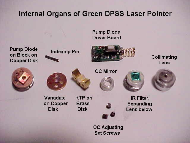
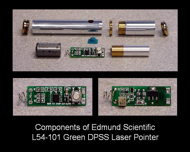
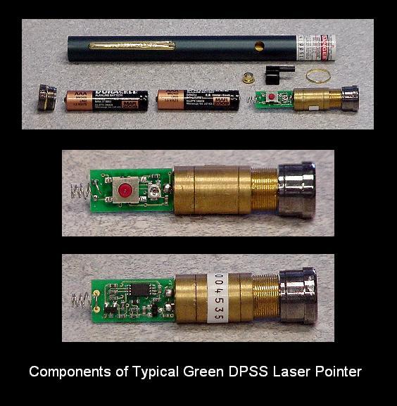
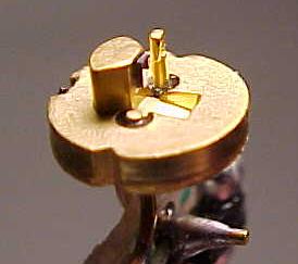
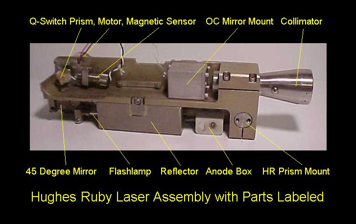
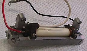
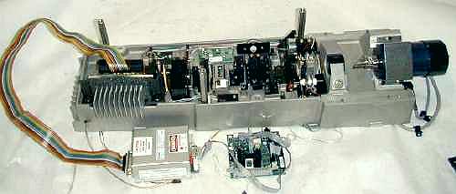
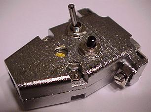
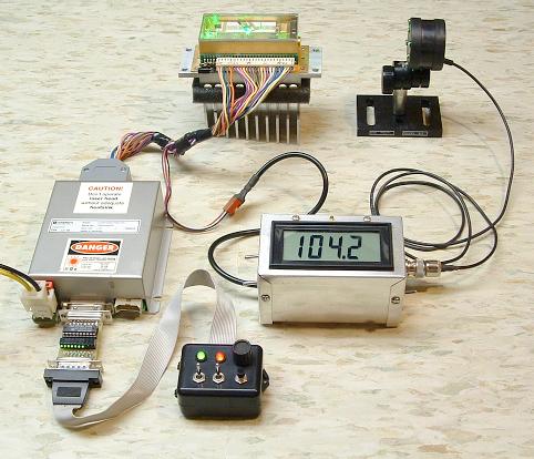
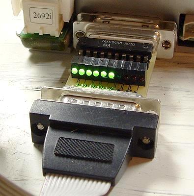
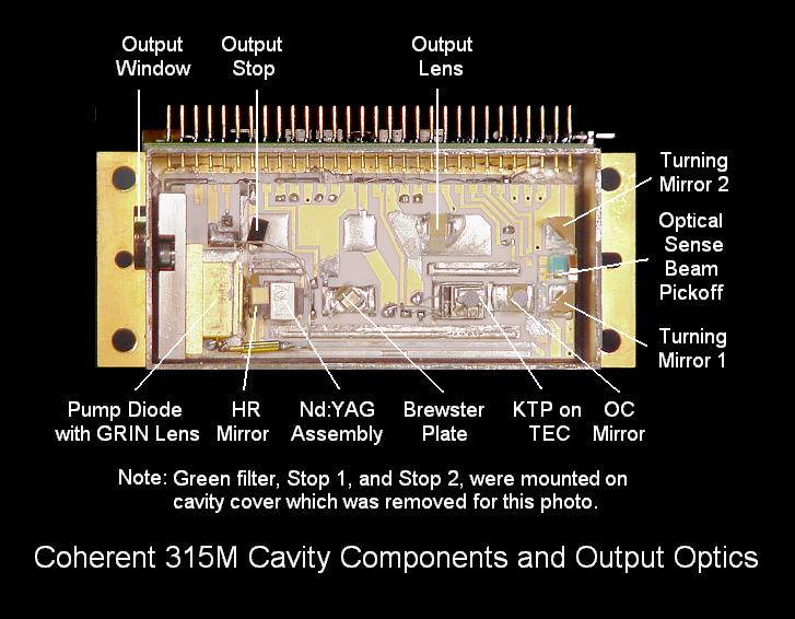
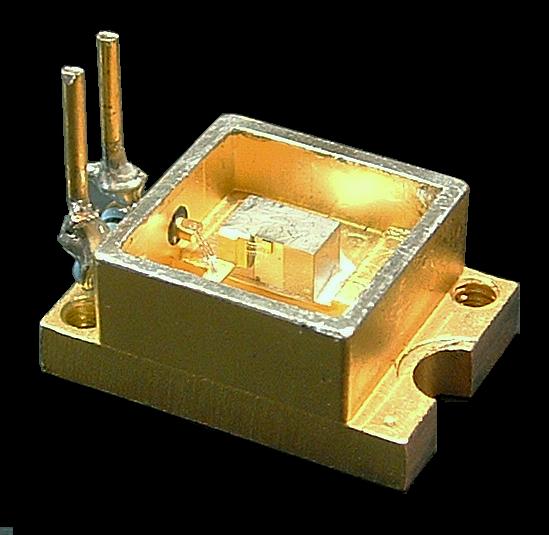
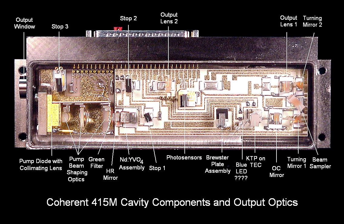
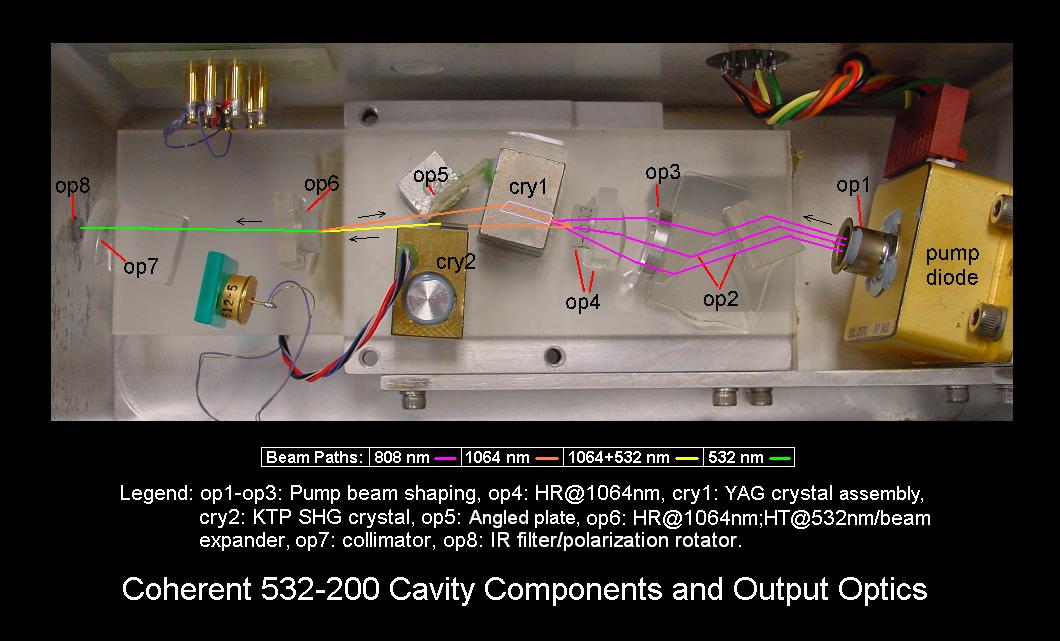
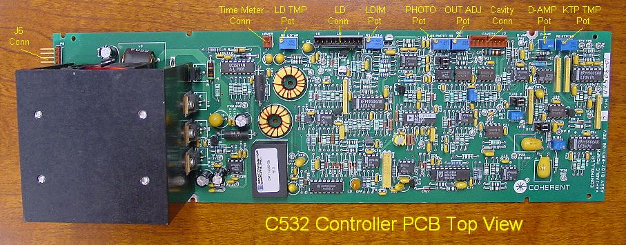
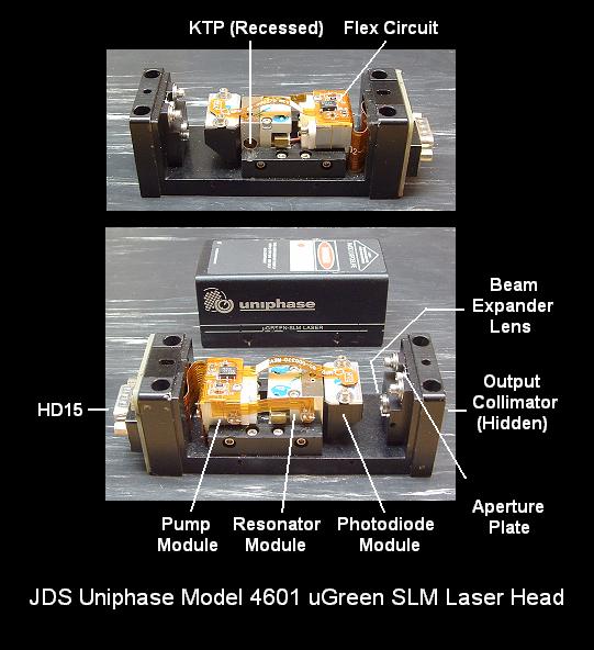
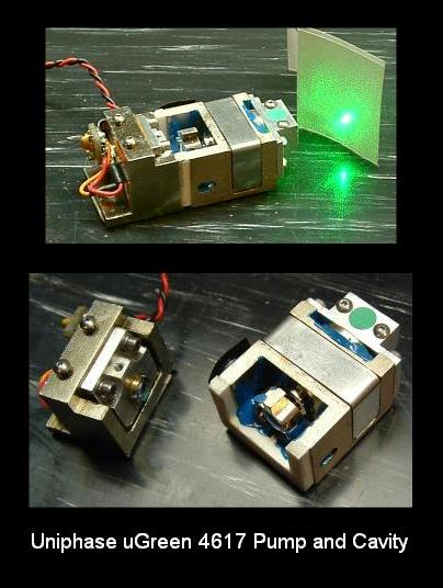
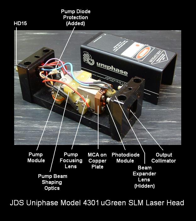
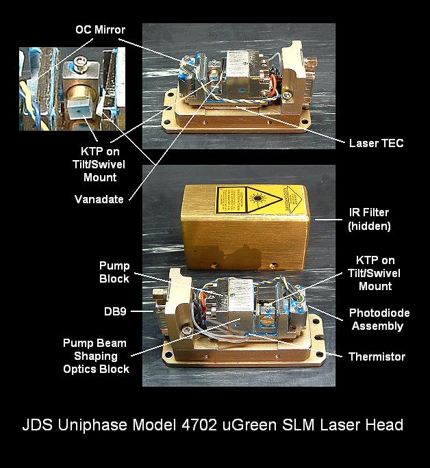
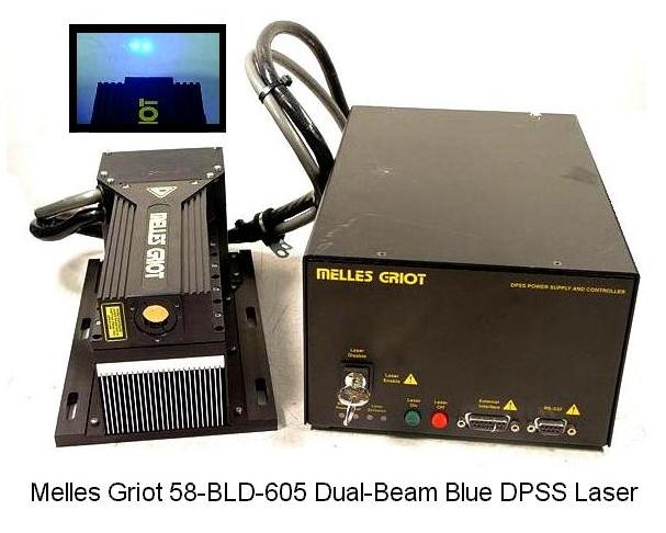
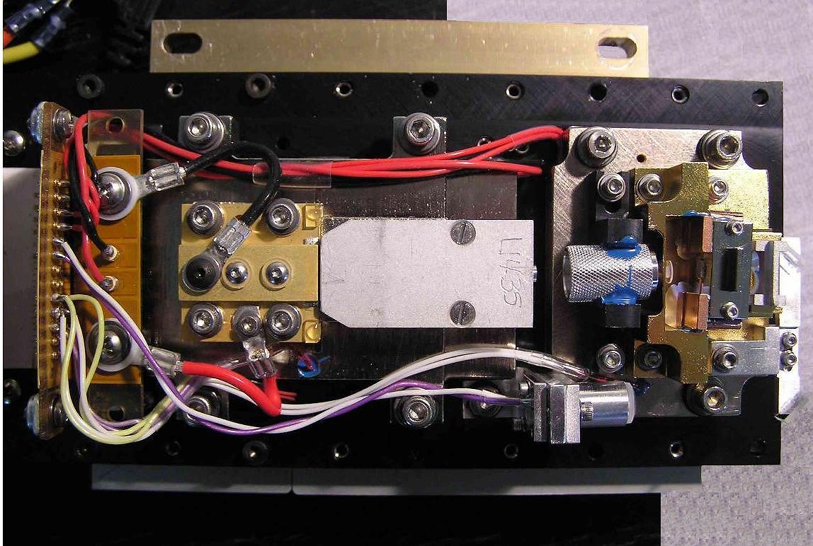
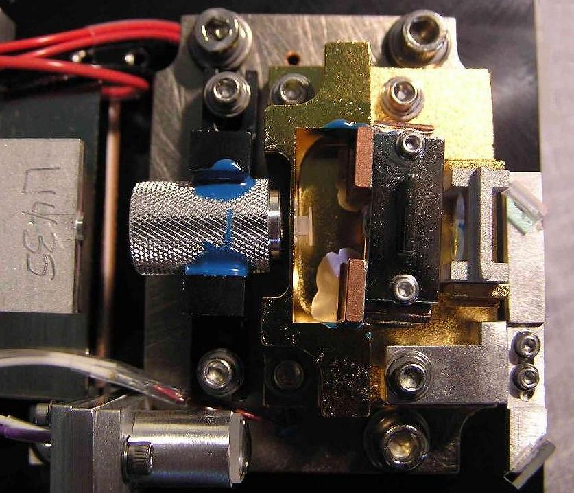
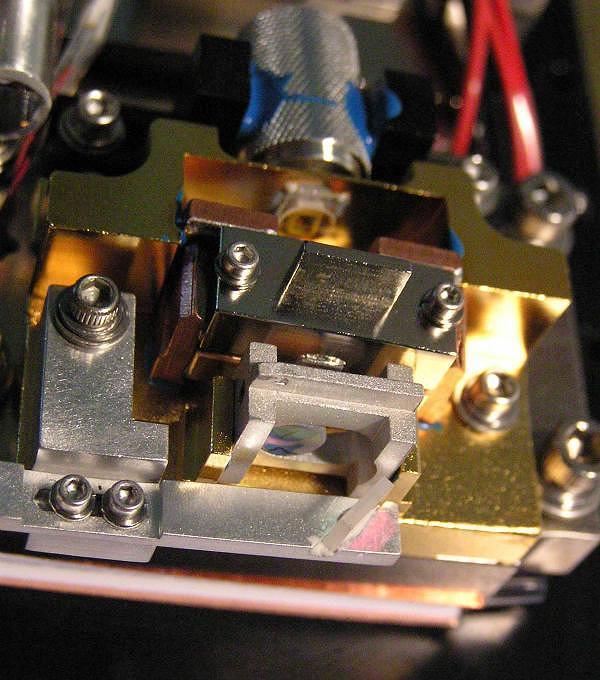
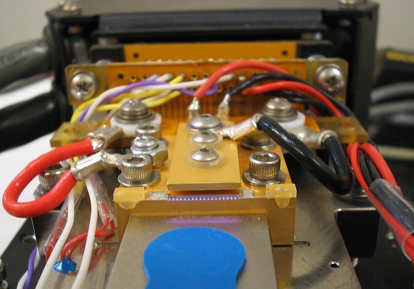
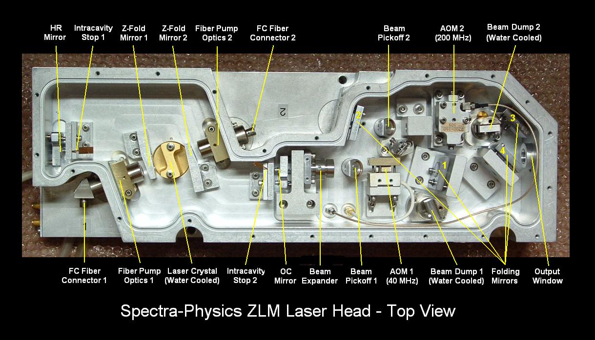
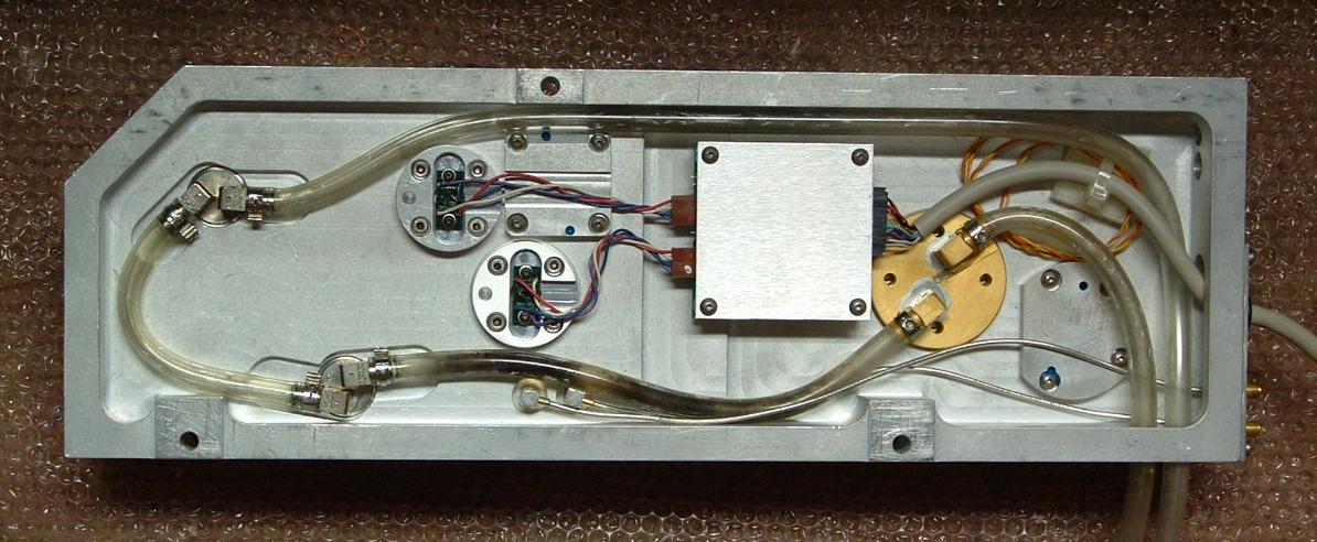