Since, the lifetime of the separate atoms is short, this must be repeated for each activation of the laser. This makes the power supply design a bit more interesting than the run-of-the-mill neon sign transformer! Also they are pulsed lasers but at a high enough repetition rate, the output will appear continuous.
This can be accomplished by a simple but brute-force motor driven distributor somewhat like that used in an automotive ignition or by a fancy sophisticated solid state power supply. The former looks and sounds like something out of a bad Sci-Fi movie (or nightmare, take your pick) but works!
A quasi-CW CuCl/CuBr laser can also be built (and this approach may be used commercially). At a repetition rate of several kHz, enough copper ions exist in the dissociated state so that lasing occurs on every pulse. Building a suitable pulsar is, however, left for the advanced course. :)
Output wavelengths are green (510.6 nm) and yellow (578.2 nm) and the pulses can be quite intense!
Like the N2 laser, CuCl and CuBr lasers do not need a resonator to operate. The design in "Light and its Uses" uses a mirror at one end and an *unsilvered* piece of glass at the other (output) end. (Of course, plain glass will act as a partial reflector - reflecting about 4% at zero-degree incidence). Mirrors can be internal or external (the Sci-Am design used internal mirrors). Where they are external, optical windows at a slight angle seal the ends of the tube. The angle is just to minimize reflections that could affect the resultant mode pattern - it doesn't need to be (and probably shouldn't be) at the Brewster angle.
(From: Steve Quest (Squest@galileo.cris.com).)
Most lasers need to resonate to build up emission. However, copper vapor lasers would damage themselves if they were allowed to resonate. There is so much photonic emission you only need one mirror, the back mirror in the cavity of a Cu laser. One pass through the cavity is enough, Cu lasers produce hundreds of watts per pulse!
Avoid eye contact with the direct or reflected beam. This includes the 4 beams reflecting off the Brewster windows which may be quite strong.
(From: Rich (synergyvideo@hotmail.com).)
"My impatience made me fire up my pulsar to measure the rotation rate of the disk. Imagine my surprise to find that the plastic I used couldn't take the stress of 6,000+ RPM! After I got back from the hospital the other night with shiny new staples in both arms I found pieces of plastic stuck in 3 walls and 4 different rooms. Thankfully I at least had safety goggles on.... Needless to say, I'm a bit gun-shy at the moment with rapidly spinning disks, so I'm pursuing the solid-state power supply instead."
Provide proper warning signs for both the laser radiation and high voltage. Surround the mechanical pulser (if used) with a sturdy shield. Keep pets and small children out of the area and make sure everyone present is instructed as to the dangers. The use of proper laser safety goggles for the specific wavelength(s) of your laser are highly recommended.
For more information, see the chapter: Laser Safety. Sample safety labels which can be edited for this laser can be found in the section: Laser Safety Labels and Signs.
(From: Steve Roberts (osteven@akrobiz.com).)
It used a 25 mm quartz tube tube in a standard 30 mm lab tube furnace with flowing helium at 4 to 8 Torr. Although we now know that neon is superior for this task, helium is a heck of a lot cheaper. Mirrors are flat with a 100% HR and a 60% transmission OC. The discharge circuit doesn't have a peaking cap across the tube. That came later from other researchers and really boosts power. The halide is in a dimple in the middle of the tube.
Optimal conditions were: CuBr at 420 °C (measured at tube wall), 8 Torr of helium, 260 us delay between pulses at 5 Hz. See NNR Double Pulse Driver for Copper Vapor Laser. (This was redrawn based on Steve's scribbles from the paper. --- Sam) The left side thyratron in the schematic provides the dissociation pulse, the right side thyratron with smaller cap provides the lasing pulse. No attempt was made to optimize the circuit for a faster rise time according to the text. 5 grams of CuBr lasted for around 20 hours of operation.
They used aluminum blocks as electrodes and Teflon blocks and O-rings to hold the works together and hold the Brewster stems as well, thus having long inactive regions. The Brewster stems were separate Pyrex pieces with quartz Brewster windows attached with Epoxy.
This used a 2.5 cm diameter quartz tube in a standard lab oven, 30 cm long active region. The rest of the tube was constructed of Pyrex using standard quartz-to-Pyrex transition seals (usually rings of 6 different glasses in series) with Pyrex stems and tubular aluminum electrodes. Like the first desgin the cavity used planar mirrors and they were 1 meter apart. Both lines lased with 1.5 mR divergence, the beam diameter being limited to 1.2 cm by the Brewster windows. It would lase superradiantly without the mirrors. The rep rate was 30 Hz using an EG&G 1802 thyratron and a 0.2 uF cap on the dissociation side and a triggered spark gap and .012 uF cap on the lasing side. No details of the spark gap are given. Both sides charge through 1M ohm resistors and the 4 uH inductor is absent. Minimum voltage for the disassociation pulse is 7 KV and lasing is a 24 ns pulse, lengthened by gain passes between the mirrors. The optimal firing delay is 200 us. This laser operated at a temperature 550 °C using CuI.
See: Bernhard Gruber's Laser Construction Page for some photos of his CuBr laser, Marx generator based pulsed power supply, and more.
Although the complexity of this laser may appear at first to be greater than that of some of the others, the required skills at each step are often more modest so overall, the likelihood of success may be greater!
Refer to Typical Home-Built Copper Chloride Laser Assembly for a simplified diagram of the overall structure and power supply electronics.
(Only a single transformer is shown in the diagram - one may be enough!):
           Neon Sign     D1             R1
         Transformers +--|>|--+--------/\/\---+----------+------------o HV1+
           15kV,60mA  |  D2   |         R2    |          |
             T1,T2 +--+--|>|--|----+---/\/\---|----+-----|----+-------o HV2+
     H o---+ ||=||(           |    |          |    |     |    |
            )|| ||(           |    |          |    |     /    /    Outputs to
            )|| ||(       C3 _|_  _|_ C4  C1 _|_  _|_ C2 \ R3 \ R4   Pulser
            )|| || +--+      ---  ---        ---  ---    /    /
            )|| ||(   |       |    |          |    |     \    \
            )|| ||(   |       |    |          |    |     |    |
     N o---+ ||=||(   |       |    |          |    |     |    |
             |   | +--|-------+----+----------+----+-----+----+-------o HV-
             |   |    |
     G o-----+---+----+
                     _|_
                    ////
The mechanical motor driven pulser/distributor discharges C1 and C2 through
the plasma tube with a delay of about 150 us and a repetition rate of about
50 Hz.
The main recommendation for your first CuCl/CuBr laser is to NOT make significant changes to any of the basic specifications (dimensions, materials) of the laser assembly and power supply.
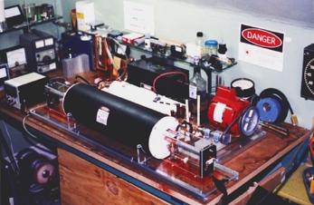
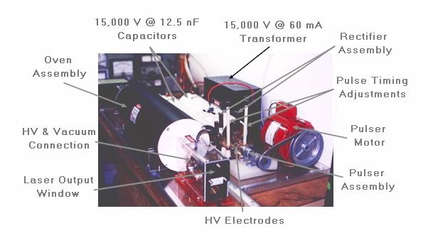
My copper halide laser is similar to the original article in "Light and its Uses" but with some updated components used in construction. For instance; instead of a quartz heater next to the plasma tube, I employed high temperature, laboratory type, heating tape wrapped directly around the plasma tube. This was purchased from AmpTek Company. I used the medium watt density, 1/2 inch wide tape. The 36 inch length is the perfect length for wrapping the 24 inch, 14 mm OD quartz plasma tube, covering 21 inches using closely spaced wraps. This product is capable of reaching 1400 F. The temperature of the laser is controlled by a process controller with a digital readout of the actual temperature via a thermistor mounted very close to the plasma tube. This unit was calibrated using a temperature probe inside the plasma tube before the laser was completed.
The plasma tube is constructed of heavy walled quartz tubing to avoid the possibility of the high voltage plasma arcing to the heating tape. The 2 mm fused quartz walls have a breakdown voltage of between 30,000 and 40,000 volts. Well above the 15,000 volts passing through the plasma tube. The Diagram of CuBr Laser shows the general construction details.
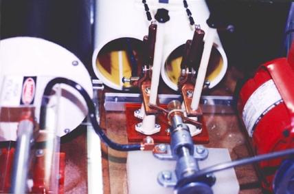
The high voltage power supply uses a mechanical distributor to double-pulse the laser at the required repetition rate. The motor (salvaged from a clothes dryer, I believe) is rated at 1725 rpm (but probably actually running close to 1800 rpm under these essentially no-load conditions). With the size if the sheaves I am using this has the pulser electrodes spinning at approximately 7000 rpm. This is something that can and should be adjustable anyway. The speed of the electrode assembly can affect this lasers operation. Just another parameter to play with to optimize this laser's output.
WARNING: The potential danger from the energy stored in C1 and C2 cannot be overemphasized! R1 and R2 are 100M ohm bleeder resistors rated at 5 W and 20 kV, which safely discharge these capacitors in about 10 seconds once system is shut down.
                     Neon Sign      D1
                    Transformer  +--|>|--+-------------+-----------o HV1+
     H o------+ T1   15kV,60mA   |  D2   |             |
               )||      T2   +---+--|>|--|------+------|----+------o HV2+
        Variac )<----+ ||=||(            |      |      |    |
        0-115V )||    )|| ||(            |      |      /    /    Outputs to
           12A )||    )|| ||(           _|_ C1 _|_ C2  \ R1 \ R2   Pulser
               )||    )|| || +--+       ---    ---     /    /
           +--+       )|| ||(   |        |      |      \    \
           |          )|| ||(   |        |      |      |    |
     N o---+---------+ ||=||(   |        |      |      |    |
                       |   | +--|--------+------+------+----+------o HV-
                       |   |    |
     G o---------------+---+----+
                               _|_
                              ////
Two pulses separated by 150 microseconds are needed to disassociate the copper from the halide and then excite the free copper atoms. This is repeated approximately 115 to 120 times per second (determined by the distributor motor speed and mechanical linkage). Low induction connections are needed between capacitors, pulser and plasma tube electrodes.
I am building a CuBr laser using a power supply based on a Marx generator. I use three, 2 kW microwave oven transformers connected to three-phase AC source and a three-phase (6 diode) bridge rectifier and 10 uF filter capacitor. The charging caps are made from 25 individual 2 nF, 7.5 kV ceramic capacitors soldered on two copper stripes (to keep inductance low and impulse current high).
There are some photos of portions of the system and other stuff as well as the power supply schematic at: Bernhard Gruber's Laser Construction Page.
The copper chloride (CuCl) laser produces powerful bursts of green (510.6 nm) and yellow (578.2 nm) light. Pulsed at 50 hertz the output appears continuous. I have been searching U.S. patents and have found a wealth of information on various types of metal vapor lasers. Great stuff!
I have just completed a home built copper halide laser. I decided to use copper(II) bromide (in helium) instead of copper chloride as the lasing medium. I had read that this copper halide was more efficient than the chloride. Also of interest is the addition of a small amount of hydrogen to the mix to dramatically increase output power. I have yet to try this, as I just obtained the copper(II) bromide. I was very fortunate to produce a beautiful, bright, green beam on the very first try. This is somewhat unusual with home built systems.
I am currently using a mechanical pulser (similar to the one described in the Scientific American article) to produce the closely spaced, rapid, high voltage discharges required for this laser's operation. This leaves something to be desired, as it is very noisy. I had considered the use of thyratrons for this application until I saw the price of these. (YIKES!!)
My copper bromide laser is very unique in many ways. It is certainly the first laser I have ever built that not only requires eye protection, but ear protection also. :-) The pulser, when in operation, is very LOUD.
It is very difficult to determine the power output of this laser without an expensive laser power meter. I unfortunately, cannot afford a power meter capable of reading such powers as this laser may produce.
I have been doing some more "playing" with this halide laser - experimenting to determine the effect of pressure on its operation. The laser seems to operate best below a couple of Torr. I was getting extremely bright pulses of both green and occasionally bright yellow, with a marked improvement in repetition rate. The beam diameter has also become much larger than it was at higher pressures. It still does not appear continuous but this may be able to be remedied by adjustments to the pulser.
All was going fine for an hour or so until one of my capacitors failed. I am using copper clad PCB caps and these are prone to dielectric breakdown every so often. There was a small hole blown through right at one corner. The potential at these sharp corners is more concentrated and this is usually where they fail. This makes for an easy fix, though. I have the damaged corner soaking in ferric chloride as we speak. It should be good as new very soon. I will be more careful in limiting voltage to these from now on. I guess I got a little carried away watching this beautiful beam become more stable at higher charging rates.
Chris Krah (Copper Chloride Laser Technology) and I have been conversing almost daily as to this laser project. As a matter of fact, I don't think I would have built this laser if it wasn't for his interest.
The thought of a solid state power supply is really what 'sparked' my interest. I was hoping I would not have to build a mechanical pulser for this project. Once the laser head was completed though, I just had to see it operational and couldn't wait for Chris to finalize his PSU.
(Questions from: Chris Krah (chriskrah@apple.com))
"Can somebody describe briefly how a copper chloride laser works? How hard/costly is it to construct such a laser? Is it appropriate for materials processing?"
(Replies from: Steve Quest (squest@cris.com).)
Briefly describe how a copper vapor laser works? :) Ok, I'll try.
First, you have a non-resonant cavity, just a Brewster window on one end and a full silver on the other. Heaters heat the cavity (vacuum) until the cupric chloride vaporizes inside. (Note: This differs from the recommendation in SciAm and elsewhere to put a low reflecting mirror like a microscope slide at the OC-end. --- Sam) A high current, high voltage discharge is fired through the cavity to dissociate the Cu from the Cl resulting in free copper vapor without the need to heat copper to the boiling point. At this time (very quickly after the dissociation pulse) another pulse is fired to excite (pump) the copper atoms. Spontaneous emissions that hit the mirror and fly back through the cavity stimulate the laser emission which exits the Brewster window. Such lasers are incredibly powerful, and the wavelength is visible in the yellow band.
"That means copper chloride laser and copper vapor laser are identical."
Yes, they are. :)
"What type of mirror is used: plano or concave?"
The answer should come to you if you do a ray-trace. Plano is the only mirror choice that makes sense, as concave would redirect much of the photons into the wall of the cavity.
"How "good" does the vacuum have to be? (Please tell me it's not a total vacuum such as in vacuum tubes). Do you need a vacuum at all? (It would certainly reduce the efficiency)."
You need to get the air out, all nitrogen and especially oxygen. A good vacuum produced with normal vacuum pumps (like when you pump down an argon tube before re-gassing) is good enough.
"What kind of heaters are used? I would think that an induction heater would do."
Quartz halogen heating elements, a quartz tube for the cavity, and insulate the thing well. It takes a lot of heat 600 °C if I remember correctly, to bring cupric chloride to the vapor state. HOWEVER, using this method prevents you from needing to bring copper to the vapor state, an act that would be impossible inside a quartz cavity (the quartz would melt and suck in way before the copper vaporized.
"What if you turn of the laser off ? Do you have to evacuate the Cl/Cu or does it turn to copper chloride when you cool down the cavity?"
Once the laser fires (single pulse), the cu and cl recombine, and the next dual-discharge dissociates and excites for the next pulse. This rep rate can run as high as 300 Hz, but slower is better, if I remember correctly. When you shut down the laser, the cupric chloride redeposits as a solid on the glass of the cavity (on the walls) and waits until you heat it back up again. My prototype was purely experimental, and the output power amazed even myself! And I'm hard to impress anymore. :) However it's been a few years so much of my memory is fog these days. ;)
"Seems awfully hard to construct."
I thought it would be, but it wasn't so bad. The gold beams are intense, quite a sight to behold! If you're into beam shows, this is your laser of choice, much better than an arc-lamp pumped Nd:YAG with a KTP doubler. :) Uses about half the electricity to produce twice the beam!
(From: Chris Krah (chriskrah@apple.com).)
Thanks for your quick response. :)
So in summary a copper vapor laser would consist of the following components:
The quartz cavity would be equipped with:
The time gap between dissociation pulse and excitation pulse should be dependent on how fast the chloride and copper atoms recombine to copper chloride.
I assume the power output should be dependent on:
Is there a rule of thumb to estimate the power output?
Power supply:
Copper vapor is a high gain medium meaning you can make them fairly small, although, even with limited space, I doubt there would be a hell of a lot of difference in the overall size of an amateur built laser that was putting out 10 W, or a few hundred milliwatts.
Here are some general guidelines for high power copper vapor laser construction:
The above information has been gleaned from LLNL's AVLIS program (the early years). The largest CVL they made had a 7 cm bore, and was just over a meter long. it produced nearly 90 W of green as an oscillator, and they were able to extract 120 W of power out of it in a MOPA (Master Oscillator Power Amplifier) configuration. With copper vapor's high gain, if you don't want to scale the laser, you can always build a power amplifier.
(From: Sam.)
I think I have a (reject) mirror from that or a similar LLNL laser, rated for 1,000 W(!!) and it is quite spectacular: Over 76 mm in diameter coated for 99.996% reflectance in the range 511 to 578 nm, 1/20 wave surface finish. Need I say more. :) The only defect is a tiny internal fracture near one edge which doesn't affect anything optical. I have to be sitting down to just think about the original cost of that mirror. :)
(From: Steve Roberts (osteven@akrobiz.com).)
It's a hump shaped curve. You can increase it too much. Are you running pure copper or a halide? Is your discharge self heated? Don't forget that the buffer gas also has a large impact out output power. The buffer gas transfers energy to the copper via collisions when it's excited (sort of like the function of the helium in a HeNe laser). You can't use air or nitrogen, as they will combine with the copper - it will burn. Acceptable buffer gases are the inert gases neon, helium, and argon, and neon which produces the greatest output followed by helium. Argon produces a much lower output power. Assuming your in the USA, helium is cheap in welding grade gas, about $80 to purchase the tank and $15 a refill.
You need to be hot at all times, it depends on your tube construction. You may need to reduce the heat, but without a professional pulser running at 10 to 20 kHz, you will need the heater. This depends much on your tube construction and what you use to insulate it. Ceramic wool from a lab supply catalog can take the heat and would be my choice for insulator.
There are different curves for copper vapor and copper halide lasers. The book you need is:
It's in English, Broken English translated by a Russian techie type, but usable. Every paper it references is Russian and thus probably unobtainium unless you have friends there skilled in spectroscopy. 300 dense pages. I got it on interlibrary loan, but I'm at a university and that makes it easy.
For one of their poorer examples:
They have about 1.5 to 2.0 kW average power measured at the rectifier. 300 ns pulses at 200 to 300 A but they use a carefully selected peaking capacitor across the tube, which is the real key to operation, i.e., a sloped rising edge. Rise time is 45 ns. That's for 2.1 W in a 12 mm bore and 3.75 W in a 20 mm bore using Ne at 12 Torr in a 60 cm long tube. 10 kHz rep rate. Temperature is 390 °C using CuBr. It is not however a simple straight wall tube, but has disks. Output is approximately 3.5 W of green and yellow. Scaling the bore to 22 mm and raising the rep rate to 15 kHz resulted in around 7.3 watts from the same PSU. This is a resonator (with mirrors), not with just windows, in an external oven.
If that design was switched to Chris Little's HYBRID gas mix (CuBr with H2 in Ne), which was developed after the book was written, it would probably be even better. Little has the current record for CVL power per watt.
Their list of gases:
As in all books Russian, at least those before Capitalism hit over there,. it gives the complete details on everything. PSUs, tube seals, heating, the works. They get 7 to 20 watts from 1 meter long quartz tubes using copper bromide and external heaters. The secret is to scale the PRF high enough i.e., 14 to 20 Khz, that you don't need to do a double pulse. This of course means a thyratron and a pulse forming network, or in some cases two thyratrons in push-pull.
But, then we have the sealed tube CVLs:
(From: L. Michael Roberts (NewsMail@LaserFX.com).)
I own a 5 watt Spectronika copper vapor laser and it does not have brewster windows. It does not even have a front mirror. The front-end has a window on it (non removable as this is a sealed tube design). The back-end has a window with a mirror mounted on a metal ring. This is a copper bromide system using a multi-kHz pulse excitation.
Spectronika sell the replacement tubes for their laser for only $1,650 so it might almost be worth it to buy the tube and build the supply yourself.
The following technical information is from: CRC Handbook of Chemistry and Physics, CRC Press, 56th edition.
400 °C is only 752 °C and not 1,400 °F, but the melting oint of CuCl is 430 °C or 806 °F and the boiling point of CuCl is 1,490 °C or 2,714 °F. This, of course requires a temperature equal to or greater than 810 °C or 1490 °F to be the optional point at which enough CuCl vaporizes under non-standard STP for lasing to take place. It may be interesting to note that the point at which CuCl boils is obtainable with a quartz tube, since the exact melting point of quartz is 1,610 °C or 2,930 °F. For comparison, iron melts at 1,535 °C or 2,795 °F, or just after the boiling point of CuCl.
Here are some notes about refactories and gas fired approaches.
So just for fun, what would withstand these temperatures? Well, the answer is that plane old Portland Cement makes an excellent high temperature refactory when mixed with ground yellow fireplace brick (Denver Fire Clay) and applyed in thin layers of less than or equal to 1 inch thick with carved/shaped/worked fire brick as the supporting structure. In other words, the Portland paste as the heat shield for the Denver Fire Clay, as the latter will melt down at about 2,500 °F (orange/yellow heat) but an inch of the Portland-Fireclay mixture will protect it completely in yellow/white heat. Blast propane and compressed air into the cavity and you can now completely vaporize the cuprous chloride and maybe run the laser at slightly higher pressures. Just remember to protrude extra quartz from the fire box as not to burn the tube seal. How good is calcium aluminum silicate as a refactory? 3,200 °F, about the hottest you could ever get with propane and forced air from a straight piece of steel pipe. The temperature can be controlled by adding too much gas to too little air or visa versa but too little air is much better as it keeps oxidation under control, and I have never had any problems with the refractory paste except if I were to spill other reactive superheated fluids on the hardened mixture which would cause it to break down requiring spot patching. I never had it explode, but it will crack if it's too thick. It might also be interesting to know that 2,500 °F can be reached with most Nichrome heating elements, but after long runs at peak temperature the elements will harden. So make the box such that the elements are supported and expect to replace them every 200 hours. The real trick to getting high temperatures out of electric elements is using highly reflective refactory like ceramic fiber "fluff" resembles R11 insulation but more dense, or use more elements. If you asked me what the best refractory ever is, I would say the fluff: it can be blinding white hot then warm to the touch in about 15 seconds. If you use "fluff " for anything keep in mind that serious unexpected peak temperatures are possible that you wouldn't have expected because of its excellent ability to reflect heat yet remain hot on just the surface. It is this property that allows the entire furnace to reach heat soaking of within 95% of the peak temperature of the heat source even if the heat source is small. I tend to use fluff whenever possible and Portland cement makes a good adhesive for the "fluff" as well
For more fun... It sure would be nice if the boiling point of copper was not 2,567 °C which is an amazing 4,652.6 °F and is equal to the filament temperature of a 120 watt light bulb! One other interesting fact is that most forms of copper chloride decompose at red heat back to the simple CuCl we have all come to love.
Here is a list of those that decompose when heated to 800 °C:
And I now part with this question: What is the best sealant that can withstand temperatures of greater than 400 °C? for anyone that may read this and knows the answer.
I need to design a high voltage pulse transformer. Input voltage is about 200 V (at several 10s of amps). Output voltage 20 kV. The pulse transformer needs to step up two closely spaced 50 us wide pulses (pulses are spaced at 200 us). The problem: The HV pulses at the output of the transformer have to be sharp edged just like the input pulses. A regular ignition coil won't work. The pulses appear as one wide pulse at the output. Therefore I guess it is necessary to build my own pulse transformer. My guess is: Use core material with low permeability to keep in and output inductance low.
(From: Bill Sloman (sloman@sci.kun.nl).)
Of course, if you want to preserve the sharp edges you need a transmission line transformer. These can be designed to produce integer step-up ratios - see: R.E. Matick, Proceeding of the IEEE, volume 56, pages 47-62 (1968). However, I've never heard of one designed for a 100:1 step-up.
Two 10:1 stages might be practical, and three 3:1 plus a 4:1 get you back to familiar territory, though with 5kV between the turns, the top transformer probably has to be wound with good quality RG58CU.
The other advantage of transmission line transformers is that you can use high permeability material for your core, since this only has to handle the low-frequency droop.
The disadvantage is that it is an incredible pain to comprehend what is going on - but Winfield Hill seems to understand them, so it is humanly possible.
For the life of me, I can't work out whether you could get away with toroidal strip-wound cores. Classical high voltage pulse transformers used soft-iron wire cores, but I don't know if this is relevant. I once found a nice text on the subject in the Southampton University library in 1972, which I remember as "High Voltage Pulse Technology" by Frugnel, but after 25 years this can't be relied on. There certainly isn't anything with this title in the Dutch academic library system.
(From: Chris Krah (chriskrah@apple.com).)
A 100:1 step up transmission line transformer would require 10 transmission lines. Please correct me if I am wrong. I found this on the web: Transmission Line Transformers. I am not sure how feasible it is to construct a transformer like that.
Is there a good book that explains (pulse) transformer design in easy to understand terms?
I would appreciate any suggestions you may have.
(From: Jerry Codner (gcodner@lightlink.com).)
Sounds like fun. What's it for?
(From: Chris Krah (chriskrah@apple.com).)
This is part of a power supply for a copper chloride laser. Conventional power supplies use a mechanical chopper to generate the pulses. The mechanical chopper looks similar to a rotary spark gap used in tesla coils (neon sign transformer + rectifier + HV capacitor + chopper). I was looking into more elegant solid state solutions. I have figured out most of the parts for this power supply, except the transformer. I have posted some waveforms and schematics on Chris Krah's Web Page. I would appreciate any feedback you may have.
(From: Jerry Codner (gcodner@lightlink.com).)
Your problem with the ignition coil and with any transformer of this type will be leakage inductance, but 50 us pulses at a 5 kHz rep rate isn't too bad. How about flyback transformers? Essentially they are pulse transformers. You picked a 20 ohm load impedance (200 volts/10 amps) so magnetizing inductance should be 200 ohms or more at ~1/(2pi*50 us) = 3.2 kHz.
(From: Chris Krah (chriskrah@apple.com).)
Actually the input current will be much higher than that as the output peak current is in the amp not mA range.
(From: Jerry Codner (gcodner@lightlink.com).)
How sharp do the edges have to be?
(From: Sam.)
Marco Lauschmann (mq-laser@gmx.de) has pointed out that the 10 us figure for pulse rise times quoted below is much longer than desired for the CuCl laser:
"The copper vapor laser needs sharp edged HV pulses, with rise-times in the 100 ns range! Power will be maximum at about 50 ns. It will still work with a rise-time of 200 ns but the power will be much lower."
Therefore, the discussion below should be used only as a means of identifying some of the relevant circuit design issues and possibly the basic math, not for determining actual numbers or selecting components.
(From: Chris Krah (chriskrah@apple.com).)
10 us rise/fall time max.
(From: Jerry Codner (gcodner@lightlink.com).)
That will determine what the leakage inductance and secondary winding capacitance must be. You will need to provide enough insulation for 20 kV isolation (you should use 50% to 100% of the operating voltage in the insulation thickness calculations) and the extra spacing increases leakage inductance.
(From: Chris Krah (chriskrah@apple.com).)
I thought of immersing the transformer into high voltage oil such as Diala AX from Shell.
(From: Jerry Codner (gcodner@lightlink.com).)
If we use 10 mH for the magnetizing inductance, obtained using a gapped core, then a 200 volt input pulse will generate 1/2 amp of magnetizing current after 50 us. The gapped core is required to linearize the magnetizing inductance and to provide for dc current since the input pulses are unipolar.
[Aside: You specified that the waveform as a capacitor discharge, if the RC time constant is 50 us, then the final current is also 1/2 amp. That's because the current is the integral of the voltage and the integral of an exponential is equal to the initial value times the time constant, as though a rectangular pulse were applied.]
For 10 us rise time, you need leakage reactance much less than R = 20 ohms or L/R less than 10 us. For L/R = 1 us, L = 20 uH. That may be obtainable, but you will have to keep sqrt(LC) below 1 us also and that will require C < 1 uF. With a 100:1 turns ratio, C = 1 uf is within reason, but remember it's the secondary capacitance reflected to the primary so that's 1uF/1002 = 100pF of secondary capacitance. A one layer secondary would be good, but you are cranking out a bit of power (2 kW), so the conductors must be sized for the peak current of 10 amps/100 = 0.1 amp and an rms current of sqrt(50/200)*0.1 = 0.05 amperes. If the pairs of pulses are more widely spaced than this, then resistance rather than rms current will detect the conductor size.
(From: Chris Krah (chriskrah@apple.com).)
Isn't the gapped core also important to prevent the core from getting saturated?
(From: Jerry Codner (gcodner@lightlink.com).)
Secondary capacitance is reduced by using tall, narrow windings, but this increases leakage inductance. You will need to explore winding configurations to find the optimal one for your situation. I would start with a concentrically wound pair of windings, secondary over primary over core before advancing to interleaved winding schemes that can lower leakage inductance but then pose trickier voltage isolation problems. You need to keep the primary turns low, so a high permeability core is essential, especially since it will be gapped, thereby reducing the effective permeability.
If you can, the entire assembly should be immersed in dielectric fluid, e.g. FC-77. Otherwise, you may have some severe insulation breakdown problems due to corona.
(From: Chris Krah (chriskrah@apple.com).)
How about using e.g. 4 separate transformers, put the primaries and secondaries in series. This way output capacitance and leakage inductance could be minimized. Isolation would be much simpler this way.
I started hunting for more info on copper halide lasers and found U.S. Patent #4,275,317: Pulse Switching for High Energy Lasers by Laudenslager et al., June 23, 1981. It contains a really good description of how a pulse forming network operates to produce multi-kV pulses with 10 ns rise times, and also why such steep rise times are advantageous in driving moderate to high pressure (e.g., excimer) laser systems.
This would appear to have significant relevance to driving a CuCl or CuBr laser which requires two fast rise time pulses 150 us apart. It offers the possibility of a totally solid state, SCR based power supply which is relatively cheap and robust).
(From: Chris Krah (chriskrah@apple.com).)
You need 2 triggered spark gaps. The spark gaps operate at 10 to 15 psi air pressure for better quenching.
You need 2 Neon Sign Transformers (NSTs) and 2 charge capacitors. Each charge cap is directly connected to the output of the NTSs. No HV diodes are necessary. That's the beauty of the system. The caps are charged via 60 Hz cycle (similar to the setup in a tesla coil). The charge cap will form a low pass filter with the impedance of the NST. The cutoff frequency of the low pass filter is 60 Hz. Therefore the value of the cap can be calculated as follows: fcutoff = 1/(2PI*Z*C) -> C = 1/(2PI*Z*fcutoff). Z is the impedance of the NST and is equal to U/I where U is the open circuit output voltage of the NST and I is the short circuit current of the secondary.
The caps are consecutively discharged into the cavity of the CuCl at both peaks of the 60 Hz cycle. Therefore, the laser will operate at 120Hz.
The flyback transformer from a B/W TV or monochrome computer monitors can be used to generate the trigger pulse and a monostable like the 74LS221 can be used to provide the delay. These have low jitter and are continuously adjustable. The wiring is simple with a minimum of external components. To generate the trigger pulses, rectify low voltage AC via a bridge rectifier and apply this to a peak detector (diode in series with cap, the cap will be charged with the peak voltage minus forward voltage of diode). Pass the rectified AC to the non-inverting input of a comparator, the peak voltage to the inverting input. The comparator will generate your first trigger signal. The latter also triggers the monoflop. The monoflop will generate second trigger. The trigger signals are feed to the flyback trigger mechanism (SCR based).
I know of a gentleman who has used this system successfully. Operates quietly and can be tuned by adjusting the pulse spacing. Quasi-CW CuCl/CuBr Laser This certainly sounds like the way to go but the power supply may be very non-trivial, not to mention, even more deadly than the mechanical pulsar.
(From: Steve Roberts (osteven@akrobiz.com).)
Once upon a time everybody was trying to make homemade double pulse copper vapor lasers using CuCl or CuBr. Thats a major goof. I just got the definitive Russian book on CuBr lasers on interlibrary loan. You have to go the other way. Run them at several kHz in a quartz tube in a oven. Then you don't need the double pulses as there is enough halide in the split state that way - some of it recombining, some of it lasing. The power supply needs about 14 kV at an amp or two. A close examination of a Spektronica CVL at the Laser F/X conference confirmed it was running this way, at about 14 kHz.
Having just finished construction of a copper halide laser, I would hardly call it an "easy" laser to build. Although this laser does not require the use of expensive optics as some do, you must still have a vacuum system and related apparatus, a source of helium, a way to accurately control the plasma tube temperature at 400 C, a high voltage power supply capable of producing two quick, accurately timed pulses at a high repetition rate and other items which make this project somewhat more difficult than other types of lasers featured in the Scientific American articles.
(From: Ken Donnell (kdonnell1@earthlink.net).)
If you want high output but are afraid of sophisticated optics and can handle complex electronic design, try a copper vapor laser. I managed to hack together a TEA copper vapor unit in only a few days by using an acetylene torch to vaporize copper and blow it past a spark gap. This was obviously only useful for short operating runs but produced over a watt of 510 nm and 578 nm. A high power version of the Blumlein circuit used in N2 lasers was all that was needed to trigger it.
(From: James Lockwood (james@foonly.com).)
I've been experimenting with both arc and oxy-acetylene heating of copper (as an electrode with the arc and in a crucible for gas heating), attempting to sidestep the high temperature issues within the discharge chamber. It's pretty simple, just blowing monatomic Cu vapor and neon past a pair of long electrodes with a mirror and OC at the ends. Exhaust goes into a chilled vermiculite (flaked mica) substrate.
Obviously useless for long operating runs but still fun. It's not very reliable, though, which is why I'm hoping for more detailed information on how pressure and buffer gas mix affects operation. I've found quite a bit of copper halide laser information online and in libraries, but very little on TEA designs.
It uses pure copper vapor heated by a secondary arc (using carbon rods) and carried past the primary electrodes by the injection of (Ne) buffer gas. It's an extremely hacked-together design built over a couple of days purely as a proof of concept. I'm not much of a laserist but I am experienced at high voltage design and this was trivial to assemble.
The copper chloride laser will operate at the easier obtainable temperature of 400 C. The gain on this type of laser is very high and specialized optics are not necessary for successful operation. A simple microscope slide will act as an output coupler. The operation of this laser does depend on a pair of closely spaced high voltage discharges, which may be the most demanding aspect of building this system.
(From: Steve Quest (Squest@cris.com).)
True, you need only one mirror in the Cu Vapor laser. True as well about the high voltage pulses, which the differential time between the two pulses HAS to be relatively exact, but this is not as hard as it seems, as the timing can be done with cheap digital logic chips (decade counters, and dividers) or with a programmable microcontroller to get the timing exact. The *real* danger is the voltage AND the current are both very high (read: lethal) so you MUST BE CAREFUL around them...........
(Ever seen a squirrel come across a 13.7 kV high wire power line? Well, you'd be that squirrel. :)
(From: L. Michael Roberts (NewsMail@laserfx.com).)
The source of all this wattage is a pair of Oxford Laser ACL 45 Copper vapour lasers complete with a pair of British technicians who start up the lasers and then leave for the hotel. These lasers have an output power of 45 watts in pulsed mode with a repetition rate in the 5-10 kHz range and a beam diameter in the 40 mm range. The beam diameter is intrinsically large as power output scales with the volume of the plasma. While these specs would be a nightmare for scanned graphics applications, they are perfect for beam effects.
While both CV and YAG lasers are pulsed making them unsuitable for graphics, they have high power and high brightness and are ideal for beam displays. At present, it is much simpler to set up and run a 50 watt YAG then a 50 watt CV laser. Where the CV does win is the striking emerald green and gold colours while the YAG is that harsh lime green.
Copper vapour lasers do not use a permanent gas fill as in argon and krypton ion lasers. The lasing medium is a monatomic metal vapour obtained by heating a plasma tube containing a metal charge using power from an electric discharge. The discharge runs between electrodes at each end of a refractory ceramic tube which is thermally insulated inside a vacuum envelope. The heat generated by the repetitively pulsed discharge raises the temperature of the tube sufficiently to vaporize the metal charge loaded along it's length. The pulsed discharge then begins to excite the metal vapour in preference to the flowing buffer (neon) gas and lasing action begins.
However with the flowing gas design, the wide 50 mm beam, their size and weight, and their need to be fed copper rods at regular intervals, these are not exactly ideal touring lasers.
For more information see the "LaserBasics" article on Copper Vapour Lasers which is part of the paper: "Blinded By The Lights - Pink Floyd On Tour" from which the above summary was extracted. This is accessible from the LaserFX.com Archives and Download - Archives Page of LaserFX.com.
You can find some pictures of a Cu vapour laser in action at the Laser F/X Newsletter Special Report - Saturday May 29, 1999 and some more info about the Spectronika laser at the Laser F/X Newsletter Special Report - Sunday May 30, 1999.
There are now small, cheap, sealed tube design, air cooled CV lasers on the market with up to 5 watts of power. One such unit from Spectronika sells for about $7,000. The tubes last 700 to 800 hours and then are cheaply replaced. (Well everything is relative - $1,650 for the replacement tube.) The disadvantages are that they are pulsed and have a 14 mm beam diameter. None the less, I expect to see many of these entering the entertainment market shortly due to their reliability, colours, low cost, high power and ease of operation. Compare that to argon ion laser prices!
Since this is a commercial product, I doubt that the manufacturer would be giving away the schematics. However, Spectronika does sell the replacement tubes for this laser for so you may want to consider buying a tube then building your own power supply.
From: Patrick Dietzel (patrick@dietzel.net).)
One could calculate +9 spare tubes in from the start so your laser will safely work for 7000 hours and costs $ 22k. Isn't too bad for 5 Watts sealed air-cooled unused special, is it? It is also more reliable than a one-tube solution. If the tube breaks or leaks you have a new one at hand immediately. ;-)
(From: Steve Roberts (osteven@akrobiz.com).)
That's right, the CVL economics are comparable if not better then the ion laser economics.
I have seen the Spektronica unit and the thing is beautiful. A tube change out would be a no brainer, unlike the 4 to 5 delicate hours of brain surgery it takes to replace a delicate ion tube, during which time if you sneeze or even sweat or have a tremor in your hand it could cost you dearly, either in terms of output power or that $700 optic that just rolled off the bench or won't clean up. The CVL tube has no fragile appendages, Brewster stems, and the only cleaning is the OC face. There are no magnets, no leaks, no fragile ballast feeds, and no major regulator circuitry. The CVL just has a on/off switch, no current controls, etc. Thats one less failure, and the club staff can't burn out the tube early by cranking up the power. (Hint: If you're selling a laser to a club, open up the PSU and set the current limit to a little above the optimum current for the tube)
For those who haven't done it, a large frame ion laser tube change is very stressful, even if you do it every few days in a refurb shop. One wrong move and your writing your customer a $5,000 to 17,000 check instead of getting paid. One little water leak, and you find yourself doing about $500 in parts and a few days labor redoing the PSU. Having factory service do it for you is going to cost you $300 a hour, minimum $1000, plus travel costs. That's why professional ion repairs are pricey, its not easy.
Another bonus is you get a new set of optics every change. 700 hours might not be that long in a club situation, but figure in that at 1,500 hours in a filthy club (I dare you to tell me there is a clean area backstage in any club, except where they count the money) an ion tube is down to way below initial power and getting quite dim. The external cavity optics, no matter how well sealed, are shot. That's $1,400 right there. Lab grade Ion doesn't mechanically hold up or stay stable when its got 6,000 watts of subwoofer setting beside it either. That's why industrial lasers that are sealed mirror or auto-tweek themselves are a blessing in a club.
Club owners are typically cheapskates, unless its a major corporation that owns the club. Few of them understand planned maintenance. The club owner might fork over enough for a refurb, but odds are he won't pay for a new tube, and you'll find yourself out of a job if you tell him its 13,000$ to fix it. More likely he'll find another laserist who will buy him a cheap used laser from some university and put it in, and he'll call you and say, "Ha ha, I got the whole thing new for $5K." Unless it appears majorly dim, he'll accept the used system on the basis of economics. Been there, done that, got the T shirt. :)
Being told its $1,700 for a new drop in bulb is something am owner might understand, especially when some of the HMI and Arc lamps in his intelligent lighting fixtures cost around $400 to 500 each.
Also the gold and green from a small CVL have a very distinctive look, much nicer then the lime green of 532 nm, and when the beam is still combined, it looks a lovely golden white color, as when the eye is saturated with yellow and blue-green it sees white.
(From: Leonard Migliore (lm@laserk.com).)
Another application for copper vapor lasers is micromachining:
I use a CVL from Oxford.
The optimal pressure is 3 to 10 mbar for helium and 7 to 30 mbar for neon. (1 mbar = 0.75 Torr.) It is important for a good discharge and also for good overall efficiency that you use high purity gases.
Before I use the laser, I pump down the system overnight (at least 6 to 8 hours) with the built-in single stage rotary vacuum pump to less than 0.01 mbar. Then I control the system for leaks and fill in the buffer gas (neon 4.5). I think, it is important to pump down the tube 2 to 3 decades lower than the operating pressure to clean the tube of contaminants. With a pump reaching only the operating pressure, I think you can not clean the tube as thoroughly as required and the discharge may not be stable.
When the laser was unused for a longer time (2 to 3 months or more), I filled the tube 2 to 3 times with helium (because it is cheaper than neon) to atmosphere pressure and pumped them down again also to clean the tube of contaminants. A heated tube will be helpful to do this but is not a must.
The helium discharge should be a pink color. This indicates a clean discharge (with neon it is orange-red). The discharge should be stable in the center of the tube.
Output power at the green wavelength is nearly the same using helium or neon, but neon produces a stronger yellow. The green:yellow ratio is dependent on plasma tube temperature. Higher temperature results in less green and more yellow. A ratio of 1.5 to 2 times green versus yellow is optimum (discharge around 1,500 °C). To much yellow is also possible at lower temperatures, when the discharge is not clean enough.
A short pulse width is also essential to achieve optimum output. Measure the discharge pulse at the tube with a frequency compensated high voltage probe (Tektronix P6015, 40 kV, 150 MHz). You need a pulse width between 20 to 50 ns. When the discharge is to slow, the output power goes down.
Used for 425 hours of lasing then placed in long term storage.
Output Specifications:
Unit is in excellent condition, but is slightly dusty from storage without cases.
(From: Daniel Kapitan (dkapitan@jesus.ox.ac.uk).
Being one of the few copper laser junkies in the world, I was just wondering what this one has done in the past. Also, it seems to me a bit unusual that you can span the whole frequency range from 0 to 10 kHz. Surely your laser will have died if the pulse rep gets below 1 kHz?
BTW, what the going rate these days?
(From: Brian Fluegel (bfluegel@nrel.gov).)
I agree that a copper vapor laser will die at rep rates below 1 kHz. It will also frequently die at rep rates greater than or equal to 1 kHz. As a graduate student, I suffered through four CVLs, and I could tell plenty of horror stories. Are you a CVL junkie voluntarily?
"I need a UV laser source, but I'm wondering about using some existing laser sources like Nd:YAG (1064nm), Ar +(488nm), Cu vapour (510nm). The trouble is, I've NOT come across anyone who has doubled the Cu vapour laser in any papers. Would that be a better option? Do you know of any crystals I could use for the Cu vapour?"
Ramsey at the University of Macquarie in Australia has reported on frequency-doubled copper vapor lasers (SPIE vol. 2062, pp22-29). There are several references in this paper to other work with doubled CVL's. Ramsey's group used BBO with the 510 nm line.
The copper vapor laser is an excellent pump for the a dye laser using R6G as the lasing medium. The 511 nm line of the Cu laser is a relatively good match to the absorption curve of R6G (its peak is at 530 nm). In a properly designed system, pumping efficiency should be close to 40 percent.
In fact, the Cu laser is an excellent pump source for quite a few of the dyes that lase from yellow to red. Rhodamine-620 is another one to try. :-) As the name suggests, it lases at a peak of 620 nm in the orange.
Also see the section: Home-Built Dye Laser.
Since the first high power pulses were observed at 510.6 nm from a copper vapor laser almost 30 years ago there have been many different metals tried with varying success. One of the more common types today is the helium-cadmium (HeCd) laser. Some others that have been fairly efficient but have not found widespread commercial value are: lead (Pb) vapor at 723 nm, barium (Ba) vapor at 1,500 nm, manganese (Mn) vapor at 534/1,300 nm and gold (Au) vapor at 628 nm.
However, although the melting point of a metal like lead is relatively low, the temperature at which adequate vapor pressure for laser action to take place may be quite a bit higher. For instance, a copper vapor laser typically must operate at 1,500 C but the melting temperature of copper is only 1,083 C. Metal halide lasers have the advantage of working at much lower temperatures, but because of the double discharge needed for their operation the power supplies are quite complicated.
(From: ralord@webmail.co.za.)
The lead vapor laser works with a He buffer and produces very powerful and short pulses of deep red with average powers of watts or tens of watts, the gain is extremely high, it is no less than 40 dB single pass for a 30 cm tube, and the laser works at 900-1000 °C with metallic lead.
A quartz tube is needed and so is a good high temp sealant and a way to condense lead vapor before it reaches output windows.
With it's exceedingly high gain this laser has no need for resonators or mirrors, a mirror would probably make it explode. :) They are superradiant lasers, just like the good old nitrogen laser. It looks like LVLs are much more efficient than CVLs and less demanding too.
(From: Bob.)
A lead vapor (i.e., atomic) laser can operate on at least 9 lines: 364 nm, 406 nm, 723 nm, 1,256 nm, 1,315 nm, 1,534 nm, 3,175 nm, 7,176 nm, and 7,942 nm. If you want to find the specific transitions, there is an energy level diagram in "The handbook of Lasers" by Marvin J Webber.
(From: Harvey N. Rutt (hnr@ecs.soton.ac.uk).)
Actually *many* metals will lase in the vapour phase, gold certainly does, so does lead, manganese, barium, strontium thallium, etc. I don't *recall* an aluminum or calcium laser, but they very probably exist.
Basically whether something makes a good laser depends on the spectroscopic and kinetic properties of its energy levels, which determine what wavelength the laser will produce, how efficient it will be, whether CW or pulsed etc etc. Also there are practical issues - the operating temperature of the gold vapour laser is so high as to be a technical problem, for example. There was serious interest in the Au vapour red line for medical applications (and the UV too) but its was just too much of a pain, and simple red diodes came along....
The Cu vapour laser is popular simply because it produces useful (green and yellow) wavelength outputs with decent efficiency (~1%) in a useful pulse format, and they can be made reasonably well. Another significant factor is that the output was useful for uranium laser isotope separation so money got poured in to developing the Cu vapour laser (CVL) which helps!!
I suspect in fact that just about all the metals may well have lased in the vapour phase; it's just that most are not very good, not much use, or there is something simpler and cheaper! After all they all need to be pretty hot, a disadvantage.
(From: Milan Karakas (mkarakas@vk.tel.hr).)
There is a zinc vapor laser with the strongest lines at 610.28 nm and 758.75 nm, and moderately strong lines at 747.83 nm and 761.18 nm. This data is from the book by William T. Silfvast (sp?). I'm working on constructing this laser but I need a better vacuum system. :(
(From: Leonard Migliore (lm@laserk.com).)
A copper vapor laser produces light from copper vapor. :-)
It's made by depositing copper metal on the ID of an alumina tube and heating the tube to 1600 C inside a sealed cavity containing neon buffer (Obviously you also need optics on both sides of the tube). Heating is generally done with the same electrical discharge that pumps the copper. They run pulsed at moderately high (4-20 kHz) repetition rates. Pulse duration is about 30 ns. The most fun thing about them is that they emit green (510.6 nm) and yellow (578 nm) simultaneously, with about twice as much green as yellow. The least fun about them is that the copper wants to plate out on the windows.
As you might expect, they start up slow since you have to run them for a long time to get the copper boiling.
They use them at Livermore for isotope separation.
(From: Thomas A Suit (tsuit@mason2.gmu.edu).)
I remember an article in the Amateur Scientist column about a mercury vapor laser with strong emission in the the green, and weak emission in the orange. Since the vapor pressure of mercury is much lower than that of copper, it did not have the high heat requirements. Yet I have not seen a commercially produced mercury vapor laser. Why is that? What is the problem with it?
(From: Andi Leutwiler (info@laserwork.ch).)
Some metal vapor lasers:
There are some other types of metal vapor lasers tested in the 60s and 70s:
Here is a good book, translated from Russian:
(From: Bob.)
OK, I got bored and looked up some trivia about this laser:
More info may be found in the LLNL 1980 annual report.