Author: Samuel M. Goldwasser
For contact info, please see the Sci.Electronics.Repair FAQ Email Links Page.
Copyright © 1994-2004
All Rights Reserved
Reproduction of this document in whole or in part is permitted if both of the following conditions are satisfied:
1. This notice is included in its entirety at the beginning.
2. There is no charge except to cover the costs of copying.
The power supplies for even the smallest microwave ovens operate at extremely lethal voltage and current levels. Do not attempt to troubleshoot, repair, or modify such equipment without understanding and following ALL of the relevant safety guidelines for high voltage and/or line connected electrical and electronic systems.
We will not be responsible for damage to equipment, your ego, county wide power outages, spontaneously generated mini (or larger) black holes, planetary disruptions, or personal injury or worse that may result from the use of this material.
For a long time, there was controversy as to whether microwave ovens were safe - in terms of microwave emissions and molecular damage to the food. Whether these issues have been resolved or just brushed aside is not totally clear. Nonetheless, the microwave oven has taken its place in virtually every kitchen on the planet. Connoisseurs of fine dining will turn up their collective noses at the thought of using a microwave oven for much beyond boiling water - if that. However, it is difficult to deny the convenience and cooking speed that is provided by this relatively simple appliance.
Microwave ovens are extremely reliable devices. There is a good chance that your oven will operate for 10 years or more without requiring repairs of any kind - and at performance levels indistinguishable from when it was first taken out of the box. Unlike other consumer electronics where a new model is introduced every 20 minutes - some even have useful improvements - the microwave oven has not changed substantially in the last 20 years. Cooking is cooking. Touchpads are now nearly universal because they are cheaper to manufacture than mechanical timers (and also more convenient). However, an old microwave oven will heat foods just as well as a brand new one.
This document provides maintenance and repair information applicable to most of the microwave ovens in existence. It will enable you to quickly determine the likely cause and estimate the cost of parts. You will be able to make an informed decision as to whether a new oven is the better alternative. With minor exceptions, specific manufacturers and models will not be covered as there are so many variations that such a treatment would require a huge and very detailed text. Rather, the most common problems will be addressed and enough basic principles of operation will be provided to enable you to narrow the problem down and likely determine a course of action for repair. In many cases, you will be able to do what is required for a fraction of the cost that would be charged by a repair center - or - be able to revive something that would otherwise have gone into the dumpster or continued in its present occupation as a door stop or foot rest.
Should you still not be able to find a solution, you will have learned a great deal and be able to ask appropriate questions and supply relevant information if you decide to post to sci.electronics.repair. In any case, you will have the satisfaction of knowing you did as much as you could before taking it in for professional repair. You will be able to decide if it is worth the cost of a repair as well. With your new-found knowledge, you will have the upper hand and will not easily be snowed by a dishonest or incompetent technician.
It is quite possible your problem is already covered at the Microtech site. In that case, you can greatly simplify your troubleshooting or at least confirm a diagnosis before ordering parts. My only reservation with respect to tech tips databases in general - this has nothing to do with Microtech in particular - is that symptoms can sometimes be deceiving and a solution that works in one instance may not apply to your specific problem. Therefore, an understanding of the hows and whys of the equipment along with some good old fashioned testing is highly desirable to minimize the risk of replacing parts that turn out not to be bad.
Jim Bryant's Microwave Ovens page is another site worth visiting. While he deals mostly with models in the UK, he will answer questions via email and includes links to many USA microwave oven manufacturers and parts suppliers.
More detailed explanations are provided elsewhere in this document.
However, if you can do the repair yourself, the equation changes dramatically as your parts costs will be 1/2 to 1/4 of what a professional will charge and of course your time is free. The educational aspects may also be appealing. You will learn a lot in the process. Many problems can be solved quickly and inexpensively. Fixing an old microwave for the dorm room may just make sense after all.
Make sure the outlet is in good condition in either case. Check that the plug (or adapter) fits tightly and that there is no appreciable heating of the outlet during use of the microwave oven. If there is, spread the metal strips of each of the prongs apart if possible and/or replace the outlet.
A grounded outlet is essential for safety. Microwave ovens are high power devices and a separate circuit will eliminate nuisance fuse blowing or circuit breaker tripping when multiple appliances are being used at the same time. It will also minimize the possibility of Radio Frequency Interference (RFI) between it and any electronic equipment which might be on the same circuit. A GFCI is not needed as long as the outlet is properly grounded and may result in nuisance tripping with some microwave ovens.
Inexpensice outlet testers are available at hardware stores, home centers, and electrical parts distributors, to confirm that the outlet is properly wired and grounded.
If it is too late and you have a recurring problem of cockroaches getting inside the electronics bay, tell them to get lost and then put window screen over the vents (or wherever they are entering). Such an open mesh should not affect the cooling of the electronic components significantly. However, the mesh will likely clog up more quickly than the original louvers so make sure it is cleaned regularly. If possible, clean up whatever is attracting the unwanted tenants (and anything they may have left behind including their eggs!!). WARNING: See the section: SAFETY before going inside.
CAUTION: Do not spray anything into the holes where the door latch is inserted or anywhere around the touchpad as this can result in internal short circuits and costly damage - or anywhere else inside, for that matter. If you do this by accident, immediately unplug the oven and let it dry out for a day or two.
WARNING: This only applies to a *working* microwave oven! If there is no heat, the magnetron may not be drawing any current from the HV power supply and the HV capacitor can remain charged for a long time. In this case, there is a very real risk of potentially lethal electrical shock even after several minutes or more of being unplugged! See the section: SAFETY if you will be troubleshooting a microwave oven.
Please see Typical Microwave Oven Electronics Bay for parts identification.
WARNING! WARNING! WARNING! WARNING! WARNING! WARNING! WARNING! WARNING!
Microwave ovens are probably the most dangerous of consumer appliances to service. Very high voltages (up to 5000 V) at potentially very high currents (AMPs) are present when operating - deadly combination. These dangers do not go away even when unplugged as there is an energy storage device - a high voltage capacitor - that can retain a dangerous charge for a long time. If you have the slightest doubts about your knowledge and abilities to deal with these hazards, replace the oven or have it professionally repaired.
Careless troubleshooting of a microwave oven can not only can fry you from high voltages at relatively high currents but can microwave irradiate you as well. When you remove the metal cover of the microwave oven you expose yourself to dangerous - potentially lethal - electrical connections. You may also be exposed to potentially harmful levels of microwave emissions if you run the oven with the cover off and there is damage or misalignment to the waveguide to the oven chamber.
There is a high voltage capacitor in the microwave generator. Always ensure that it is totally discharged before even thinking about touching or probing anything in the high voltage power circuits. See the troubleshooting sections later in this document.
To prevent the possibility of extremely dangerous electric shock, unplug the oven from the AC outlet before removing the cover and do not plug it in to operate it with the cover off if at all possible. If you must probe live, remove the connections to the magnetron (see below) to prevent the inadvertent generation of microwaves except when this is absolutely needed during troubleshooting. Discharge the high voltage capacitor (with the oven unplugged) and then use clip leads to make any connections before you plug it in and apply power. Then after removing power and unplugging the oven discharge the HV capacitor once again.
WARNING: Experienced technicians have been electrocuted deader than a brick from even careful probing of the HV circuits of a powered microwave oven. Therefore, I highly recommend avoiding any probing of the HV circuits - nearly everything can be determined by inspection and component tests with the oven unplugged.
The microwave oven circuitry is especially hazardous because the return for the high voltage is the chassis - it is not isolated. In addition, the HV may exceed 5000 V peak with a continuous current rating of over .25 AMP at 50/60 Hz - the continuous power rating of the HV transformer may exceed 1500 W with short term availability of much greater power. Always observe high voltage protocol.
These guidelines are to protect you from potentially deadly electrical shock hazards as well as the equipment from accidental damage.
Note that the danger to you is not only in your body providing a conducting path, particularly through your heart. Any involuntary muscle contractions caused by a shock, while perhaps harmless in themselves, may cause collateral damage - there are many sharp edges inside this type of equipment as well as other electrically live parts you may contact accidentally.
The purpose of this set of guidelines is not to frighten you but rather to make you aware of the appropriate precautions. Repair of TVs, monitors, microwave ovens, and other consumer and industrial equipment can be both rewarding and economical. Just be sure that it is also safe!
For the microwave oven in particular, use a 25K to 100K 25 W resistor with a secure clip lead to the chassis. Mount the resistor on the end of a well insulated stick. Touch each of the capacitor terminals to the non-grounded end of the resistor for several seconds. Then, to be doubly sure that the capacitor if fully discharged, short across its terminals with the blade of a well insulated screwdriver. I also recommend leaving a clip lead shorting across the capacitor terminals while working as added insurance. At most, you will blow a fuse if you should forget to remove it when powering up the microwave.
As noted, a GFCI (Ground Fault Circuit Interrupter) will NOT protect you from the high voltage since the secondary of the HV transformer is providing this current and any current drawn off of the secondary to ground will not be detected by the GFCI. However, use of a GFCI is desirable to minimize the risk of a shock from the line portions of the circuitry if you don't have an isolation transformer.
An isolation transformer is even limited value as well since the chassis IS the HV return and is a large very tempting place to touch, lean on, or brush up against.
And, of course, none of these devices will protect fools from themselves!
Take extreme care whenever working with the cover off of a microwave oven.
There's little point to using an isolation transformer with a microwave for testing the high voltage circuitry. It would have to be HUGE due to the high power nature of a microwave oven and since the high voltage return is the chassis which is grounded, it won't be terribly useful as noted above. However, an isolation transformer can and should be used to test the primary side circuitry if necessary including interlocks, motors, triac/relay, etc. Disconnect the HV transformer to eliminate the possibility of high voltage shock and to reduce the load.
Actually, the best policy is to NEVER EVER attempt to measure anything in the HV section while the oven is powered - it's almost never needed in any case. Failures are usually easily found by performing test with the oven unplugged. If you insist on making live measurements, connect the meter before power is applied and disconnect or move its probes only after power is removed AND the HV cap has been discharged (even if the meter catches fire or explodes!). Qualified service people have been electrocuted using proper test equipment on microwave ovens!
If you get stuck, sleep on it. Sometimes, just letting the problem bounce around in your head will lead to a different more successful approach or solution. Don't work when you are really tired - it is both dangerous (particularly with microwave ovens) and mostly non-productive (or possibly destructive - very destructive).
If you need to remove the cover or other disassembly, make notes of which screw went where - they may not all be identical. More notes is better than less.
Pill bottles, film canisters, and plastic ice cube trays come in handy for sorting and storing screws and other small parts after disassembly.
Select a work area which is well lighted and where dropped parts can be located - not on a deep pile shag rug. Something like a large plastic tray with a slight lip may come in handy as it prevents small parts from rolling off of the work table. The best location will also be relatively dust free and allow you to suspend your troubleshooting to eat or sleep or think without having to pile everything into a cardboard box for storage.
A basic set of high quality hand tools will be all you need to work on a microwave oven. These do not need to be really expensive but poor quality tools are worse than useless and can cause damage. Stanley or Craftsman are fine. Needed tools include a selection of Philips and straight blade screwdrivers, needlenose pliers, wire cutters and wire strippers.
A medium power soldering iron and rosin core solder (never never use acid core solder or the stuff for sweating copper pipes on electronic equipment) will be needed if you should need to disconnect any soldered wires (on purpose or by accident) or replace soldered components.
However, most of the power components in microwave ovens use solderless connectors (lugs) and replacements usually come with these as well.
See the document: Troubleshooting and Repair of Consumer Electronics Equipment for additional info on soldering and rework techniques and other general information.
An assortment of solderless connectors (lugs and wirenuts) is handy when repairing the internal wiring. A crimping tool will be needed as well but the $4 variety is fine for occasional use.
Old dead microwaves can often be valuable source of hardware and sometimes even components like interlock switches and magnetrons as these components are often interchangeable. While not advocating being a pack rat, this does have its advantages at times.
A DMM or VOM is necessary for checking of power supply voltages (NOT the high voltage, however) and testing of interlock switches, fuses, wiring, and most of the components of the microwave generator. This does not need to be expensive but since you will be depending on its readings, reliability is important. Even a relatively inexpensive DMM from Radio Shack will be fine for most repair work. You will wonder how you ever lived without one! Cost: $25-50.
Other useful pieces of 'test equipment':
There are special magnetron and microwave test instruments but unless you are in the business, these are unnecessary extravagances.
The technique I recommend is to use a high wattage resistor of about 5 to 50 ohms/V of the working voltage of the capacitor. This will prevent the arc-welding associated with screwdriver discharge but will have a short enough time constant so that the capacitor will drop to a low voltage in at most a few seconds (dependent of course on the RC time constant and its original voltage).
WARNING: DO NOT use a DMM for checking voltage on the capacitor unless you have a proper high voltage probe. If your discharging did not work, you may blow everything - including yourself.
A suitable discharge tool can be made as follows:
This discharge tool will keep you safely clear of the danger area. The capacitor discharge indicator circuit described in the document: Capacitor Testing, Safe Discharging and Other Related Information can be built into the discharge tool if desired.
Again, always double check with a reliable high voltage meter or by shorting with an insulated screwdriver!
Reasons to use a resistor and not a screwdriver to discharge capacitors:
Unplug the unit! Usually, the sheet metal cover over the top and sides is easily removed after unscrewing 8-16 philips head or hex head sheet metal screws. Most of these are on the back but a few may screw into the sides. They are not usually all the same! At least one of these includes a lockwasher to securely ground the cover to the case.
Note that on some ovens (I've heard that some Sharp models do this), there may also be one screw that is slightly longer than the others to engage a safety case interlock switch and prevent the oven from getting power if it is not present or one of the shorter screws is used in its place. So, with the cover removed, nothing is powered inside (which is a good thing for safety!). But when the cover is replaced with the screws in random locations, there's a high probability that the oven no longer works at all. Kind of like Russian Roulette. And, if it's then taken to a service center, they will know someone has been inside. If less than entirely honest, they can make any sort of claim they want as to what might have been damaged even if all you did was remove and replace the cover without touching anything inside. "The repair will be $195 because you blew out the touch panel by removing the cover."
Therefore, it is essential to make note of any differences in screw types so they can be put back in the same place. The cover will then lift up and off. Note how fingers on the cover interlock with the main cabinet - these are critical to ensure prevention of microwave leakage after reassembly.
Please see Typical Microwave Oven Electronics Bay for parts identification. Not all ovens are this wide open. If yours is a compact unit, everything may be really squeezed together. :) Details will vary depending on manufacturer and model but most of the major components will look fairly similar to those depicted in the photo. Note that for this model, the oven lamp is actually inside the electronics bay right next to the high voltage on the magnetron filament - light bulb changing here is really best left to a professional if you would otherwise not go inside!
Discharge the high voltage capacitor as described in the section: Safe discharging of the high voltage capacitor before even thinking about touching anything.
A schematic showing all of the power generation components is usually glued to the inside of the cover. How much of the controller is included varies but is usually minimal.
Fortunately, all the parts in a microwave can be easily replaced and most of the parts for the microwave generator are readily available from places like MCM Electronics, Dalbani, and Premium Parts.
Reassemble in reverse order. Take particular care to avoid pinching any wires when reinstalling the cover. Fortunately, the inside of a microwave is wide open and this is not difficult. Make sure ALL of the metal fingers around the front edge engage properly with the front panel lip. This is critical to avoid microwave emissions should the waveguide or magnetron become physically damaged in any way. Confirm that the screws you removed go back in the proper locations, particularly the one that grounds the cover to the chassis.
A typical microwave oven uses between 500 and 1000 W of microwave energy at 2.45 GHz to heat the food. This heating is caused mainly by the vibration of the water molecules. Thus plastic, glass, or even paper containers will heat only through conduction from the hot food. There is little transfer of energy directly to these materials. This also means that the food does not need to be a conductor of electricity (try heating a cup of distilled water) and that electromagnetic induction (used elsewhere for high frequency non-contact heating) is not involved.
What is significant about 2.45 GHz? Not that much. Water molecules are not resonant at this frequency. A wide range of frequencies will work to heat water efficiently. 2.45 GHz was probably chosen for a number of other reasons including not interfering with existing EM spectrum assignments and convenience in implementation. In addition, the wavelength (about 5 inches) results in reasonable penetration of the microwave energy into the food. The 3 dB (half power) point is about 1 inch for liquid water - half the power is absorbed in the outer 1 inch of depth, another 1/4 of the power in the next inch, and so forth.
From: Barry L. Ornitz (ornitz@tricon.net).)
"Industrial ovens still often operate at 915 MHz and other frequencies near 6 GHz are also used.Water has numerous resonances over the entire spectra range, but the lowest frequency resonance is the rotational resonance is around 24 GHz. Other resonances occur in the millimeter wave range through the infrared.
For references, check books on microwave spectroscopy by Townes and Gordy."
Since the oven chamber cavity is a good reflector of microwaves, nearly all the energy generated by the oven is available to heat the food and heating speed is thus only dependent on the available power and how much food is being cooked. Ignoring losses through convection, the time to heat food is roughly proportional to its weight. Thus two cups of water will take around twice as long to bring to a boil as one.
Heating is not (as popularly assumed) from the inside out. The penetration depth of the microwave energy is a few cm so that the outside is cooked faster than the inside. However, unlike a conventional oven, the microwave energy does penetrate these few cm rather than being totally applied to the exterior of the food. The misconception may arise when sampling something like a pie filling just out of the microwave (or conventional oven for that matter). Since the pie can only cool from the outside, the interior filling will appear to be much hotter than the crust and will remain that way for a long time.
One very real effect that may occur with liquids is superheating. It is possible to heat a pure liquid like water to above its boiling point if there are no centers for bubbles to form such as dust specks or container imperfections. Such a superheated liquid may boil suddenly and violently upon removal from the oven with dangerous consequences. This can take place in a microwave since the heating is relatively uniform throughout the liquid. With a stovetop, heating is via conduction from the burner or coil and there will be ample opportunity for small bubbles to form on the bottom long before the entire volume has reached the boiling point.
Most metal objects should be excluded from a microwave oven as any sharp edges (areas of high electric field gradient) may create sparking or arcing which at the very least is a fire hazard. Microwave safe metal shelves will have nicely rounded corners.
A microwave oven should never be operated without anything inside as the microwave generator then has no load - all the energy bounces around inside an a great deal is reflected back to the source. This may cause expensive damage to the magnetron and other components.
"I am trying to find out what the glass on a microwave consists of exactly. i have not been able to get a better answer than 'a wire mesh'. if you can help, i would greatly appreciate it."
There *is* a wire mesh embedded in the glass panel. Since the holes in the mesh are much much smaller than the wavelength of the 2.45 GHz microwaves (about 5 inches or 12.5 cm), it is essentially opaque to microwaves and essentially all the energy is reflected back into the oven cavity.
(From: Filip (I'll buy a vowel) Gieszczykiewicz (filipg@repairfaq.org).)
Greetings. Did you ever see a "mesh" satellite disk up close? You will note that it looks much like it's made out of simple wire mesh that you can get in a hardware store (in the USA, it's called "chicken fence" :-). The reason this works is that the wave that the dish picks up is longer than the hole in the mesh. Consider bouncing a tennis ball on the "wire mesh" in the microwave - it WOULD work because the ball is bigger than the holes. The wave in the microwave is about 2.5cm "long" ... as long as the holes are smaller than that (actually, you want them as small as possible - without affecting the "watching the food" - to minimize any stray and harmonic waves from escaping... like bouncing tennis and golf and ping-pong balls and marbles off the mesh - you want to catch all the possible sizes - yet still be able to see through it) they will not let anything out of the oven.
BTW, it's not really "glass" but rather a 'sandwich' of glass, from the outside, wire mesh (usually a sheet of metal which is either stamped or drilled with a hole pattern - like a color TV CRT mask!), and followed by a sheet of glass or plastic to make sure that food splatters and vapor condensation are easy to clean - imagine scraping the mesh!
A schematic diagram of the microwave generating circuitry and portions of the controller is usually glued to the inside of the cover.
The controller is what times the cooking by turning the microwave energy on and off. Power level is determined by the ratio of on time to off time in a 10-30 second cycle.
The microwave generator takes AC line power. steps it up to a high voltage, and applies this to a special type of vacuum tube called a magnetron - little changed from its invention during World War II (for Radar).
Power level in most microwave ovens is set by pulse width control of the microwave generator usually with a cycle that lasts 10-30 seconds. For example, HIGH will be continuous on, MEDIUM may be 10 seconds on, 10 seconds off, and LOW may be 5 seconds on, 15 seconds off. The power ratios are not quite linear as there is a 1 to 3 second warmup period after microwave power is switched on.
However, some models use finer control, even to the point of a continuous range of power. These are typically "inverter" models which use a more sophisticated type of power supply than the simple high voltage transformer, capacitor, rectifier, system described below. However, there have been some back in the 1970s that did this with a 1 second or so pulse width modulated cycle, fast enough to have the same effect as continuous control for all practical purposes.
The operating voltages for the controller usually are derived from a stepdown transformer. The controller activates the microwave generating circuitry using either a relay or triac.
Since these sensors are exposed to the food or its vapors, failures of the sensor probes themselves are common.
An oven that shuts off after a few minutes of operation could have a cooling problem, a defective overtemperature thermostat, a bad magnetron, or is being operated from very high AC line voltage increasing power to the oven.
One interesting note: Since 30 to 50 percent of the power goes out the vents in the back as heat, a microwave oven is really only more efficient than conventional means such as a stovetop or gas or electric oven for heating small quantities of anything. With a normal oven or stovetop, wasted energy goes into heating the pot or oven, the air, and so on. However, this is relatively independent of the quantity of food and may be considered to be a fixed overhead. Therefore, there is a crossover point beyond which it is more efficient to use conventional heat than high tech microwaves.
You cannot miss this as it is the largest and heaviest component visible once the cover is removed. There will be a pair of quick-connect terminals for the AC input, a pair of leads for the Magnetron filament. and a single connection for the HV output. The HV return will be fastened directly to the transformer frame and thus the chassis.
These transformers are designed with as little copper as possible. The primary for 115 VAC is typically only 120 turns of thick wire - thus about 1 turn per volt input and output (this is about 1/4th as many turns as in a "normal" power transformer. (It's usually possible to count the primary turns by examining how it is wound - no disassembly required!) So there would about 3 turns for the magnetron filament and 2080 turns for the high voltage winding for the transformer mentioned above. The reason they can get away with so few turns is that it operates fully loaded about 90 percent of the time but is still on the hairy edge of core saturation.
There is also generally a "magnetic shunt" in the core of the transformer. This provides some current limiting, possibly to compensate for various magnetron load conditions. However, it's not enough to provide any reduction in the likelihood of electrocution should you come in contact with the HV winding!
The story goes that shortly after the War, a researcher at the Raytheon Corporation, Dr. Percy Spencer, was standing near one of the high power radar units and noticed that a candy bar in his shirt pocket had softened. In the typical 'I have to know why this happened' mentality of a true scientist, he decided to investigate further. The Amana Radarange and the entire future microwave oven industry were the result.
Here are two descriptions of magnetron construction. The first is what you will likely find if you go to a library and read about radar. (Some really old microwave ovens may use the classic design as well.) This is followed by my autopsy of a dead magnetron of the type that is probably in the microwave oven in your kitchen. (Items (1) to (6) in the following sections apply to each type while items (7) to (9) apply to both types.)
For more detailed information with some nice diagrams, see the articles at the Microtech Web Site. Topics include basic microwave theory as well as a complete discussion of microwave oven magnetron construction and principles of operation.
The wavelength of the microwave energy is approximately 7.94 times the diameter of the cavities. (For the frequency of 2.45 GHz (12.4 cm) used in a microwave oven this would result in a cavity diameter of approximately .62" (15.7 mm).
The item numbers are referenced to the diagram in the section: Cross section diagram of typical magnetron.
Also see this photo of the Typical Magnetron Anode and Resonant Structure. This is a view looking up through the anode cylinder from the filament end of the tube. See the text below for parts names and dimensions.
Note: this coating is the only material contained in the microwave oven magnetron that might be at all hazardous. Beryllium, a toxic metal, may be used in large radar magnetrons but should not be present in the types found in domestic microwave ovens.
The filament gets its power via a pair of high current RF chokes - a dozen or so turns of heavy wire on a ferrite core - to prevent microwave leakage back into the filament circuit and electronics bay of the oven. Typical filament power is 3.3 VAC at 10 A.
The cathode is supplied with a pulsating negative voltage with a peak value of up to 5,000 V.
Steel plates (which probably help to shape the magnetic field, see below) and thin steel covers (to which the filament and antenna insulators are sealed) are welded to the ends of the cylinder.
The filament leads/supports enter through a cylindrical ceramic insulator sealed to the bottom cover and then pass through a hole in the bottom end plate.
Surrounding this space are the .062" (1.5 mm) thick edges of the 10 vanes with gaps of approximately .04" (1 mm) between them.
Copper shorting rings at both ends near the center join alternating vanes. Thus, all the even numbered vanes are shorted to each other and all the odd numbered vanes are shorted to each other. Of course, all the rings are also all shorted at the outside where they are joined to the inner wall of the cylinder.
This structure results in multiple resonant cavities which behave like sets of very high quality low loss L-C tuned circuits with a sharp peak at 2.45 GHz. At this high frequency, individual inductors and capacitors are not used. The inductance and capacitance are provided by the precise configuration and spacing of the copper vanes, shorting rings, and anode cylinder.
The anode and magnetron case are at ground potential and connected to the chassis.
                                ________
                               |  ____  |
                               |_|    |_|  Antenna cap
                               / |____| \
                              |  | || |  | Antenna insulator
                              |  | || |  |
                      xxxxxxxx|__| || |__|xxxxxxxx RF sealing gasket
          ____________________|    ||    |____________________
         |        |       (5)||    ||    ||       (5)|        |
         |        |   Top    ||    ||    ||   Top    |        |
         |        |  Magnet  ||    ||    ||  Magnet  |        | Outer case
         |        |__________||    ||    ||__________|        |
         |              ______|     \\   |______              |
         |             /____    (7)   \\    ____\             |
         |____________||    \__  ______ \\ /    ||____________|
         |            ||_______ |__  __| _\\ ___||            |
         |____________||       | o || o |  ||(4)||____________|
         |            ||       | o || o |       ||        (6) | Heat sink fins
         |____________|| Vane  | o || o |  Vane ||____________|
         |            || (3)   | o || o |  (3)  ||            |
         |____________||       | o || o |       ||____________| o: Filament
         |            ||_______|(1)|| o |_______||            |    helix
         |____________||     __ |_||||_| __     ||____________|
         |            ||____/   || ||      \____||<-- (2)     |
         |             \______   \\ \\    ______/             |
         |         __________ |  ||  ||  | __________         |
         |        |       (5)||  ||  ||  ||       (5)|        |
         |        |  Bottom  ||  ||  ||  ||  Bottom  |        |
         |        |  Magnet  ||  ||  ||  ||  Magnet  |        |
         |________|__________||  ||  ||  ||__________|________|
             |                |__||__||__|                |
             |                 | ||  || |  Filament       |
             |                 | ||  || |  insulator      |
             |   (RF chokes    |_||__||_|                 |
             |    not shown)     ||  ||  Filament/cathode |
             |                   ||  ||  connections      |
             |____________________________________________|
The typical circuit is shown below. This is the sort of diagram you are likely to find pasted inside the metal cover. Only the power circuits are likely included (not the controller unless it is a simple motor driven timer) but since most problems will be in the microwave generator, this schematic may be all you need.
                                      || +------------------------+
                                      ||( 3.3 VAC, 10 A, typical  |
                        TP  Relay or  || +------------+------+FA F| Magnetron
           _ Fuse   I   __    Triac   ||              |    +-|----|-+
   o------- _---+---/ --  ----/ ----+ || +------||----+    | |_  _| |
                |                    )||( HV Cap      |    |   \/   |
  AC           I \ I=Interlock       )||(           __|__  |   ___  |
 Line           |  TP=Thermal Prot.  )||( 2,000 VAC _\_/_  +----|:--+
   o------------+-------------------+ ||( .25 A       | HV      |'--> Micro-
                                      ||( typical     | Diode   |      waves
       (Controller not shown)         || +------------+---------+
                                                     _|_
                                                      -  Chassis ground
Note the unusual circuit configuration - the magnetron is across the diode,
not the capacitor as in a 'normal' power supply. What this means is that the
peak voltage across the magnetron is the transformer secondary + the voltage
across the capacitor, so the peaks will approach the peak-peak value of the
transformer or nearly 5000 V in the example above. This is a half wave voltage
doubler. The output waveform looks like a sinusoid with a p-p voltage equal to
the p-p voltage of the transformer secondary with its positive peaks at chassis
ground (no load). The peaks are negative with respect to the chassis. The
negative peaks will get squashed somewhat under load. Take extreme care - up
to 5000 V at AMPs available! WARNING: Never attempt to view this waveform on
an oscilloscope unless you have a commercial high voltage probe and know how
to use it safely!
The easiest way to analyze the half wave doubler operation is with the magnetron (temporarily) removed from the circuit. Then, it becomes a simple half wave rectifier/filter so far as the voltage acrtoss the capacitor is concerned - which will be approximately V(peak) = V(RMS) * 1.414 where V(RMS) is the output of the high voltage transformer. The voltage across the HV rectifier will then be: V(peak) + V where V is the waveform out of the transformer. The magnetron load, being across the HV diode, reduces the peak value of this somewhat - where most of its conduction takes place.
Note that there is a difference in the labels on the filament connections of the magnetron. Functionally, it probably doesn't matter which way they are connected. However, the typical schematic (as above) shows FA going to the node attached to the Anode of the HV diode, while F goes to the lone Filament terminal on the HV transformer.
WARNING: What this implies is that if the magnetron is not present or is not drawing power for some reason - like an open filament - up to V(peak) will still be present across the capacitor when power is removed. At the end of normal operation, some of this will likely be discharged immediately but will not likely go below about 2,000 V due to the load since the magnetron does not conduct at low voltages.
Other types of power supplies have been used in a few models - including high frequency inverters - but it is hard to beat the simplicity, low cost, and reliability of the half wave doubler configuration. See the section: High frequency inverter type HV power supplies.
There is also usually a bleeder resistor as part of the capacitor, not shown. HOWEVER: DO NOT ASSUME THAT THIS IS SUFFICIENT TO DISCHARGE THE CAPACITOR - ALWAYS DO THIS IF YOU NEED TO TOUCH ANYTHING IN THE MICROWAVE GENERATOR AFTER THE OVEN HAS BEEN POWERED. The bleeder may be defective and open as this does not effect operation of oven and/or the time constant may be long - minutes. Some ovens may not have a bleeder at all.
In addition, there will likely be an over-temperature thermostat - thermal protector - somewhere in the primary circuit, often bolted to the magnetron case. There may also be a thermal fuse or other protector physically elsewhere but in series with the primary to the high voltage transformer.
Other parts of the switched primary circuit include the oven interlock switches, cooling fan, turntable motor (if any), oven light, etc.
Interestingly, another interlock is set up to directly short the power line if it is activated in an incorrect sequence. The interlocks are designed so that if the door is correctly aligned, they will sequence correctly. Otherwise, a short will be put across the power line causing the fuse to blow forcing the oven to be serviced. This makes it more difficult for an ignorant consumer to just bypass the door interlocks should they fail or to run the oven with an open door as a room heater - and protects the manufacturer from lawsuits. (That interlock may be known as a "dummy switch" for obvious reasons and is often not even mentioned in the schematic/parts manifest.) Of course, should that switch ever actually be used, not only will the fuse blow, but the switch contacts will likely be damaged by the high initial current! This also means it probably wouldn't be a bad idea to replace the interlock switch which might have been affected if your oven fails with a blown fuse due to a door problem.
Failed door interlocks account for the majority of microwave oven problems - perhaps as high as 75 percent. This is not surprising considering that two of the three switches carry the full oven current - any deterioration of the contacts results in increased resistance leading to their heating and further deterioration. And, opening the door to interrupt a cook cycle results in arcing at the contacts. Complete meltdowns are not unusual! If any defective door switches are found, it is probably a good idea to replace all of them as long as the oven is already apart.
The typical door switches and their function:
Note that if the Door Sensing switch should malfunction, peculiar behavior may occur (like the fan or turntable operating at the wrong time) but should never result in microwaves being generated with the door open.
While this chart lists many problems, it is does not cover everything that can go wrong. However, it can be a starting point for guiding your thinking in the proper direction. Even if not listed here, your particular problem may still be dealt with elsewhere in this document.
The interlock switches, being electromechanical can fail to complete the primary circuit on an oven which appears to operate normally with no blown fuses but no heat as well. Faulty interlocks or a misaligned door may result in the fuse blowing as described above due to the incorrect sequencing of the door interlock switches. Failed interlocks are considered to be the most common problems with microwave ovens, perhaps as high as 75% of all failures. See the section: Testing and replacing of interlock switches.
No adjustments should ever be required for a microwave oven and there are no screws to turn so don't look for any!
First, unplug the microwave oven for a couple of minutes. Sometimes, the microcontroller will get into a whacko mode for some unknown reason - perhaps a power surge - and simply needs to be reset. The problem may never reoccur.
Note: when working on controller related problems, unplug the connection to the microwave generator (HV transformer primary) from the power relay or triac - it is often a separate connector. This will prevent any possible accidental generation of microwave energy as well as eliminating the high voltage (but not the AC line) shock hazard during servicing.
If this does not help, there is likely a problem with the controller circuitry or its power and you will have to get inside the oven.
Clean the circuit board and connectors thoroughly with water and then isopropyl alcohol. Dry completely. Inspect the circuit traces for corrosion or other damage. If there are any actual breaks, these will have be be jumpered with fine wire and then soldered. Hopefully, no electronic components were affected though there is always a slight possibility of other problems.
If you find the fuse blown or circuit breaker tripped, unplug everything from the circuit to which the microwave is connected (keep in mind that other outlets may be fed from the same circuit). Replace the fuse or reset the circuit breaker. If the same thing happens again, you have a problem with the outlet or other wiring on the same branch circuit. If plugging in the microwave causes the fuse to blow or circuit breaker to trip immediately, there is a short circuit in the power cord or elsewhere.
The microwave oven may be powered from a GFCI outlet or downstream of one and the GFCI may have tripped. (Removing a broken oven lamp has been known to happen.) The GFCI outlet may not be in an obvious location but first check the countertop outlets. The tripped GFCI could be in the garage or almost anywhere else! Pushing the RESET button may be all that's needed.
Next, try to set the clock. With some ovens the screen will be totally blank following a power outage - there may be nothing wrong with it. Furthermore, some ovens will not allow you perform any cooking related actions until the clock is set to a valid time.
Assuming these are not your problems, a fuse has probably blown although a dead controller is a possibility.
If the main fuse is upstream of the controller, then any short circuit in the microwave generator will also disable the controller and display. If this is the case, then putting in a new fuse will enable the touchpad/display to function but may blow again as soon as a cook cycle is initiated if there is an actual fault in the microwave circuits.
Therefore, try a new fuse. If this blows immediately, there may be a short very near the line cord, in the controller, or a defective triac (if your oven uses a triac). Or, even a shorted oven lamp - remove and inspect the light bulb and socket.
If it does not blow, initiate a cook cycle (with a cup of water inside). If the oven now works, the fuse may simply have been tired of living. This is common.
If the fuse still blows immediately, confirm that the controller is operational by unplugging the microwave generator, power relay, and/or triac from the controller. If a new fuse does not now blow when a cook cycle is initiated - and it appears to operate normally - then one of the components in the microwave generator is defective (shorted). See the section: Microwave generator problems.
Some models have a thermal fuse as well and this may have failed for no reason or a cooling fan may not be working and the oven overheated (in which case it probably would have died while you were cooking something for an important guest - assuming you would use a microwave oven for such a thing!).
Other possible causes: bad controller power supply or bad controller chip.
Of course, any number of other pre-existing or induced problems can result in the oven playing dead after it has been "repaired". :
If the controller power supply is working and there is still no sign of life (dead display and no response to buttons) the microcontroller chip or some other part may be bad. It could be a simple part like a capacitor or diode, but they would all need to be tested. At this point, a schematic of the controller board will be needed - often impossible to get - and replacement controller or even just the main chip may be nearly as expensive as a complete new oven.
Also see the section: Some of the keys on the touchpad do not function or perform the wrong action.
For microwaves to actually be generated with the door still open would require the failure of all 3 interlock switches. The only way this could really happen would be for the 'fingers' from the door that engage the interlocks to break off inside the oven keeping the interlocks engaged. In this case, the controller would think the door was always closed.
Where no such damage is evident, a failure of this type is extremely unlikely since power to the microwave generator passes through 2 of the 3 interlock switches. If both of these failed in the closed position, the third switch would have blown the fuse the last time the door was opened.
Another more benign possibility is that one or more fans are running as a result of either a defective sensor or normal operation to maintain air flow until all parts have cooled off.
First, unplug the oven for a couple of minutes to try to reset the controller.
If this doesn't help, put a cup of water into the oven and let it run for a minute to check for heating. (You could also note the normal sound change or slight dimming of lights that accompanies operation of the magnetron.) Much more must be enabled to actually power the magnetron so this might point more to the controller as being faulty but not always.
Also see the section: Whacked out controller or incorrect operation.
Try pulling the plug for a minute or two - for some reason the display portion of the controller may have been sent out to lunch by a power surge or alpha particle. It woudn't be the first time.
Check for bad connections between the display panel and the power supply and solder joints on the controller board.
With everything else operational, a bad microcontroller chip is not that likely but is still a possibility. If the oven was physically abused, the display panel may have fractured though it would take quite a bit of violence. In this case, more serious damage to the door seals may have resulted as well which would be a definite hazard.
First, try unplugging the oven for a couple of minutes - perhaps the controller is just confused due to a power surge, lightning strike or the EMP from a nearby nuclear detonation because it wanted attention.
If you recently cleaned the oven, some liquid may have accidentally gotten inside the touchpad or even the controller circuitry (though this is less likely). See the section: Some of the keys on the touchpad do not function or perform the wrong action.
If the oven seems to have a mind of its own - running a cycle you didn't think you programmed, are you sure a previous cook cycle was not interrupted and forgotten? Try to recreate the problem using a cup of water as a load.
Assuming this does not apply, it sounds like a controller problem - possibly just a power supply but could also be the controller chip. My guess is that unless you were to find some simple bad connections or an obvious problem with the controller's power supply, the cost to repair would be very high as the custom parts are likely only available from the manufacturer.
The controller's program may be corrupted (unlikely) but we have no real way of diagnosing this except by exclusion of all other possibilities. Depending on the model, some or all operations - even setting the clock - may be conditional on the door interlocks being closed, so these should be checked. Some ovens will not allow any actions to be performed if the door has been closed for more than a few minutes - open and close the door to reset.
A controller failure does little to predict the reliability of the rest of the oven. The microwave generator circuits could last a long time or fail tomorrow. The output of the magnetron tube may decrease slightly with use but there is no particular reason to expect it to fail any time soon. This and the other parts are easily replaceable.
However, unless this oven has a lot of fancy features, you can buy a replacement (depending on size) for $100-200 so it is probably not worth fixing unless it is something relatively simple and inexpensive.
The filter capacitor(s) in the controller's power supply may be dried up or faulty. Check with a capacitor meter or substitute known good ones. Prod the logic board to see if the problem comes and goes. Reseat the flex cable connector to the touchpad.
For mechanical timers, the timing motor could be defective or require lubrication. The contacts could be dirty or worn. There may be bad connections or loose lugs.
The primary relay may have dirty or burnt contacts resulting in erratic operation. If the oven uses a HV relay for power control, this may be defective.
If the times and power levels appear on the display reliably but then become scrambled when entering the cook cycle or the oven behaves strangely in some other way when entering the cook cycle, there are several possibilies:
I only service Amana's, but have serviced lot's of them over the years. I've only found a few that leaked with my expensive leak detector. The most memorable was the one with the leak that was due to the copper gasket that's between the magnetron tube and the cavity. I just reformed the gasket and reseated the magnetron and that fixed the leak.
The symptom was that the Touch Pad timer lights and indicators would change while the unit was cooking. I thought I had a timer problem. I took it apart and checked for loose solder joints and even cleaned the glass touch pad contacts.
For some reason that I don't remember now, I checked for radiation with the cover off the unit and found it extremely high.
It turned out that the radiation was affecting the controller.
From the outside, with the cover on, the unit didn't leak.
Long ago, I tried one of the cheapie detectors because one of my parts supply houses suggested it, and it detected leaks on everything. After that I shelled out the bucks and bought a real detector.
(From: Matthew Sekulic (goatboy@telusplanet.net).)
I have had a similar experience with a Sanyo, similar symptoms, but with the leakage from the spot welded waveguide inside the unit. Our calibration meter showed a two watt leakage, with none escaping the outer case when attached.
(My worst case of actual external leakage was from a misaligned door at .75 watts with the probe's styrofoam spacer placed against the door, of course dropping off to near zero a few inches away. My clue in was a spark between the waveguide and the case, when I was messing with the Controller PCB.)
Look carefully for any visible signs of damage or spills. The touchpads often use pressure sensitive resistive elements which are supposed to be sealed. However, any damage or just old age may permit spilled liquid to enter and short the sensors. A week or so of drying may cure these problems. If there is actual visible damage, it may be necessary to replace the touchpad unit, usually only available from the original manufacturer. Also, check the snap type connector where the touchpad flex-cable plugs into the controller board. Reseating this cable may cur a some keys dead problem.
Some people have reported at least temporary improvement by simple peeling the touch pad off of the front panel and flexing it back and forth a few times. Presumably, this dislodges some bit of contamination. I am skeptical as this could just be a side effect of a bad connection elsewhere.
With a little bit of effort (or perhaps a lot of effort), the internal circuitry of the touchpad can be determined. This may require peeling it off of the front panel). Then, use resistors to jumper the proper contacts on the flex cable connector to simulate key presses. This should permit the functions to be verified before a new touchpad is ordered.
Caution: unplug the microwave generator from the controller when doing this sort of experiment!
If the problem was the result of a spill into the touchpad, replacement will probably be needed.
However, if you have nothing to lose, and would dump it otherwise, remove the touchpad entirely and wash it in clean water in an effort to clear out any contamination, then do the same using high purity alcohol to drive out the water, and then dry it out thoroughly. This is a long shot but might work.
If there is an alternate way of activating the cook cycle, try it. For example, Sharp Carousel IIs have a 'Minute Plus' button which will cook for one minute on HIGH. Use this to confirm the basic controller logic and interlock circuitry. If it works, then the problem may indeed be a faulty START button. If it is also ignored, then there may be a bad interlock or some other problem with the controller.
Check for bad interlocks or interlocks that are not being properly activated.
Next confirm if possible that the START touch pad button is not itself faulty. If you can locate the matrix connections for this button, the resistance should go down dramatically (similar to the other buttons). See the section: Some of the keys on the touchpad do not function or perform the wrong action. The START button does, after all, sees quite a lot of action!
Assuming it is not the touch pad, it sounds like the controller is either not sensing the start command or refusing to cooperate for some reason - perhaps it thinks an interlock is open. Otherwise, the timer would start counting. Testing the relay or triac control signal will likely show that it is not there. Check that there are no missing power supply voltages for the controller and bad connection.
Most of these are easy to diagnose and the required parts are readily available at reasonable prices.
Some models may have a separate high voltage fuse. If this is blown, there will be no heating but no other symptoms. However, high voltage fuses are somewhat rare on domestic ovens.
A number of failures can result in the fuse NOT blowing but still no heat:
A shorted HV diode, magnetron, or certain parts of the HV wiring would probably result in a loud hum from the HV transformer but will likely not blow the main fuse. (However, the HV fuse - not present on most domestic ovens - might blow.)
Depending on design, a number of other component failures could result in no heat as well including a defective relay or triac, interlock switch(s), and controller.
(From: Bonita Lee Geniac (bgen@wdl.net).)
When the timer counts down but nothing else works, 99% of the time the lower door switch is bad or else the door is not closing fully and the latch hooks are not depressing the upper and lower switches. There is also a slight possibility that the relay or triac on the control board is not closing but those usually do not result in these particular symptoms. Most of the microswitches used in recent production microwaves are very poor quality and the silicone lubrication used by some of the manufacturers migrates into the switch contact area and makes the switch fail even faster than it should.
The cause is almost certainly related to either the door interlock switches or the door itself. Marginal door alignment, broken 'fingers' which operate the switches, dislocated parts in the interlock mechanism, or a defective interlock switch may result in either consistent or erratic behavior of this type.
On some ovens, this can happen at any time regardless of the control panel settings or whether the oven is in the cook cycle or not. On others, it can only happen when interrupting the cook cycle by opening the door or when initiating the cook cycle from the front panel (if the switches are in the wrong state).
The rational for this basic design - some form of which is used in virtually all microwave ovens - is that a defect in the interlock switches or door alignment, which might result in dangerous microwave radiation leakage, will produce a hard permanent failure. This will prevent the oven from being used until it is inspected and repaired.
See the section: Testing and replacing of interlock switches.
The following procedure will quickly identify the most likely component if the problem is not food/spills/carbon related:
(Usually a loud hum is caused by a short in the HV transformer, HV diode, or magnetron. The other items listed below would likely blow the main fuse but possibly not always.)
(Portions from: Tony (tonyb@ramhb.co.nz).)
First, completely clean below, above, inside, and whatever of the cover material is remaining. All traces of carbon and burnt on food must be removed. In particular, you need to clean inside the waveguide above the inside top of the oven as well.
Then run the oven (with the waveguide cover removed, if necessary) to verify that there are no other problems (there probably are none).
Sometimes, you need to remove the outside metal cover in order to remove the waveguide cover. There may be little plastic pins or snaps which tend to get gummed up with burnt food and may be difficult to pry off from inside the oven. If you do need to remove the metal cover, jot down the locations of each of the screws (they are not always all alike) and stay away from everything but the waveguide cover itself (especially the high voltage components!).
That waveguide cover is not essential to the operation of the oven but it does prevent food from entering the waveguide and getting trapped there.
The following can cause the fuse to blow (in approximate order of likelihood):
Note that a shorted magnetron or shorted HV diode - which you would think should blow the fuse - probably will not do so because current will be limited by the impedance of the HV capacitor (assuming it is not shorted as well). However, there will likely be a loud hum from the HV transformer as it strains under the excess load. Such a sound in conjunction with no heat is a likely symptom of a shorted magnetron or HV diode. If your oven has a separate high voltage fuse - somewhat rare in domestic ovens - it may certainly blow due to a fault in any of the HV components.
Fuses also die of old age. The types of fuses used in microwave ovens are subjected to a heavy load and you may find that all that is needed is to replace the fuse with one with equivalent ratings. (but check for shorts first). There could be an intermittent problem as well which will only show up at some random time in the future. A poorly timed power surge (as opposed to the well timed variety) could also weaken the fuse element resulting in eventual failure.
The fuses used in microwave ovens are usually ceramic 1-1/4" x 1/4" 15 or 20 A 250 V fast blow type. Replace with exactly the same type and rating.
Another possible cause of a blown fuse is a partially bad triac. Some ovens use a triac rather than a relay to control the main power to the high voltage transformer. One type of failure of a triac is for it to be totally shorted causing the oven to come on whenever the door is closed. Alternatively, the gate may be defective preventing the triac from ever turning on. A third, and most interesting possibility, is that one half of the triac is bad - shorted or open, or doesn't turn on or turn off reliably. Recall that a triac is in effect a pair of SCRs in parallel in opposite directions. If one side is defective, the main fuse will blow due to transformer core saturation since the triac will act as a rectifier and transformers really do not like DC.
See the chapter: "Testing and Replacement of Components" for more information on this and similar problems.
Exactly how a bad relay could result in these symptoms unless it was actually arcing and shorting is unclear. However, there is anecdotal evidence to suggest that inspecting the relay contacts and cleaning them if necessary may cure it in some cases.
The following description applies directly to some GE and Hotpoint models. Modify it accordingly for your oven. Depending on model, the triac may be located on the control board or mounted directly on the chassis.
(From: John Gallawa (microtech@gallawa.com).)
I have seen exactly this problem; and I've seen it baffle many a repair shop. It is likely that the triac on the 'Power Control Board' is breaking down. This is a fairly common problem in GE and Hotpoint models that use this board.
You can usually confirm the problem by setting the oven to a lower power level, say "medium," and heat a cup of water. You will probably hear a 'thump!' each time the magnetron cycles on. This is an indication of a weakened triac.
Replace the triac (Q1) with either of the following: ECG 56010, or SK 10265. Finally, replace the line fuse, install the outer cover, and test the oven for proper operation.
The only other alternative is to replace the board. The cost used to be pretty reasonable, but now it's gotten expensive - probably about $80.00.
The triac is probably located beneath a red plastic guard on the power control board. Its designation is usually Q1.
(From: John Montalbano (jrmont@iquest.net).)
The microwave oven in my General Electric JHP65G002AD cooking center blew its 15 AMP fuse each time the timing cycle expired. Replacing the triac GE Part number WB27X5085 ($65.00 from GE) with a new NTE56014 ($13.00) solved the problem.
(From: Les Bartel lbartel@veribest.com).)
I had the exact same symptoms on my GE microwave. I replaced the triac with a $3 15 amp off-the-shelf triac and it has been working for several years since.
See the chapter: "Testing and Replacement of Components" for more information on triac testing though replacement is probably the only sure test.
When the oven always seems to be stuck at high power, it is likely to be due to one of two possible causes - a faulty relay or Triac, or controller. The relay or triac may have failed in the on state. This will probably show up with ohmmeter tests (with the oven unplugged!) but not always.
Replacements should be readily available. If the problem is is the controller, it will be more difficult to diagnose as schematics for the controller are usually not readily available. However, it could be something simple like a bad connection or dirty connector.
First, are you sure the problem is real? Perhaps you are just a little less patient than you used to be. Perform a water heating test or try to pop a bag of popcorn using you usual time setting. See the section: Testing the oven - the water heating test.
Testing on HIGH will eliminate this possibility. Make sure the magnetron is powered continuously and it is not cycling. You can often tell by listening for the relay clicks and/or by observing the oven light/other lights dimming as the magnetron kicks in. 50% power should result in approximately equal on and off times.
Inspect and clean and tighten (if necessary) all connections in the microwave generator including the magnetron filament, HV transformer, HV Diode, HV capacitor, and thermal protector. Be sure to unplug the unit first and discharge the HV capacitor before touching anything!
Something may have loosened up with age and use.
If the noise is caused be simple vibrations, no damage is likely to result. However, if the main cooling fan is on its way out and it stops or gets stuck, parts will overheat quite quickly at which point the oven will shut down (hopefully) and there could be damage to the magnetron or other components. Therefore, at least identifying the cause is probably a good idea.
The solution may be as simple as tightening a screw or weging a shim between two pieces of vibrating sheet metal.
You would think that something like replacing a light bulb would be trivial and self evident. Unfortunately, not always so with microwave ovens. Light bulbs may be typically located in any of 3 places:
These are typically not your usual vanilla flavored appliance bulbs either.
Bad connections are also possible but not that likely.
When any of these do not operate properly, the most likely causes are:
I would NOT recommend making the repair in any manner that compromises the shielding properties of the door. (I have visions of someone using 1/2" stove bolts through the door and handle which would definitely be a bad idea). Anything that penetrates the door seal is a potential hazard - likely a very small one but it is not worth the risk.
Therefore, I would recommend staying with repairs that can be made totally externally unless there is no possibility of a change to the integrity of the door. For example, replacing the screws with similar sized screws that gripped better or using filler to reconstruct or strengthen the threaded holes would be acceptable.
Plastic is generally tough to glue where a strong bond is needed and where the joint is subject to abuse. However, depending on the type of plastic, one or more of the following may work: semiflexible adhesive like windshield sealer, plastic cement (the kind that fuses the plastic, not model cement), Duco cement, PVC (pipe) cement, or even superglue (though it seems not all brands are equally effective). Make sure the surfaces to be glued are perfectly clean (remove any residual library paste if you tried that!) and provide a means of clamping the pieces until the bond sets up (adhesive tape and/or rubber bands may be all you need). Consider providing some reinforcements around the joint (i.e., plastic splints or sisters depending on your profession) for added durability.
Replacement door handles and/or entire doors may be available from the manufacturer of the oven. Replacements for a few Panasonic models are even stocked by MCM Electronics (and no doubt other places as well).
(From: John Gallawa (microtech@gallawa.com).)
Here are the door disassembly instructions from the Amana service manual. Many others are similar:
WARNING: A microwave leakage test must be performed any time a door is removed, replaced, disassembled, or adjusted for any reason.
"My microwave oven has a crack in the glass of its door. Is this safe to continue using or should I get it fixed? Will there be any radiation leakage?"
So you were throwing roasts at the oven again, huh? :-)
If the metal screen/mesh is behind and separate from the glass, there is no danger. In this case, the function of the glass is mostly cosmetic and a small crack should not be a problem.
However, if the screen is inside the glass and now broken as well, there could be microwave leakage. Even if it is not actually broken at this time, future failure is possible. Therefore, the glass panel or entire door should be replaced.
Also, any break large enough to allow something to touch the metal screen is a hazard because during cooking, there could be shock hazard due to microwaves inducing current in the screen. And, poking something metallic through the screen would make is susceptible to microwave pickup as well.
However, damage to the inner plastic is probably not a cause for concern as that is only there to keep the screen and inside of the door glass clean.
If this happens in the vicinity of the mica waveguide cover, it may be damaged as well. In addition, sometimes splatters may find their way above the waveguide cover and cause problems above the roof of the oven chamber in the waveguide.
Needless to say, clean up spills and food explosions as soon as possible. Not only will it be easier, the chance of future expensive problems will be minimized.
To prevent arcing and sparking, the interior needs to be smooth. Sharp edges and hard carbon in particular creates places where electric field gradients can become great enough to cause problems. Thus the warning not to use any metal utensils in a microwave.
Once damage occurs - paint blisters and peels, or totally hardened impossible to remove carbon deposits - more drastic action is called for:
Special microwave oven cavity paint is available but any common gloss enamel will work just as well (and costs about 1/10th as much). Use touch-up paint (with a small brush) or spray paint. The typical color is beige, almond, or some other form of off-white - just match it to your oven (if you care).
Until you can obtain the paint, the oven will work fine but since the chamber is made of sheet steel, rust will set in eventually. So, do paint it.
Alternatives to mica which can stand the elevated temperatures in a microwave oven may also be acceptable. Possible choices include plastic or fiberglass laminate but not all materials will allow microwaves to pass without some heating - check it out. Heat a cup of water and the candidate material on high for a couple of minutes. If the material doesn't heat up, it should be fine. Of course, it must also not have any metal coating (don't use a piece of one of those 'browning disks' :-). Mica is also non-flammable which is may not be the case with other materials.
Microwave oven cavity paint, waveguide cover mica sheets, and even some replacement doors are available from the parts suppliers listed at the end of this document. For most ovens, parts like doors will need to be obtained direct from the manufacturer, however.
Also see the section:
A problem with a sensor, controller, or wiring, may result in incorrect operation (never getting past 'preheat' or not terminating a cook cycle) or in a display of 'EEEE', 'FFFF', ERROR, or something similar:
(From: Wilton Itamoto (witam40231@aol.com).)
"The 'FFFF' display is a common problem in older Panasonic convection ovens. The problem is the temperature sensor thermostat located on the top rear of the oven. This is the convection temp. sensor for the correct oven temperature. Replacing this open sensor will correct the problem."
When problems develop with these automatic features, the sensor and the probe cable are the primary suspects. However, it is possible that the electronic circuitry could also be affected by a damaged or defective probe unit.
The best test of the probe unit is to substitute a known good one. Of course, this is generally not convenient.
If the resistor test determines that the controller is responding, than a bad probe unit is likely.
If the probe checks out or substituting a known good one makes no difference in behavior, look for corrosion or other deterioration of the socket in the oven chamber as well as bad connections. Faulty circuitry in the controller is also possible.
Please see Typical Microwave Oven Electronics Bay for parts identification.
You can skip the heavy math below and jump right to the final result if you like. However, for those who are interested:
Therefore, in one minute, a 1 kW microwave oven will raise the temperature of 1 cup of water by:
T(rise) = (60 s * 1000 J/s * 0.239C/J * (g * DegC)/C)/(236.6 g) = 60.6 °C.
Or, if your prefer Fahrenheit: 141 °F.
To account for estimated losses due to conduction, convection, and imperfect power transfer, I suggest using temperature rises of 57 DegC and 135 DegF.
Therefore, a very simple test is to place a measured cup of water in the microwave from the tap and measure its temperature before and after heating for exactly 1 minute on HIGH. Scale the expected temperature rise by the ratio of the microwave (not AC line) power of your oven compared to a 1 kW unit.
Or, from a Litton microwave handbook:
Use a plastic container rather than a glass one to minimize the needed energy loss to raise its temperature by conduction from the hot water. There will be some losses due to convection but this should not be that significant for these short tests. For the ultimate in accuracy (as these things go), put the water in a styrofoam cup, invert another styrofoam cup over it, and poke your thermometer through it.
(Note: if the water is boiling when it comes out - at 100 DegC or 212 DegF, then the test is invalid - use colder water or a shorter time.)
The intermediate power levels can be tested as well. The heating effect of a microwave oven is nearly linear. Thus, a cup of water should take nearly roughly twice as long to heat a specific number of degrees on 50% power or 3.3 times as long on 30% power as on full power. However, for low power tests, increasing the time to 2 minutes with 2 cups of water will result in more accurate measurements due to the long period pulse width power control use by microwave ovens which may have a cycle of up to 30 seconds.
Any significant discrepancy between your measurements and the specified microwave power levels - say more than 10 % on HIGH - may indicate a problem. (Due to conduction and convection losses as well as the time required to heat the filament of the magnetron for each on-cycle, the accuracies of the intermediate power level measurements may be slightly lower).
See the section: Oven heats but power seems low or erratic.
Replace with switches having a precisely identical fit and equal or better electrical specifications (terminal configuration, current rating). When removing the old switch make a note as to where each wire goes. Check the embossed marking on the old switch - don't depend on location as your replacement might just have a different arrangement. Make sure the new switch aligns correctly with the actuating mechanism and then check for correct electrical operation with an ohmmeter before applying power.
Even slamming the door really hard has been known to knock an interlock switch out of position, resulting in breaker tripping at the electrical service panel whenever the microwave oven door was closed. (Another reason to stay calm after accidentally nuking that bagel for 5 minutes on HIGH!) So if there was some kind of "event" after which the microwave failed, check the interlock mechanism first - a switch may just need to be popped back into place.
You may be temped to break out your Radio Shack DMM and start poking away inside a live microwave oven. DON'T! This isn't like a CD player! Most of the time, no measurements of any kind on the oven while it is operating will be needed to identify and correct the problem. However, where this is not the case, here are some guidelines to a long life:
WARNING: ALWAYS pull the plug and discharge the HV capacitor BEFORE doing anything inside! Never be tempted to make any changes of any kind while the oven is on - not even if your meter is being consumed by 5 foot flames! First, pull the plug and discharge the HV capacitor!
WARNING: The high voltage components inside a microwave oven are at a NEGATIVE potential with respect to the chassis. DO NOT be tempted to interchange the probe and ground wire if you are using a high voltage probe on a meter with a POSITIVE input (e.g., for testing CRT HV) and no polarity switch! The ground cable doesn't have anywhere near the required insulation. Get the proper equipment!
One thing you can do relatively safely is to connect a Variac directly to the primary of the HV transformer. With this set at a MAXIMUM of 10 percent, the voltage on the filament terminals of the magnetron should read from -150 to -250 V with respect to the chassis. A scope can also be used if it has a proper 10:1 probe as long as you aren't tempted to turn up the Variac any higher! The scope waveform should be close to a sinusoid with its positive tips at 0 V. Such reduced voltage tests won't identify problems that only occur at full voltage, however.
(From: Michael Caplan (cy173@freenet.carleton.ca).)
A properly conducting magnetron will load down the HV power supply. If the magnetron is non-conducting, the voltage remains high.
The power supply will produce 3,500 to 4,000 volts DC, or more, open circuit (as when the oven is first turned on and the magnetron filament/cathode is not fully heated). With full conduction by the magnetron, the HV drops to between 1,800 and 2,100 V. Weak magnetrons conduct somewhat, but the HV remains well above the 2,100 V. (The voltages vary with design and model, but the magnitude of the change is the key.)
I check the HV using my 30 kV HV probe with a DMM, measuring between the magnetron filament connectors (either one) or at another equivalent point, and case ground. (Again, depends on the circuit, but I think this is a common configuration.) The HV at the magnetron filament is negative to ground.
Assuming the oven passes the above test for interlocks and door alignment, the triac (if used) may be defective. There could also be a wire shorting to the chassis. However, the most likely problems are in the microwave generator.
An ohmmeter can be safely used to quickly determine if the capacitor, HV diode, or magnetron are a dead short (as well as for an open magnetron filament).
Use an ohmmeter to test the diode and capacitor. While connected in circuit, the resistance in at least one direction should be several M ohms. (Try it in both directions, use the higher reading). Test the magnetron from the filament to chassis - it should be high in at least one direction. Test the filament for continuity - the resistance of a good filament is close to 0 (less than 1 ohm).
Where the capacitor and diode are combined into one unit, it should be possible to test each component individually. In some cases, it may also be possible to replace only the one that is found to be defective or make up a substitute HV cap/diode assembly from individual components if the combined unit is excessively expensive or no longer available.
These may be considered to fail/no conclusion tests - they can definitively identify parts that are bad but will not guarantee that they are good. Parts may test ok with no voltage applied but then fail once operated in-circuit. Connections may open up when they heat up. The magnetron may short out when full voltage is applied.
Don't overlook the wiring as no heat or erratic operation can result from simple bad connections!
An alternative way of determining if the problem is in the control circuits (triac, relay, wiring) or microwave generator (HV transformer, HV capacitor, HV diode, magnetron, wiring, etc.) is to connect the HV transformer primary directly to a line cord and plug. Tape the removed wire lugs to prevent shorts.
Plug the transformer cord into a switched outlet strip which includes a fuse or circuit breaker.
Put a cup of water into the oven cavity to act as a load.
More complete information on testing and replacing the individual components is provided in the next few sections.
The HV diode can fail shorted (most likely) or open. It is not likely for there to be anything in between as so much heat would result that the diode would not remain that way for long.
The resistance measured across the leads of the HV diode should be greater than 10 M ohm in at least one direction when disconnected from the circuit. However, the HV diode is composed of multiple silicon diodes in series to get the voltage rating. Its forward voltage drop will therefore be too great (6 V or more) for a DMM to produce a definitive answer as to whether it actually works as a rectifier.
The HV diode can be tested with a DC power supply (even a wall adapter of at least 12 or 15 V output), series resistor (to limit current), and your multimeter. This will determine proper behavior, at least at low voltages.
The following is the schematic of a simple HV diode tester:
                 240 ohms, 1 W
       + o-----------/\/\---------+------------o +
                                  |
                                __|__ HV       Good: 6 to 10 V
     15 VDC                     _\_/_ diode    Shorted: 0 to 2 V
                                  |            Open or reversed: 15 V
                                  |
       - o------------------------+------------o -
The voltage drop in the forward direction should be at least 6 V with a few
mA of current but may be somewhat higher (8 V or more) with a few hundred mA.
If your DMM or VOM has a resistance scale operated off a battery of at least
6 V, you may get a reading in one direction (but only one) without the need
for an external power supply.
Or, assume for now that the diode is good if it is not shorted - which is likely.
Although a shorted HV diode is usually an isolated event, it is possible for failures elsewhere to have caused the diode to blow. Possible causes include a shorted HV cap, arcing between windings in the HV transformer, and possibly even a defective magnetron or damaged waveguide. These may only occur with full voltage so unless there is obvious physical damage (e.g., charring between the HV transformer windings or hole burned in the waveguide), it may be necessary to eliminate the other components one by one.
Most HV diodes have press fit (Fast-On) or ring lugs so replacement is very straightforward. Discharge the high voltage capacitor. Make sure you get the polarity correct if your replacement can be installed either way. Putting the diode in backwards will result in positive instead of negative high voltage and, needless to say, no heat, but no other symptoms either.
Note: the lugs on your new HV diode may just be crimped onto the wire leads and not welded or soldered. If this is the case, take care not to stress them excessively which might result in bad connections now or in the future. It may be a good idea to solder the lugs to the wires as well (though this may be overkill).
Where the diode is part of the capacitor assembly, it may be possible to just replace the diode leaving the old one unconnected (at one end) as long as the original diode isn't tied to ground inside the case. This will probably be much much cheaper than replacing the entire assembly.
HV diodes rated at .5 A are adequate for most domestic microwave ovens. For example, the largest of these will have a nameplate rating of around 1,800 W power line input and a HV transformer secondary of 2,500 VAC. While there are some losses in the HV transformer, and some power is used by the magnetron filament, controller, motors, and light, this still leaves, perhaps, 1,600 W into the HV generator. However, due to the design of the half wave doubler circuit, not all the power flows through the HV diode (as would be the case with a regular power supply. Thus, even though calculations using Ohms law (I = P/V = 1,600/2,500 or .64 A) would suggest that .5 A is not enough, closer to 1/2 of the total current actually flows through the HV diode.
To be doubly sure that your new HV diode is happy, run the oven on full power (high) for 10 minutes with two quarts of water as a load (or a roast). Unplug the oven (while your spouse prepares the veggies), quickly DISCHARGE THE HV CAPACITOR, and then check the HV diode for overheating. It might be warm but should not be too hot to touch. Unless you have the largest oven on earth, this test is probably not needed.
(The following assumes no internal rectifier or other circuitry except of a bleeder resistor. Adjust procedures accordingly if your oven is different.)
The resistance measured across the terminals of the high voltage capacitor should be very high - several M ohms for bleeder resistor. If it is less than 1 M ohms, the capacitor is definitely shorted. Yes, if you measure 0.00 ohms across the terminals (and they are not bussed together on the case), then the capacitor is positively, without a shadow of a doubt, bad!
A high resistance does not prove that the capacitor is actually functional, just not shorted with no voltage across it. If you have a capacitance meter, check it for proper value (should be printed on the case). Even this does not prove that it will not short when full voltage is applied. Substitution is the only sure test beyond this.
Make a diagram of the precise wiring as multiple connections are often made to the capacitor terminals. The capacitor is usually mounted with a clamp which is easily loosened. Sometimes, the capacitor is jammed into a location that requires moving some other components to extract it.
Replace in reverse order. Tighten the clamp securely but not so much as to distort the case.
Where the capacitor assembly also includes the HV diode, it is possible to just replace the capacitor if space permits leaving the old one unconnected (at one end). However, the cost of a generic replacement diode is small (around $3) so replacing both at the same time is usually best. However, you don't need to use the exact combined part - which may be very expensive or difficult to obtain. Just make sure the ratings of the capacitor and diode are correct (use a generic replacement microwave oven HV diode and a microwave HV capacitor with a uF rating within 10% or so of the old one and at least equal working voltage).
I consider these sorts of failures somewhat unlikely as the HV diode and capacitor do not generally fail half-way!
There is no totally definitive way to determine if a magnetron is good without actually powering it under operating conditions but the following tests will catch most problems:
While measuring resistance from filament chassis, gently tap the magnetron to determine if there is an intermittent short. However, such problems may only show up once the filament heats up and parts expand.
It may be possible to determine if the magnetron filament is actually working by connecting just the filament connections to a low voltage high current supply on a Variac (e.g., a microwave oven transformer but just the filament connections). The ceramic insulators are translucent and should show a glow with a working filament. The one at the antenna may be visible if the magnetron is removed from the oven or with a dental mirror looking into the waveguide. WARNING: Make sure you ONLY have the filament connected!
(This part is only visible with the magnetron removed from the oven). If a problem elsewhere has been corrected, the damaged antenna cover can be pulled off and replaced from a magnetron that died of other causes - try your local appliance repair shop. (The shape doesn't matter as long as it fits tightly - there are several diameters, however.) Your magnetron may still be good.
Note: Since the antenna is attached directly to one of the vanes which is part of the anode assembly, it will test as a dead short to the case on your multimeter using DC and is normal. At 2.45 GHz, this won't be the case! :)
Most common magnetron failure modes:
Here is a list of typical magnetron failure modes. The percentage of each type of failure varies. Currently, internal shorts and loose filament connectors are probably at the top of the list. An internal plate-cathode short may only manifest itself under the stress of high voltage during operation.
Symptoms: No heat, loud hum when entering cook cycle, possible blown HV fuse (but will not likely blow the main fuse).
In ovens equipped with fuses that monitor the high voltage system, such as some commercial Sharp models and most commercial and domestic Amana models, the high voltage fuse would probably blow. But, rarely will a shorted magnetron cause the main line fuse to blow. (I suppose the transformer absorbs most of the current surge.) In fact, with reference to the other symptoms below, there are almost no failures where the magnetron causes the line fuse to blow.
Symptoms: No heat or erratic heat.
The slip-on connectors can loosen, overheat, build up resistance and eventually loose contact. If the the magnetron terminal(s) have not been burned too severely, the connection(s) can usually be repaired. We prefer cleaning up the terminal, then soldering the filament wires directly to the terminal.
Note: when discharging HV capacitor, since there is no load, it may end up being charged to a much higher voltage than is normal. Be prepared for a larger spark if you use a screwdriver to discharge it!
Symptoms: No heat.
See note about HV capacitor in (2) above.
Symptoms: No heat, loud buzz due to arcing when entering cook cycle, possible blown HV fuse.
See comments about fuses in (1) above.
Symptoms: No heat, loud hum once it occurs.
See comments about fuses in (1) above.
Symptoms: Reduced cooking power.
Symptoms: (a) Reduced or no cooking power, (b) RF interference. However, some food products (with high water content) may cook normally, whereas the result with other foods is very unsatisfactory. RF interference is possible but usually only occurs if there is actual structural damage to either the magnetron, its RF gasket or waveguide flange, or its RF (feed-through) capacitors.
Same as (7a) above.
Symptoms: Microwave leakage into electronics bay, erratic control panel behavior. It can be very frustrating because the symptoms disappear when the oven's outer cover is removed. With the cover in place, the escaping RF energy is confined, and eventually builds up around the control panel circuitry causing unusual symptoms.
Symptoms: Arcing, burning smell from magnetron, loud hum, no heat.
Symptoms: Reduced or no cooking power, magnetron overheating, occasional 'snapping' sound.
Both original and generic replacement magnetrons are available. Going direct to the oven manufacturer will guarantee a compatible magnetron but is by far the most expensive option. For a typical oven, one without the gold-plated trim :-), such a replacement may be more than half the cost of a similar new oven. In some cases (like Sears), you may need to convince their service department that you are qualified to be poking around inside one of *their* appliances before they will consider selling one to you (too many lawyers).
In some cases, original magnetrons may also be available from parts suppliers like MCM Electronics - at somewhat less rediculous prices. They will be identified as 'original' or 'genuine' along with the manufacturer and their part number.
Generic replacement magnetrons are available for the majority of microwave ovens. These will almost certainly be much less expensive than original parts. Essentially, there is only one type 'tube' (at least for any similar power range). The differences are mostly mechanical. However, quality may vary. In some cases, the generic variety may actually be better than the original. See the section: Comments on replacement magnetron quality for some recommendations.
In my experience, mags purchased from after-market suppliers may or may not be OEM parts (there are not that many manufacturers of magnetrons in the world). Here's the interesting thing, though: In many cases, these after-market tubes are actually higher in quality than the original tube, as in the case of the OEM Sanyo magnetrons, which tend to fail prematurely. Of course, the opposite can also be true, depending on the after-market supplier. Some manufacturers, such as Toshiba and Hitachi, produce both high and low end magnetrons. They sell these under a variety of specialty names, as well as under manufacturer brand names. I have seen the low-end tubes in many brand-new microwave ovens.
When buying magnetrons from other than the manufacturer, I have found it best to go to a supplier who specializes in microwave oven parts (i.e. AMI, Global Micro-parts, QB products). These sales people are usually more knowledgeable about the magnetrons they sell, and they can help you with proper choice and application.
When you receive the replacement, compare it with the original. It is critical that the replacement magnetron be mechanically identical: this means that the mounting configuration (studs or holes and their location), waveguide seating surface, and the orientation of the filament connections and cooling fins are the same. The studs may be removable so that the same assembly can be used with or without them. The cooling fins are particularly important as there must be adequate airflow from the fan for removal of the substantial waste heat - up to half of the input power to the magnetron ends up as heat. The shape of the antenna terminal - cone, bull nose, or square - doesn't matter.
Magnetron replacement is generally straightforward but other assemblies like the cooling fan may need to be removed to gain access. Make careful notes of both the wiring and mechanical relationships. Usually, the magnetron is fastened to the waveguide with 4 nuts on studs. When removing it from its mounting, do not lose the RF gasket - a metal mesh ring which seals the connection against microwave leakage. Reuse it unless your replacement magnetron comes with a new one. Transfer any thermal protector to the new unit. Replace other components in reverse order and then reattach the filament and HV wires.
Although the magnetron is a vacuum tube, there is probably no glass in yours (unless it is quite old) so it isn't really very fragile. However, a sharp blow or fall (during shipping as well if not properly packed) could shatter the filament. Do keep it (the magnets) away from your diskettes unless you want them bulk erased!
As for the old one, see the section: The magnets in dead magnetrons. :-)
The typical schematic is shown below:
                               +-------------------o White wire
                            ||( Filament winding
                            || +-------------------o White wire
                            ||
                            || +-------------------o Red Wire
           AC H o---------+ ||(
                           )||(
                           )||( HV Winding
                  .1 to .5 )||( 1.5 to 2.5 KV RMS
                      ohms )||( .5 A or MORE
                           )||( 25 to 150 ohms
                           )||(
           AC N o---------+ ||(
                             | +-+ HV return connected to frame
                             |   |
           AC G o------------+---+
Disconnect terminals as required to make the following tests:
It may be possible to repair a filament winding which is shorted to the core (the only likely place) as it is only 2 or 3 turns of heavy wire. However, it must be insulated for 5,000 V, may get quite hot with normal use, and similar fire resistant materials must be used for the repair as were present original. However, if the filament winding is adjacent to the HV winding (in the same channel), the arcing may have been taking place to the HV winding rather than the core. Therefore, you need to make sure that it hasn't been damaged as well.
Testing the high voltage transformer more fully is difficult without fancy equipment. Only major short circuits can be identified in the transformer with an ohmmeter since the nominal resistance of the windings is unknown. However, open windings (not very likely) can be located and other faults can be identified by the process of elimination.
Note: in the discussion below, it is assumed that the fuse is blowing due to a possible short in the HV transformer. Alternatively, there may be a loud hum as the HV transformer struggles due to a fault in the HV transformer or a shorted HV diode, magnetron, or a short in the HV wiring. Also note that depending on the severity of the fault, the fuse may not actually blow (at least not immediately) but there will likely be a loud hum when the HV transformer is powered.
Unplug the oven, discharge the HV capacitor.
WARNING: Up to 3,000 VAC on HV terminal - AND possibly other windings if there is a short in the transformer somewhere. Use a 3 prong cord with H and N connected to the primary and G firmly screwed to the transformer core/mounting structure. Or, just remove the 3 secondary connections and power it through the existing wiring using the normal oven controls. The meter's clamp needs to go around H or N but not both. Stand well clear when you apply power!
Use of a Variac is recommended but not essential. However, here are the input current readings at various input voltages for the HV transformer from a typical mid-size microwave oven:
  Input VAC   Input Amps
 ------------------------
     80           .3
     90           .6
    100          1.1
    110          2.0
    115          3.0
    120         >4.0
Above about 100 VAC, there was also a noticeable hum (though not nearly as
great as with a secondary short).
No, these readings do not indicate a problem. Microwave oven transformers are designed with as little copper as possible. And, yes, the non-linear increase in current indicates that the core is saturating with no load.
If your readings are similar to these, the transformer is likely good. Shorted turns would result in much higher current at all input voltages.
Replacement of a HV transformer is straightforward but other assemblies may be using the transformer bolts for their mounting and/or may block your way.
Label the wires before pulling off the Fast-Ons if there is any doubt as to where they go.
If the replacement transformer is not mechanically identical, you may need to use some creativity in anchoring it and any structures that are attached to its frame. However, the transformer must be secure - don't just sit it in place.
Try not to drop either the old or new transformer on your foot!
Inspect the wiring - especially between the magnetron, HV transformer, and other components of the high voltage circuits for signs of arcing and excessive heating or burning. Arcing may be the result of the wire scraping against a sharp sheet metal edge due to poor placement and or vibration. A bit of electrical tape may be all that is needed.
Since the magnetron filament in particular uses high current, any resistance at the press (Fast-On) connections will result in heating, weakening of the lug, more heating, and eventual failure or erratic operation. Try to pull off each of the lugs. They should not be loose - you should have to work at removing them. However, note that some lugs are of the locking variety and require that you push a little tab to release them.
Check for loose, burnt, or deteriorated lugs in the filament circuit (not just the magnetron). If you find evidence of this:
These approaches will work as long as there is enough metal remaining for a solid connection and may permit you to salvage a magnetron or HV transformer that would otherwise need to be replaced.
Also check for bad solder connections between the terminals on the high voltage transformer and the enameled wire used for its windings. If you find anything suspect, scrape away the enamel and surface corrosion and resolder with a high wattage soldering iron or soldering gun.
At room temperature, both types should read as a dead short with an ohmmeter (disconnect one terminal as there may be low resistance components or wiring which may confuse your readings). If the resistance is more than a small fraction of an ohm, the device is bad. Replacements are somewhat readily available. You must match both the temperature and current ratings.
If you suspect a bad thermal protector in the HV transformer primary, clip a 100 W light bulb or AC voltmeter across it and operate the oven. If the thermal protector is functioning properly, there should never be any voltage across it unless there is actual overheating. If the bulb lights up or the meter indicates approximately line voltage - and there is no sign of overheating - the thermal protector is defective and will need to be replaced.
An overheating condition would generally be obvious as the mounting surface on which the thermal protector is located would be scorching hot when it tripped - too hot to touch (but discharge the HV capacitor first - a burn from the heat will be nothing compared to the potential shock!).
Replacement of a thermal protector is very straightforward as it is almost always screwed in place with push-on lug terminals. The new thermal fuse will probably come with lugs attached.
Nearly all triac failures will be shorts. Thus, measuring across the MT1 and MT2 terminals of the triac (the power connections) should read as a high resistance with a multimeter. A few ohms means a bad triac.
As noted above, triacs can fail in other - possibly peculiar ways - so substitution or bypassing may be necessary to rule out all possibilities.
Replacement is very straightforward - just don't get the wires mixed up.
If the relay is totally inoperative, test for voltage to the coil. If the voltage is correct, the relay may have an open coil. If the voltage is low or zero, the coil may be shorted or the driving circuit may be defective. If the relay makes a normal switching sound but does not correctly control its output connections, the contacts may be corroded, dirty, worn, welded closed, binding, or there may be other mechanical problems.
Remove the relay from the circuit (if possible) and measure the coil resistance. Compare your reading with the marked or specified value and/or compare with a known working relay of the same type. An open coil is obviously defective but sometimes the break is right at the terminal connections and can be repaired easily. If you can gain access by removing the cover, a visual examination will confirm this. If the resistance is too low, some of the windings are probably shorted. This will result in overheating as well as no or erratic operation. Replacement will be required.
The resistance of closed contacts on a relay that is in good condition should be very low - probably below the measurable limits on a typical multimeter - a few milliohms. If you measure significant or erratic resistance for the closed contacts as the relay is switched or if very gentle tapping results in erratic resistance changes, the contacts are probably dirty, corroded, or worn. If you can get at the contacts, the use of contact cleaner first and a piece of paper pulled back and forth through the closed contacts may help. Superfine sandpaper may be used as a last resort but this is only a short term fix. The relay will most likely need to be replaced if as in this case the contacts are switching any substantial power.
If you work on microwave ovens, such a meter is a *must* for personal safety reasons as well as minimizing the risk of liability after returning them to your customers.
These should be available wherever you buy quality test instruments. They are usually made by the same companies that manufacture other service equipment. Prices and capabilities vary widely. MCM Electronics sells an inexpensive unit suitable for quick checks on a go/no-go basis for $6.99 and an FDA approved unit (including calibration), for $388.
Note: you should also perform an electrical leakage test to assure that all case parts are securely connected to the Ground of the AC plug.
I found an old manual for a Narda 8100B Electromagnetic Leakage Monitor. (I used to work for a manufacturer of Microwave ovens.) While I don't personally recall ever having damaged a probe while checking for leakage, I do know that it is possible to do so and did happen on rare occasions.
The Narda manual states that their probes use an antenna/thermocouples design. Holaday (sp?) makes another line of detectors and those may use a thermistor array.
I have confirmed that by removing the styrofoam cone from the end of a Holaday uW leakage detector's probe and then bringing its tip near a heat source (40W bulb) caused the meter to have a significant deflection. Thus, the cones are not only used as spacers. They prevent radiant heat sources from affecting the meter reading, as well.
The Holaday probes that I used had 8 diodes in the tip that formed an array.
Newer designs (Holaday) claim to be more or less immune to damage resulting from placing them into high energy fields. I do know that the older Narda equipment was prone to such damage.
There is a section in the Narda manual that details how to select the proper probe to measure "unknown" leakage levels. In a nutshell, one should start with the highest power rated probe and work toward the lowest power rated probe (three listed in all). The goal is to have a meter deflection of more than 10% of it's scale while not going off scale for sake of accuracy. While it didn't specifically mention damage to the probes, there were overtones throughout the text that implied such (watch needle, listen for alarm, stop and replace probe, etc...).
The three probes were listed as (high/low range for each):
     Probe          Range
   -----------------------------------------
     8120A    0.2 mW to   2.0 mW/square cm
     8121A    2.0 mW to  20.0 mW/square cm
     8122A   20.0 mW to 200.0 mW/square cm
This is from memory, but I believe that the maximum leakages we were allowed
by the governmental agency were:
As you no doubt know, with a hole cut in the oven (in reference to those who want to modify one - see the section: Microwave ovens for non-standard applications --- sam), the density can easily reach several times these numbers, especially on the newer 1,000 watt plus models. Damage would occur where one intentionally held the lower power rated probe in the strong field until the thermocouple (or thermistor?) overheated.
WARNING: These are no substitute for a properly calibrated commercial unit!
(From: Leon Heller (leon@lfheller.demon.co.uk).)
A very simple design I saw somewhere (Electronics World, probably) consisted of a half-wave dipole with a Shottky diode detector between the two elements. I think one measured the voltage across the diode via a resistor and capacitor smoothing arrangement using a 50 uA meter. You can buy these detectors quite cheaply.
(From: Ren Tescher (ren@rap.ucar.edu).)
I saw an article about it in Modern Electronics in the early eighties. It is simply a Schottky Barrier Diode (SBD) and an LED wired together. The leads of the SBD are left intact and straight and act as a 1/4 wavelength dipole.
Here's the circuit:
                               SBD
           <-----------------+-|<|-+----------------->
                             |     |
                             +-|>|-+
                               LED
The LED is soldered close to SBD using as short of leads as possible (being
careful not to ruin either part with too much heat). (Note that the diodes
are connected anode to cathode, not cathode to cathode.)
I then taped/glued it 1 1/2 and perpendicular from the end of a popsicle stick (this gives it a 'standoff' distance).
Put a large container of water (>=2 cups) in the microwave and run it on HIGH for 2 minutes. While it is running, slowly sweep the tester around the door seal, hinges and door latch. You may have to dim the lights to see if the LED lights up.
Any leaking uwaves will be picked up by the dipole 'antenna', the SBD will rectify the waves, and when sufficient rectified voltage has built up, the LED will light up.
I built 10 of these at home and then compared them to the commercial tester we had at work. The commercial tester had three ranges and the most sensitive range was divided into 3 color bands, red, yellow, green. The home-built testers all 'fired' at some point in the 'yellow' range. I attribute the variances within the yellow (caution) range to individual characteristics of the diodes - they all came from the bargain bin at Radio shacks....
A solid glow would indicate excessive leakage, especially if the tester still glows if it is pulled beyond the 1-1/2 inch standoff distance to 3 inches. Typically the LED just flickers, around the hinge/latch areas. (US law allows increased leakage as the oven ages).
You may notice that no radiation leaks through the viewing window, contrary to the old wives tale of not looking through the window while it's cooking. (The screen really is a very good microwave shield --- sam).
Small leaks may be remedied by adjusting or cleaning the door and hinges and/or by distance (square law= doubling the distance quarters the power). Large leaks - trash the oven.
(From: James P. Meyer (jimbob@acpub.duke.edu).)
Get a small neon bulb. The NE-2 size is a good one. Use some resistors to make a voltage divider for 115 VAC to feed the bulb. Adjust the voltage across the bulb so that it's just barely glowing. Make the divider network resistance large enough to limit the current through the bulb to just a couple of mA. Put the bulb on the end of a line cord and plug. INSULATE everything completely.
Adding this onto a neon circuit tester is one option and will provide an insulated housing as well.
Plug the whole thing into an AC outlet. Wave the bulb around the door gaskets and if it gets brighter when the oven is turned on, then you have located a leak. The bulb detector can be very sensitive. You may even be able to use it to find wires behind drywall in your house.
As long as there is no serious damage to the door (a 6 inch hole would quality as serious damage) and the door fits square, it should be properly sealed. As long as the waveguide is tightly mounted and undamaged, there should be no leakage from there. Make sure the metal cover has all its fingers engaged around the front (though with a properly installed magnetron, there should be minimal microwave leakage into the electronics bay).
An inexpensive leakage tester - around $8 - will not be as sensitive or accurate as the $500 variety by may provide some peace of mind. However, as noted below, they may indicate dangerous leakage even when your oven is within acceptable limits.
The most important considerations are the door and door seal.
(From Barry Collins (bcollins@mindspring.com).)
Those inexpensive hand held meters (from Radio Shack, etc..) can give very inaccurate readings. While they definitely serve a purpose, they have caused a more than a few people to unnecessarily fear microwave ovens over the years. Also, I just changed jobs from working for a company that made gas ranges. CO detectors caused similar panic among users of the appliances. I'd highly recommend anyone with gas heat or appliances to purchase a quality CO detector, but not one of those inexpensive type that go off whenever there is a thermal inversion of smog a city.
A microwave oven is not likely to be more than 60% efficient - possibly as low as 50 percent or even less. While the magnetron tube itself may have an efficiency rating of 75%, there are losses in the high voltage transformer, cooling fans, and turntable motor (if used). The light bulb and controller also use small amounts of power. These all add up to a significant overhead. In addition, the waveform applied to the magnetron by the half wave doubler circuit is not ideal for maximum efficiency.
However, you are not heating the surrounding countryside as the microwaves only affects what you are cooking and not the container or oven cavity itself and you are more likely to only load the amount of food you expect to be eating. For a single cup of tea, the microwave oven may use 1/10th the energy of a typical electric cooktop element to bring it to a boil!
Therefore, it makes sense to use a microwave oven for small short tasks where the losses of an electric or gas oven or cooktop would dominate. However, gastronomic preferences aside, a conventional oven is better suited for that 20 pound turkey - even if you could distort its anatomy enough to fit the typical mid-size microwave!
Microwave oven design is a black art. What one hopes for is to deliver all the power from the magnetron into the food and not have a high SWR reflect back into the magnetron and burn it out. Size, shape, placement of food items affect the SWR. The microwaves are designed for the most part to work optimally with an average load. Models equipped with turn-table models compensate for this by breaking up the SWR as the food revolves. My oven has a stirrer fan design and has been working for going on 18 years now without the first hint of a problem (maybe a little less power). I personally know that it had one of the lowest SWRs available at the time. Not to mention it has an older design, non-cost reduced, cooler running, more efficient magnetron (that cost $13.00 instead of $9.45). The thing that I found disturbing about microwave oven design was the trends to go with hotter an hotter insulation classes on the components used in them. The original transformers were class H while the newer ones are now class N. This was all done in the name of cost reduction to remain competitive. The windings AWG got smaller and the temperature rise went up accordingly. The magnetrons were cost reduced in a similar fashion. Size was reduced and the number of fins were reduced. Their temperature went up while their efficiency went down. But then the cost went from $300 to $149 while life went from 10 years-plus to 5 years or less and they became disposable items. That's one area, I'd almost hesitate to hope the Government would have mandated an efficiency.
Having absolutely nothing in the oven chamber or just metal is the potentially more likely damaging situation for the magnetron as you are dumping several hundred W to over a kW of power into a reflective cavity with no load. In the worst case, you could end up with a meltdown inside the waveguide requiring replacement of various expensive components including the magnetron.
Older microwave ovens with used glass magnetrons were perhaps more susceptible to these disasters (all modern overs use magnetrons with ceramic construction but I really don't know how much this matters) but it's still a good idea to avoid running a microwave empty. They don't need preheating! :)
Mainly, you need exposed water or food to absorb the microwaves. Otherwise, they just reflect around the oven and get back to the magnetron tube. This may be bad for the tube, and in an unpredictable manner.
It is even not too good to run a microwave empty. The walls of the main cooking chamber are metal.
In the event the microwave runs empty OK, adding metal objects change the microwave reflection pattern and might possibly unfavorably change things.
If you have exposed food or water, the tube should not mind some stray metal too much. If the added metal does not interfere with microwaves mainly getting from the tube to the target food or water and being absorbed, the magnetron should be OK.
Even if the tube does not mind, there is another concern. Metal objects close to other metal objects or to the walls of the cooking chamber may arc to these. Any arcing is generally not a good thing. If you add metal objects in a manner safe for the tube, try to keep these at lease a half inch (a bit over a cm.) from the walls to avoid arcing. Safe distances are uncertain and are usually less if the metal objects are small and a large amount of food or water is exposed.
If any metal object has major contact with a microwave absorbing food target and such target is still heavily exposed, you should be OK. Examples would be wrapping foil around the wingtips of a whole chicken or whole turkey, or a bottle of liquid (on its side) with a metal lid with liquid contacting much of the lid. This is usually OK. Just avoid unrelated problems due to major temperature change of anything in contact with a non-heat-rated glass container.
A plain glass bottle if ice-cold stuff might possibly break from thermal shock when heated, but any metal lid on a bottle largely full of microwave-absorbing stuff should not present a problem especially if the bottle is on its side so that stuff is contacting or very nearly contacting much of the lid.
"My daughter tried to heat up one of those 'soup in a box' containers and it burned - actually charred. I wasn't home at the time, so I don't know if it was neglect or inappropriate use, but the lasting effect is that there is a strong odor, similar to that which you smell after a fire that I cannot seem to get rid of. What do you recommend. I have a Sharp Convection/Microwave, that even after the incident described still performs well."
Start by cleaning the interior of the oven thoroughly with mild detergent and water. You may have to do this several times to get all of the sticky film left behind. If this doesn't help enough, smoke may have gotten into the waveguide above the oven chamber. If possible, remove the waveguide cover and clean it and as best as possible the accessible part of the waveguide.
However, the odor may persist since the smoke can penetrate to places you cannot access for cleaning. With a combination convection and microwave oven especially, there are many passages where the air would normally circulate in convection mode which will be coated even if the oven was used in microwave mode. However, I would expect that the smell will decrease and eventually go away. Most likely, nothing in the oven has actually sustained any damage.
Some have suggested boiling a cup of lemon scented water or vinegar to help speed things along. It won't hurt - maybe even help. :)
A dedicated circuit is desirable since microwave ovens are significant users of power. Only about 50 to 60% of the electricity used by a microwave oven actually gets turned into microwaves. The rest is wasted as heat. Therefore, a 700 W oven will actually use up to 1400 W of power - nearly an entire 15 Amp circuit. Convection ovens have heating elements which are similar energy hogs. At least, do not put your refrigerator on the same circuit!
A GFCI is not needed with a properly grounded microwave oven as any such fault will blow a fuse or trip a circuit breaker. In most cases, it will not hurt to have a GFCI as well. However, with some combinations of oven design and your particular wiring, due to the highly inductive nature of the high voltage transformer, nuisance tripping of the GFCI may occur when you attempt to cook anything - or at random times. However, this usually does not indicate any problem. Plug the oven into a properly grounded circuit not on a GFCI.
(A convection/microwave can get quite hot and have ventilation in other places. In this case I would suggest contacting the manufacturer of the oven for specific requirements.)
There are special (likely highly overpriced) models available for this type of mounting.
To use a normal microwave, my recommendation would be to build a shelf rather than a totally sealed, enclosed, conformal cabinet. It can have sides and a top as long as you leave a couple of inches all around. This will result in a microwave oven that is much more easily serviced should the need arise and replaced in the future with a model that is not quite identical.
Just make sure it is securely supported - the microwave weighs quite a bit and must endure a fair amount of abuse from heavy casseroles and the inevitable door yanking/slamming!
Note that one of the advantages of buying a microwave oven designed for under cabinet or wall mounting is that it may provide convenient access for servicing from the front - not having to remove the entire unit to check or change a fuse! For example, some GE units have a hinged front panel - remove a couple of screws and most of the internal components can be accessed for service. This would not be possible where a countertop oven is used in a permanent installation.
(From: Roy Smith (roy@popmail.med.nyu.edu).)
I've installed a GE over-the-range microwave. It really was quite straight-forward. There is a backplate which you attach to the wall with whatever combination of lag bolts, screws, expansion bolts, etc you can get to work (i.e. wherever you can find studs, etc). It comes with a template to make this easy. The rear-bottom edge of the oven then clips onto the backplate to form a kind of hinge, and you pivot the oven up into place. There are two long bolts that run the depth of the oven near the top which you use to complete the attachment of the oven to the backplate. You then bolt it into the cabinet above it for additional security.
Furthermore, for microwave ovens in particular, line frequency may make a difference. Due to the way the high voltage power supply works in a microwave oven, the HV capacitor is in series with the magnetron and thus its impedance, which depends on line frequency, affects output power.
High voltage transformer core saturation may also be a problem. Even with no load, these may run hot even at the correct line frequency of 60 Hz. So going to 50 Hz would make it worse - perhaps terminally - though this is not likely.
The digital clock and timer will likely run slow or fast if the line frequency changes as they usually use the power line for reference. Of course, this may partially make up for your change in output power! :-)
Some microwave ovens have a self-test feature. This self-test is usually accessed by pressing a couple of keys on the touch pad. You can usually test things like keys, switches controller etc. Check the manual for any self-test info. Some microwaves have this information tucked in a pocket or hidden somewhere behind panels.
A typical circuit (from a Sharp microwave oven) uses full wave rectified but mostly unfiltered pulsating DC as the power to a large ferrite inverter transformer which sort of looks like a flyback on steroids. See High Voltage Inverter Power Supply from Sharp Microwave Oven. This means that the microwave output is pulsing at both 60 Hz and the frequency of the inverter!
        Bridge Rectifier         Inverter Transformer            Magnetron
                                       o
  H o----+---|>|------+--------+-------+    +--------------------------+
        ~|            |+      _|_ Drive )::( Filament 1T #18           |
         +---|<|---+  |       ---   25T ):: +--------------+------+    |
 115 VAC           |  |        |    #12 )::   HV Cap       |    +-|----|-+
         +---|>|---|--+        +-------+ :: +-------||-----+    | |_  _| |
         |         |           |         ::(    .018 uF    |    |   \/   |
  N o----+---|<|---+   Drive |/ C        ::(    2,400 V  __|__  |   ___  |
        ~          |-    o---|   Chopper ::( HV          _\_/_  +----|:--+
 (Interlocks and   |         |\ E        ::( 250T          | HV      |'-->
  fuses/protectors |           |         ::( #26   Sense   | diode   | uWaves
  not shown)       +-----------+            +--+---/\/\----+---------+
                                             o  |    1.2   _|_
 (Except for filament, # turns estimated)       o H1        -  Chassis Ground
The chopper transistor is marked: Mitsubishi, QM50HJ-H, 01AA2. It is a LARGE NPN type on a LARGE heatsink. :-)
Note the similarity between the normal half wave doubler circuit and this output configuration! Base drive to the chopper transistor is provided by some relatively complex control circuitry using two additional sets of windings on the inverter transformer (not shown) for feedback and other functions in addition to current monitoring via the 'Sense' resistor in the transformer return.
It is not known whether power levels in the oven from which this particular inverter unit came were set by the normal long cycle pulse width modulation or by control over a much shorter time scale, or by pulse width modulation of the high frequency power. However, the blurb for the current line of Panasonic Genius(tm) inverter microwave ovens does boast about providing actual power continuously at each setting. Panasonic has a several models like this. I don't know if any other manufacturers (including Sharp) still do. I acquired the Sharp unit at least 5 years ago, possibly 8 years ago (that would be in 1996).
Compared to the simplicity of the common half wave doubler, it isn't at all surprising why these never caught on (what is diagramed above includes perhaps 1/10th the actual number of components in a typical inverter module, which can be seen in the photo). Except for obvious problems like a tired fuse, component level troubleshooting and repair would be too time consuming. Furthermore, as with a switchmode power supply (which is what these really are) there could be multiple faults which would result in immediate failure or long term reliability problems if all bad parts were not located. Schematics are not likely available either. And, a replacement module would likely cost as much as a new oven!
This may simply be a situation where a high tech solution might not have been the best approach. The high frequency inverter approach would not seem to provide any important benefits in terms of functionality or efficiency yet created many more possible opportunities for failure. The principle advantages claimed by the manufacturer are more even cooking and less overcooking of edges. The microwave distribution mechanism is at least as important in this regard. Another major advantage - reduced weight - is somewhat irrelevant in a microwave oven. Perhaps, this was yet another situation where the Marketing department needed something new and improved! But if it was a "must have", other companies certainly aren't jumping on the bandwagon. Possibly more have jumped off. :)
Some may feel there is nothing of interest inside a microwave oven. I would counter that anything unfamiliar can be of immense educational value to children of all ages. With appropriate supervision, an investigation of the inside of a deceased microwave oven can be very interesting.
However, before you cannibalize your old oven, consider that many of the parts are interchangeable and may be useful should your *new* oven ever need repair!
For the hobbiest, there are, in fact, some useful devices inside:
DOUBLE WARNING: Do not even think about powering the magnetron once you have removed any parts or altered anything mechanical in the oven. Dangerous microwave leakage is possible.
Having said that, these magnets can be used to demonstrate many fascinating principles of magnetism. Have fun but be careful.
Also see the section: Magnetron construction - modern microwave oven.
The output will control a 10-15 A AC load using its built in relay or triac (though these may be mounted separately in the oven). Note that power on a microwave oven is regulated by slow pulse width modulation - order of a 30 second cycle if this matters. If it uses a triac, the triac is NOT phase angle controlled - just switched on or off.
Just cycling faster (without any other modifications is not the answer). One problem is that the filament of the magnetron is turned on and off as well. This would result in a very non-linear relationship between on-time and power as the cycle became shorter and shorter.
It should be possible to put a Variac (variable autotransformer) on the input to the high voltage transformer - between the controller and HV primary. (For safety, DON'T attach it externally, DON'T bypass or disable any door interlocks, and make sure the cooling fan is always powered from the full line voltage.) The power to the filament will still be affected but there will be a range over which continuous control will be possible. My guess is that this would be between 60 and 80 percent and full voltage from the Variac will result in 0 to 100 percent of cooking power (the magnetron is a non-linear device - there is a threshold voltage below which no output is generated). However, there will be a lag as the filament heats and cools.
Where manual control is all that is needed, this approach may be the adequate.
If the filament were put on its own transformer (with appropriate insulation ratings), then instantaneous control of power should be possible using a Variac on the HV transformer primary or a phase control scheme using a triac - a high power light dimmer or motor speed control might even work. Alternatively, a triac or solid state relay can be turned on and off at the peaks of the AC (to minimize inrush) similar to the pulse width modulation that is normally used for the oven - but at a much higher frequency. This could easily be computer controlled with feedback from a temperature sensor.
In any case, you want everything else - including cooling fans - to be on the full line voltage not affected by any power control scheme or timer.
(From: Dave Marulli (marulli@rdcs.kodak.com).)
We bought a Sharp unit with the Interactive Display feature.
There is a list of common items that you might Defrost, Cook, or Reheat. You pick one of those tasks, choose a number from the list, enter the 'quantity', hit start and it picks the time and power level. There is even an 'on-line' help feature. A typical session goes like this:
    Button Pressed                        Screen Output
   ----------------                 ------------------------------
      CompuCook                      Enter Food Category
          1                          Baked Potato, Enter Quantity
          4                          Press Start
Unit turns on and starts cooking. If the little word HELP lights
up, you press the HELP button and it gives you little hints like,
DO NOT COVER, or CUT IN HALF, etc.
For things like CompuDefrost, you tell it what you are defrosting, how many pounds, and hit start. It will turn on for a while, then beep at you and tell you to break the pieces apart, cover the edges, etc. You do as you are told, close the door hit start and it continues until it's time for you to do some thing else.
Same idea for CompuReHeat: Tell it how many slices of pizza or bowls of pasta you want to reheat, and it sets itself up and takes off.
It even has the obligatory POPCORN button!
Another neat feature is that you can hold the start button on without setting any time and it will stay on for as long as you hold the button. This is great for melting cheese, softening butter or chocolate, etc.
But, does it run Lotus??? :-) --- sam.
(From: Steve Dropkin (sdropkin@isd.net).)
The one we bought has an LCD screen that's maybe three inches square, takes you step-by-step through anything the oven can do, and includes 600 recipes (!). While that sounds like overkill, the attraction for me was that the menu-driven interface actually seemed simpler and more inviting than the ovens with timing buttons and 24 others marked "popcorn," "baked potato," "hot dog," "frozen dinner," "beverage," "sandwich," "waffles," etc. They looked just way too busy. (Same argument I have against a lot of mainstream HiFi equipment these days. I just want to listen to the music, not reengineer the sound source ...)
(From: Andrew Webber (webbers@magma.ca).)
Our microwave has a button for popcorn. As far as I can tell, all it does is automatically set 5 minutes. The manual says to monitor the popcorn anyway since it varies based on bag size, etc. So on principal I choose 5 minutes on high and stop it at 1:45 (why not set for 3:15? because the one time I tried it the popcorn was burnt!). I can choose 5 minutes with two presses (QUICK, 5) and popcorn with two presses (POPCORN, START).
But that popcorn button sure is a good selling point! :)
Special kilns that will fit inside a microwave oven are apparently available to achieve really high temperatures. They consist of a ceramic (expanded alumina or something similar) insulating cylinder lined with a microwave susceptor - possibly a ferrite material. Temperatures exceeding 1000 degrees C (yellow-white heat) are possible after a few minutes on high. See for example Microwave Melting of Metals.
If any modifications are made to the oven that would compromise the integrity of the door seals or provide other places where microwave radiation could escape, then special tests MUST be done to assure the safety of the users of the equipment. The following is one such case in point:
"My Dad and I are using a microwave oven to heat oak strips by passing them through the microwave field of a 1000W oven. We cut out squares (4"x 4") in the glass front and metal back of the oven to allow these strips to pass through the field. I am concerned about potential microwave leakage of a harmful nature."
Geez!!! You guys are out of your collective mind. Sorry, having said that I feel much better. :-(
My first recommendation (though this is too weak a term) would to not do this.
My second (and up to N where N is a very large number) recommendation would be not to do this.
However, if you insist, use a good conductive sheet metal such as copper or aluminum to reduce the size of the opening as close to the material as possible. The wood stock will tend to reduce leakage while it is in place but the opening will leak like crazy when there is nothing in the hole. The sheet metal must be in electrical contact with the mesh in the door and the metal back. The smaller the opening, the less will be the leakage. Also, make sure there is always a load in the oven (a cup of water, for example) to keep the magnetron happy.
Next, borrow an accurate microwave leakage detector. A large appliance repair shop or electronics store may rent you one if you are persistent enough. Use this to identify the safe limits front and back. Label these and don't go closer while the oven is in operation. The operators may have to remain further away or some additional shields may needed if these distances are not satisfactory. The leakage detector or microwave field strength meter should come with information on acceptable power limits. It is something like 2 mW per square cm a foot or so from the oven - check it out. However, there is no assurance that even this limit is safe.
CAUTION (In addition to the loony nature of this entire project!): Since the leakage you encounter may be orders of magnitude greater than what is typical of even a misaligned microwave oven, start with the probe at a distance of a few feet and slowly move it closer while watching the meter or readout. Don't set it next the opening as you hit START! This will prevent the possibility of damage to the expensive leakage tester (which could be costly) and exposure risk to you as well.
The only known confirmed danger from microwave radiation is from internal heating effects. The eye is particularly sensitive to this and it doesn't take much of an increase in temperature to denature the tissue of the central nervous system (i.e., scramble your brain). The human body does not have an adequate warning system since nerve endings sensitive to heat are somewhat sparse. Thus, while the dangers may be overstated, it doesn't make sense to take chances.
What is wrong with radiant heat???
(From Barry Collins (bcollins@mindspring.com).)
You did the right thing to discourage people from breaching the integrity of a microwave oven, because there are so many factors involved that one has to assume personal (or property) injury (or damage) may result from such actions.
I personally don't feel uncomfortable with what the person was doing, provided they had taken reasonable precautions (too numerous to list). Power does fall off with the square of the distance and microwaves, barring any reflective surface, are very directional by nature. Just don't stand in front of the source. (I met one of the Japanese engineers who had unintentionally placed his head in a test oven that was working. He reported warmth, but no lasting damage, aside from the resulting joke.) Field density and exposure time is a large factor. One tends to remove one's hand when one senses heat. I think the story goes that this was how the heating affect was originally discovered.
The number one precaution I've always held near and dear to me is to protect one's eyes. The Narda manual has multiple warning in it about this. The aqueous membranes of the eyes are perfect absorption material for stray microwaves. This can happen much faster than with fleshy parts of the body and don't heal anywhere near the way a flesh injury does. It is this that you might want to point out in your FAQ's.
Everything depends on "Air Flow". If the stirrer does not turn, you will always get a "Hot! spot" on the left bottom of the door. In addition the stirrer bearing will sometimes arc and may melt at the spots where it arcs.
If your blower is running up to speed, remove the cover and replace the foam gasket material. This forces air over the stirrer when the cover is replaced. If stirrer still does not turn, remove the grease shield and check the stirrer for burns that are causing it to stick. If this is ok or you correct it and stirrer still does not turn, then replace the grease shield with a later model that looks almost the same as the original, but has one small modification which you will see when you compare the two.
Never let one go out of the shop unless the stirrer is turning. It will soon be back unless all they do is heat coffee. Next time it may be a cavity or magnetron overload that has opened due to the stirrer not turning.
It's good work on a quality product. I wish I had a hundred restaurant customers using them. The older Amana's power stays near 1500 watts forever. Retail customers are junking them because of $100 - to $125 repair bills. What a waste!
"Can placing my microwave oven in close proximity to my computer and printer do any damage to either of them? The back of the oven would be right next to the printer and about 16 inches from the computer. I have gotten conflicting answers from the guy who rebuilt my computer and the guys at Radio Shack."
Did the kids at Radio Shack even understand the question??? :)
Your request is certainly a bit unusual. My feeling is that it should be fine. The problem would more likely be the magnetic field from the large transformer in the microwave oven causing interference on your monitor (wiggling, jiggling, shimmering, etc. due to its effect on the electron beams in the CRT). There should be no significant microwave leakage from the oven, especially the rear. Keep in mind that there is a computer of sorts inside the microwave controlling it!
However, you will need separate grounded electrical circuits for the microwave and computer equipment if you intend to ever use them at the same time.
Unlike most other types of consumer electronic equipment, a service manual is rarely required. A sufficiently detailed schematic is nearly always pasted to the inside of the cover and includes all power components, interlocks, fuses, protectors, and wiring. This is entirely sufficient to deal with any problems in the microwave generator. No adjustments or alignment should even be required so detailed procedures for these are not needed.
However, when tackling electronic faults in the controller, a service manual with schematics will prove essential. Whether these are available depends on the manufacturer. For legal reasons, some manufacturers are reluctant to sell service information or replacement parts for microwave ovens. They are concerned with litigation should an unqualified person be injured or killed.
This may be available at your public library (621.83 or 683.83 if your library is numbered that way) or from a technical bookstore.
Parts suppliers like MCM Electronics can provide these components to fit the vast majority of microwave ovens.
Touchpads and controller parts like the microprocessor chip are usually only available from the manufacturer of the oven. Prices are high - a touchpad may cost $30 or more.
Sensors and other manufacturer specific parts will be expensive.
While the HV transformers are fairly standard, they are not readily available from the common replacement parts sources. However, they do not fail that often, either.
Here is one place that seems to stock some: AMI Parts, Eagle Grove, IA. Voice phone: 1-800-522-1264. However, they won't be cheap - expect to pay $50 or more!!! In addition, MCM Electronics now lists at least one Goldstar model replacement.
With the prices of microwave ovens dropping almost as fast as PCs, a few year old oven may not be worth fixing if the problem is a bad magnetron or touchpad. However, except for a slight decrease in power output as the oven is used over the years and the magnetron ages, there is little to go bad or deteriorate. Therefore, you can expect a repaired oven to behave just about like new.
For safety related items, the answer is generally NO - an exact replacement part is needed to maintain the specifications within acceptable limits with respect to line isolation, radiation emission, and to minimize fire hazards. For microwave ovens such parts include the power fuses, interlock switches, and anything else that could potentially lead to microwave radiation leakage - like a magnetron which did not fit the waveguide properly.
Fortunately, while an exact match may be required, it doesn't have to be from the original manufacturer - most parts are interchangeable. Thus the organs from that carcass may be able to provide renewed vitality to your ailing microwave.
Here are some guidelines:
First, the voltage rating must be at least equat to that of the original. It can be higher but never never lower or you will probably be replacing it again in the very near future.
Now for the uF rating:
Unlike a conventional power supply filter capacitor, the capacitor in a microwave is in a voltage doubler and effectively in series with the load (magnetron). Therefore, its value **does** have an impact on output power. A larger capacitor will slightly increase the output power - as well as heat dissipation in the magnetron. Too small a capacitor and the doubler will not produce full output.
As an example, the impedance of a 1 uF capacitor at 60 Hz is about 2.5 K ohms. The cap is in effect in series with the magnetron. A 1 kW magnetron running on just over 3 kV RMS is about 10 K ohms. These are really really rough calculations.
Thus the power difference is not a straight percent for percent change - I estimate that it is about a 1:4 change - increase the capacitor's uF rating by 10 percent and the power and magnetron heat dissipation will go up by 2.5% (assuming the relationship is linear right around the nominal value). I have not confirmed this, however.
Therefore, I would say that using a capacitor with up to a 10-15% difference (either way) in uF rating is probably acceptable but a closer match is better.
However, places like Digikey, Allied, and Newark do not have the specialized parts like magnetrons, HV capacitors and diodes, interlock switches, thermal protectors, etc., needed for microwave oven repair.
Your local appliance distributor or repair parts outlet may be able to obtain an exact replacement or something that is an ecceptable substitute. However, the cost will be higher than for generic parts from the places listed below if they carry what you need.
Going direct to the manufacturer is a possibility but expect to pay more than might be charged for generic replacement parts by an independent company. Also, some places like Sears, may refuse to sell you anything microwave oven related due to safety concerns - unless they are convinced you are a certified repair technician, whatever that might mean. Their prices are inflated as well.
Another alternative is to determine who actually made your oven. This is obvious with name brands like Panasonic and Sharp. However, Sears doesn't manufacture their own appliances, but an inspection inside may reveal the actual manufacturer. Then, go direct to the horse's mouth. Many companies will be happy to sell service parts but availability may be a problem on older ovens. I had to give up on a Sharp microwave/convection oven that was 15 years old because specialized replacement parts were no longer available from Sharp.
Note: I have heard that in other parts of the world, there may be restrictions on who can actually purchase microwave oven parts other than things like light bulbs, turntables, and standard door switches. In the U.S., certain companies (like Sears) may set their own rules - you have to convince them that you have at least the intelligence of an average carrot and possibly sign a 100+ page document written by too many lawyers. :)
The following suppliers have web sites with on-line catalogs and list a very extensive selection of microwave oven parts. There is a chance that they may not want to sell to the general public. I suppose this may be due to several factors including the potential liability issues, complaints/attempts to return parts when a repair doesn't work, and the small quantities involved. However, it is definitely worth checking as the public web sites implie a desire to deal with the entire Internet community.
Their web site includes a very extensive selection of microwave oven parts. For example, nearly 50 different magnetrons are listed along with little photos of each!
Distributor of consumer and commercial microwave oven parts. Extensive on-line catalog of microwave oven parts with on-line parts lookup and ordering.
Here is another one:
Magnetrons, interlock switches, lamps, glass trays, diodes, thermal fuses, couplers, latches, rivets, stirrers, fans, waveguides, more... Also: Techweb, $6/month.
The following company will definitely not sell you anything but should be able to provide the name of a local appliance parts distributor.
Master distributor, they sell only to appliance and electronics parts distributors like Marcone, Tritronics, Johnstone, etc. You can call them to find the nearest distributor.)
-- end V3.46 --
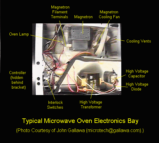
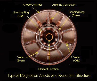
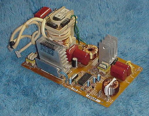