|
DEFINITIONS
Arbitration
When multiple devices need to use the Micro Channel bus at the same
time, these devices participate in arbitration. Every device that
can arbitrate for control of the bus is assigned a priority level, known
as an arbitration level, that is used to determine which device should
control the bus next. The arbitration level for each device is contained
in a software file, known as an adapter description file (ADF).
Note: Devices
that contend for control of the Micro Channel bus at the same time must
not have the same arbitration level. Occasionally, arbitration-level conflicts
occur between devices. When this occurs, you can use the system programs
to change the arbitration level of one of the conflicting devices.
Micro Channel architecture has a fairness
feature, which ensures that each device gets a turn to control the bus,
even if it has a low priority level. The fairness feature guarantees
that none of the devices are locked out of the bus and that each device
can gain control of the bus within a given amount of time. When you
configure your server, you can disable the fairness feature for a device
so that it controls the bus more than other devices. A device for
which fairness has been disabled can monopolize the bus. Disabling
the fairness feature for more than one device is risky. You could
cause some devices for which the fairness feature is enabled to be completely
locked out of the bus, including the microprocessor. Therefore, it
is best to leave the fairness feature enabled for all devices.
The central arbitration control
point is a location in the system master where contending devices
send their arbitration signals. It does not actually decide which
device should control the Micro Channel bus; the contending devices make
that determination among themselves, using the arbitration logic that is
programmed into the devices. However, it is the central arbitration
control point that actually grants control after the decision is made.
Burst Data Transfer
In non-Micro Channel servers, transferring each byte of
data is a two-step process. First, the microprocessor signals that
it is going to send a byte of data. Then it sends the byte and signals
that it is going to send the next byte. The microprocessor cannot
perform any other tasks while it is managing a data-transfer operation
in this way. Micro Channel architecture supports burst data transfers,
in which data is sent in multiple bytes without intervention by the microprocessor.
This improves system performance and allows faster data transfers between
devices.
In some servers, data from the hard disk is moved into
a buffer on the hard-disk controller before it is transferred across the
bus. (A buffer is a temporary storage space that compensates for
a difference in the rate of data flow when data is transferred from one
device to another.) Micro Channel architecture allows burst data
transfers from the hard disk to memory, without placing the data in a buffer
on the hard-disk controller.
Bus Parity Checking
Bus parity checking is a method of verifying that data
has not been changed during a data-transfer operation. Bus parity
checking uses an extra bit, known as a parity bit, that is sent with each
byte of data as it is transferred across the bus. The parity bit
is set to 1 or 0 so that each byte has an odd number of 1's (if the server
uses odd parity) or an even number of 1's (if the server uses even parity).
If the parity (odd or even) of the received byte does not match the parity
of the byte as it was sent, an error occurred during transmission and the
receiving device can request that the data be sent again.
Bus parity checking has become a common feature in most
servers. It is not 100% accurate, but it greatly reduces the chance
for errors. It is essential for most operations because of fast I/O
devices, complex I/O configurations, and large memory subsystems.
Channel Check Reporting and Error Logging
Errors can occur not only during data-transfer operations,
but also while data is stored in system memory. The contents of a
memory location can be changed accidentally, a memory module can be defective,
or other hardware failures can occur in the server.
Your server uses channel-check reporting to detect hardware
errors and error logging to record the errors. These records can
be used to diagnose and correct problems in the server.
The channel-check reporting facility automatically locates
random and intermittent errors while your server is operating. Information
about any failing component is saved in the error log so that you can identify
and replace the failing component.
Direct memory access (DMA)
Direct memory access (DMA) is a method of transferring
data between system memory and I/O devices without requiring intervention
by the microprocessor. DMA is more efficient than programmed I/O,
in which the microprocessor reads the data from the sending device and
then writes it to the receiving device. In DMA data transfers, data
can bypass the system microprocessor as it moves between system memory
and I/O devices. DMA improves server performance because the microprocessor
does not have to interrupt its processing activities to manage data transfers.
The DMA controller
is integrated into the processor board and manages all DMA data transfers.
Transferring data between system memory and an I/O device requires two
steps. Data goes from the sending device to the DMA controller and
then to the receiving device. The microprocessor gives the DMA controller
the location, destination, and amount of data that is to be transferred.
Then the DMA controller transfers the data, allowing the microprocessor
to continue with other processing tasks.
When a device needs to use the Micro Channel bus to send
or receive data, it competes with all the other devices that are trying
to gain control of the bus. This process is known as arbitration.
The DMA controller does not arbitrate for control of the bus; instead,
the I/O device that is sending or receiving data (the DMA slave) participates
in arbitration. It is the DMA controller, however, that takes control
of the bus when the central arbitration control point grants the DMA slave's
request.
Data bus parity
support provides for the verification of correct data as
it is transferred between the processor and memory and over the Micro Channel.
All data moved between individual components on the Processor Complex use
this feature (processor, memory controller DMA, Micro Channel controller)
Dual Path Memory
Allows both the processor and busmasters to access memory concurrently
though two paths.
Dual Bus Your server has a
dual bus, meaning that it has one data bus from the microprocessor to the
memory controller and another data bus from the Micro Channel devices to
the memory controller. This allows the microprocessor to read from
and write to system memory while a bus master is controlling the Micro
Channel bus.
The following list summarizes dual-bus operation:
o When the microprocessor is reading
from or writing to its internal cache or to the optional 256KB cache, the
bus master that is controlling the Micro Channel bus has exclusive access
to system memory.
o The microprocessor and the bus
master that is controlling the Micro Channel bus can use the system memory
at the same time, provided that they do not try to use the same memory
locations.
o When a bus master is reading
from or writing to an I/O device or an adapter in a Micro Channel expansion
slot, the microprocessor has exclusive access to system memory.
In servers that do not have a dual bus, the microprocessor
is the default master, which means that it has to wait until no other masters
are controlling the Micro Channel bus before it can have access to system
memory.
ECC- memory
controller which will automatically correct any single bit errors on the
fly (98% of memory errors are single bit); all 2 bit errors are found which
halt system; some 3 and 4 bit errors are found which halt system; single
bit errors are logged with optional software (NetFinity?) and multiple
bit errors are logged in NVRAM.
Enhanced
Dual Path Memory. Although Base 1 allows both the
processor and busmasters to access memory concurrently through two paths,
the Base 3 and 4 has buffers at both paths to provide better performance.
Also the buffer on the adapter side (I/O buffer) uses packet data transfers
for writes. This means 16 Bytes are collected and this packet is written
in one cycle to memory as opposed to writing for every 4 bytes received
(as with unbuffered systems).
Vital
Product Data Allows software (LAN Network Manager,
LAN Mgmt Utilities/2) to obtain a unique serial number (identifier) on
the processor complex which is in ROM (like Base 3). Also provides unique
ID (model/submodel), type/model/ serial number, manufacturing ID, planar
FRU number, and planar part number.
This system provides a means of storing and retrieving vital product
data (VPD). Vital-product data contains product-specific information that
describes various adapters and components within a system. This information
can be used in inventory and asset management.
In contrast to system configuration information, which is related to
resource allocation, vital-product data contains information related to
the physical characteristics, such as part number, engineering level, and
product name. For example, the vital-product data for the Server
95 system consists of the model and submodel bytes, the system type number,
the system serial number. The vital-product data for the system board
includes the system board serial number, a
replaceable-unit part number, and the manufacturing location.
The vital-product data for the processor complex includes the replaceable-unit
part number, a unique part identifier, and the manufacturer ID.
The VPD information for the system, system board, and any installed
options that also provide vital-product data can be read using BIOS calls
or operating-system utilities (if they are provided). For more information,
refer to Interrupt 15H, Vital Product Data System Service ((AH)=D2H) in
the IBM Personal System/2 and Personal Computer BIOS Interface Technical
Reference.
Kick-Butt
IBM 32 bit MCA busmasters that support 40 MB/sec streaming:
+Token-Ring LANStreamer MC 32
+Auto LANStreamer MC 32
+Dual LANStreamer MC 32
+EtherStreamer MC 32, Dual EtherStreamer MC 32
+SCSI-2 Fast/Wide Adapter/A
+SCSI-2 RAID Controller (in 95 A), SCSI-2 F/W Strm RAID Adapter/A
+All FDDI Micro Channel adapters
+3515 Adapter/A (actually supports 80 MB/sec if bus supports it)
+3514 Array Adapter (for external 3514 RAID 5 Array)
+ARTIC960 Co-processor Adapter (actually supports 80 MB/sec)
+TURBOWAYS 100 ATM Adapter
+Ethernet Quad PeerMaster Server Adapters (80 MB/sec)
Masters
A master is a device that can own the Micro Channel bus.
When a master owns the bus, it can send data to or receive data from a
slave (a device, an adapter, or system memory) without interrupting the
microprocessor. There are three types of masters: the system
master, bus masters, and the DMA controller.
System Master
The system master assigns system resources, manages the
system configuration, issues the commands of the primary operating system,
and can grant control of the Micro Channel bus to a bus master.
Bus Master
Your server supports up to 15 bus masters. Bus masters
take control of the Micro Channel bus and transfer data directly to and
from I/O devices and memory without requiring intervention by the system
microprocessor or DMA controller.
A bus master can have its own microprocessor, instruction
cache, and memory. By taking over some of the work of the system
microprocessor, bus masters create a multiprocessing environment and increase
overall system performance.
DMA Controller
The DMA controller manages data transfers between DMA
slaves and memory slaves. This type of transfer is often called a
third-party DMA operation. See Direct Memory Access Controller and
Direct Memory Access for more information.
Slaves
A slave is a device that is selected by a controlling
master as either the source or the target for a transfer. A slave
can also begin a service request, such as an interrupt. There are
three types of slaves: memory, I/O, and DMA.
Memory Slave
A memory slave is a device that provides a block of system
memory. Memory slaves respond to read and write operations by placing
the requested data on the Micro Channel bus or by writing data from the
bus to random access memory (RAM). A memory slave can be selected
by any of the three types of Micro Channel masters.
I/O Slave
An I/O slave is a device that communicates with or controls a separate
piece of equipment, such as a printer. An I/O slave can be selected
by the system master or by a bus master.
DMA Slave
A DMA slave is the only type of slave that can initiate arbitration.
DMA slaves require the DMA controller to manage data transfers. A
DMA slave can be selected by the DMA controller or by a bus master.
Streaming
data transfer.
The streaming-data procedure allows high-speed transfer
of data between bus masters and slaves. This procedure supports high-speed
transfers of large blocks of data for devices such as hard disk drives
and network adapters.
The streaming-data procedure transfers blocks of sequentially
stored data. In basic data-transfer operations, a target address
is assigned for every byte of data that is transferred. The streaming-data
procedure assigns a target address only to the first byte of data, and
the rest of the data in the block follows in sequence and is assigned to
sequential addresses. A streaming-data transfer operation takes 100
nanoseconds to send 4 bytes of data. This is a data-transfer rate
of 40 million bytes per second, which is twice as fast as basic data-transfer
operations.
The Micro Channel bus has 32 data lines and 32 address
lines. During streaming-data transfer operations, the 32 address
lines are used only at the beginning of a transfer cycle. Then they
remain idle for the rest of the cycle. The multiplexed streaming-data procedure
uses the address bus as another 32-bit data bus, allowing data to be transferred
64 bits at a time.
Subsystem
Control Block provides for the enhanced transfer of command,
data, and status information between busmasters (and between busmasters
and the system processor) to give increased performance. Capabilities such
as command chaining, data chaining, and block data moves frees the processor
from waiting for command completion before issuing the next command and
frees the processor for other tasks while a busmaster operates in parallel.
Adapters and device drivers must support this feature (many do today).
Synchronous
Channel Check support provides for the signaling of errors
synchronously with the transfer in progress. Adapters and device drivers
must be designed to support this feature (none do today).
.SynchroStream
controller which uses IBM's most advanced technology packaging
to integrate 5 major chips (memory, I/O, DMA controllers, FIFO buffers,
ECC logic) into one chip. This technology allows the high-speed interconnects
and large streaming pipes that form the SynchroStream engine to provide
state-of-the-art performance. The SynchroSteam controller synchronizes
data traveling between major subsystems and allows it to stream in parallel,
at full bandwidth, to each subsystem concurrently.
At the heart of the computer, data is moving continually between processor,
cache, main memory and the Micro Channel. Typically there is a single path
to memory, so fast devices like processors have to wait for much slower
I/O devices, slowing down the performance of the entire system to the speed
of the slowest device. The IBM SynchroStream controller was designed to
overcome this problem. It synchronizes the operation of fast and slow devices
and streams data to these devices to ensure all devices work at their data
at their optimum levels of performance.
Synchrostream is an intelligent device in that it predicts
what data the devices will need and loads it from memory before it is requested.
When the device wants the data, it is presented to it from the IBM SynchroStream
controller and the device can continue working immediately, as it does
not have to wait for the data to be collected from memory. When devices
are moving data into memory, the IBM SynchroStream controller holds the
data, and writes it to memory when it is most efficient to do so. Since
devices are not moving data to and from memory directly, but to the SynchroStream
controller, each device has its own logical path to memory. Devices do
not have to wait for other slower devices.
The SynchroStream engine operates by using a spinning
valve that continuously forms different connections between pipes. Once
a connection is made, data is streamed to the Micro Channel or processor
at the highest possible rates. Parallel paths allow data to stream to multiple
sources at the same time. The pipes even continue to stream after the connection
is changed. Data is always streaming to the Micro Channel and processor,
allowing them to operate at full bandwidth.
IBM used the latest in chip design technology to integrate
all SynchroStream functions on a single chip, improving performance dramatically
by not having to move data between chips. The IBM SynchroStream controller
uses a single RISC-like chip architecture to move data fast and efficiently
between memory and requesting devices, as shown in Figure 8.
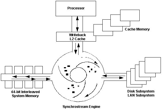
Figure 8. SynchroStream Technology
The IBM SynchroStream controller is located on the Pentium
processor complexes, featured in the Server 95 and Server 95 Array systems.
The implementation on the processor complex means that current PS/2 Server
95 and PS/2 Model 90 users can easily upgrade their machines to have IBM
SynchroStream controller functions.
Key advantages of the SynchroStream technology:
· Fast single chip implementation
Competitive designs are multi-chip and have the performance overhead
of moving information between chips. SynchroStream technology provides
a Zero Wait State Pentium implementation.
· Intelligence
IBM SynchroStream is intelligent in that it predictively loads data
from memory so that requesting devices are not kept waiting. In addition,
writes to memory are stored within the IBM SynchroStream controller and
written to memory to optimize memory utilization.
· RISC-like architecture
Pipelines are used to move data in a fast, efficient manner between
memory and the requesting device.
· Stream data to Micro Channel devices
SynchroStream can stream data to Micro Channel devices at 40MBps.
· Upgradable system implementation
Competitive system designs do not have the unique Upgradable Processor
Complex design so you cannot upgrade to SynchroStream-like functions from
earlier models.
9595
Main Page
|