Future Domain
@60E9.adf- IBM
PS/2 SCSI-2 or FD MCS-600/700 with 18C50 chipset
@6127.adf
Future Domain MCS-700 / MCS-600 with TMC-1800 chipset
@5F77.adf
Future Domain MCS-350
IBM
SCSI-2 Adapter/A Option Disk v1.00 For IBM/FD SCSI-2
powrscsi.exe
PowerSCSI
powscsi4.exe
PowerSCSI4
MCS-600/700 or IBM SCSI-2
Install
MCS-600/77/SCSI-2 Under W95
SCSI-2 on IML System
Lacuna Convenience Partition
FD and IBM Card Differences
FD/SCSI-2 and P70 ESDI
Running with the Devil (FD without
ROM)
MCS-600 and the DB25
Drive Shows
up as "Direct Access" (Use FDDSU.EXE)
MCS-600/700
TMC-1800 ADF Sections
MCS-600/700 or IBM SCSI-2
(18C50 chipset) ADF Section
MCS-350
MCS-350 ADF
Sections
MCS-200
The SCSI-2 Adapter /A was OEM'd by Future Domain, based
on the MCS-700 (18C50 VLSI chip). MCS-700 and MCS-600 use the same chipset,
but the MCS-600 has the Apple DB25 external port.
David Beem (HAL) pipes up with:
> What can the 18C50 do, that 1800 can not?
It may have been more on the chipset the controller
board had. Of the
MCA boards, MCS-600 = TMC-1800 vs. MCS-700 = TMC-18C50. The MCS-700
had the improvement of a jumper-selectable termination instead of removable
resistor packs. The external SCSI connection was a high-density DB-50 instead
of the 'Apple' DB-25 connection of the MCS-600. Shrouded internal SCSI
connector (helpful for the right orientation every time) & un-implemented
solder pads for jumper settings than could adjust some SCSI bus options
on the MCS-700 as well. The MCS-700 power connector was more conservatively
rated at 1.5 amps for the 12VDC and 5VDC pins, versus the 2 amp rating
on the MCS-600. Of course "C" in the chipset number means the power-saving
CMOS fabrication.
I have to see if these different chipsets return
different values for
the Future Domain BIOS call "Get SCSI Controller Information" INT 13h,
Function 18h. The book I have shows only values for the older FD chipsets.
There is another BIOS call that determines ANSI SCSI-1 or SCSI-2
compatibility. Of course the TMS-700 will have a much newer BIOS as
well. On the versions I have the boards are remarkably similiar despite
the 3 year difference in production. Tiny differences that add up on the
finer points of manufacture.
The FD design is PIO, not a busmaster. If you have a heavily
loaded system, or one with low powered CPU, you might look for a busmaster.
If you have a 486DX class system (or above) chances are the PIO will work
just fine, because the CPU has more than enough clock cycles to service
it.
PowerSCSI4
Use with MCS-700 and IBM SCSI-2 adapter. DOS/Win3.1
OPT_DISK.EXE
ADF files = Options Disk (v1.6)
NV2XX.EXE
Novell 286 drivers for v2.11-2.2 (1800/18C50/950 chipsets)
PWRSCSIN.EXE PowerSCSI
for Netware 386 (v1.2)
Specs
OS/2 v.3 Switches
MCS-600/700 or IBM
SCSI-2
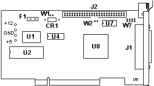
J1 External SCSI (HPDB50)
J2 Internal SCSI
F1 PTC Resistor
U1 40.0000 MHz osc
U2 BIOS
U4 NMS64X8AM20 |
U7 UC80989DWP
U8 18C50 (L1A7620)
W1 Term power
W2 Term enable
W? Pads for 8 pin header |
Jim Shorney pulls a few out
of the weeds and says:
Alternate part for U7 - REG5601U (on an IBM MCS700 71G3575).
18-line active terminator. PDF data sheet is here:
Alternate for U4 - CY7C185-20 - 8Kx8 static RAM. See here:
SCSI-2 Adapter/A Description
The SCSI-2 Adapter/A allows connection of internal and
external SCSI (max. up to 7) devices. The adapter uses ID 7. Devices can
use SCSI - ID 0 up to 6. (0 (Scanner/CD-ROM) priority /
6 = high priority (Hard Disk) devices) The total cable length should not
exceed 6-meters (18-ft). If any SCSI-Hard Disk is connected, then the total
max. cable length is 3 meters (9 feet).
Passive/Active SCSI Terminating
Passive terminating-resistors are normally fully functioning
if only internal or external
devices are connected. If there are internal and
external devices connected you MUST use ACTIVE -Terminating on both ends
of the SCSI - cables (internal/external), especially if there are fast
Hard-Disks or any other FAST SCSI-2 devices ( => 10MB/s ) connected.
TERMENA The
SCSI-2 Adapter/A has an integrated terminating-resistor (Jumper). This
jumper should only be removed if there are INTERNAL and also EXTERNAL SCSI
- devices connected.
TERMPWR This
jumper supplies the terminating-resistor voltage and should normally left
in place.
SCSI-2 on IML System
The 71G3575 will NOT support IML. Tthey will lay an IML
track, but can't access the IML partition. No end of frustration... Do
not try to use these in a 90 or 95 as an IML controller.
You can use the IBM SCSI-2 as a secondary controller where
they work fine. Hang a CD or a scanner off them. Nice to have a standard
SCSI port to use (no RS6K stuff). .
Lacuna Convenience
Partition
>Err ... Peter. All three of my 77s (9577-BTG) has a convenience
partition that was layed with the OEM'ed FD-MCS-700 that came standard.
Samething goes for my 76s (9576-BNB).
That's what I said. The system partition will not work
with the *original* Future Domain MCS-700 without the "IBM Support BIOS"
.... It works on the IDE-machines (with utilizing the IBM Int4B Abios extension
hooked to generic Bios Int13h -which is the boot / harddisk interrupt-
... attached to hardware IRQ 0Eh) and on the SCSI Models only with the
reworked IBM
controller BIOS. Reason why (to my opinion): the FD-controller
can utilize other hardware IRQs than only 0Eh (14).
My 9577-BTG has the IBM-version MCS-700 with the Rom BIOS 1.01 (I think)
and it has the "convenience partition" as well. I had the cached SCSI in
that machine as well - it also supports the partition, but is officially
not supported in the Lacunas.
MCS-600 and the
DB25
Al Savage confided to the
group:
Um, only the DB25 (early SCSI-1) used only one wire per
data line, with
a combined data ground (unless I'm wrong). All the other SCSI
wiring
uses a separate ground for every data line, which is why I sold off
all
my DB25 stuff and went C50 everywhere.
MCS-600/700
or IBM SCSI-2 under W95
Chances are, W9x won't get it right, and you might get a Future
Domain TMC-16xx series adapter installed. Which works, but not the best.
Manual install-
Control Panel>Add New Hardware>Future Domain (left hand
scroll box) > Future Domain MCS-600/700 (right hand scroll box).
Make sure the FD/SCSI-2 settings from under IBM's system
programs (refdisk or setup as you want to call it) are used. W95 knows
the choices available. Make sure the IO and IRQ are correct! If not, you
won't see a CD-Rom.
FD and IBM BIOS
Differences
Tim Clarke tossed
this out-
For the Future Domain MCS600/700 adapter ROMs -
a) Future Domain V3.nn = Future Domain and supports Int 13h via
Int 4Ch (SCSI-CAM). Does boot-drive scan from Id. 0-6. (Peter)...
but does not support IBM's ABIOS functions which use Int 4Bh, which is
the one that establishes / handles a "convenience / reference partition".
And which is the function that reports back the attached SCSI devices.
b) IBM V1.0n = Supports Int 13h via Int 4Bh (IBM SCSI). Does
boot-drive scan from Id. 6-0 and supports RefDisk Config and Diags.
(Peter)
1.00 seems to have limit at 4GB and -probably- with ATAPI
CD-ROMs. This is a "Lacuna"-specific problem when you have the harddisks
attached to the SCSI controller and an additional IDE CD-ROM on the systemboard
port.
I'd tried that on a machine with IBM Controller BIOS Rev.
1.0 and the system refused to even recognize the CD-ROM. I switched to
a 1.01 controller and -voilá- there it was. However: when I set
the CD-ROM to "Slave" it failed to work properly even with 1.01 on the
SCSI controller.
There seem to be dependencies within the Boot-BIOS part
of the IBM SCSI Bios on the FD-controller.
1.01 works fine with bigger HDs and CDs ... but dislikes CD-ROMs solely
attached to the IDE with a jumpering to "Slave". (Ed.
BUT even though it shows up under Set and View SCSI Devices, it does
NOT support IML! You cannot use it as the IML drive controller on a T1-T3
90 or 95.)
Finally, Peter sez:
The FD MCS-600/700 can be upgraded to an IBM SCSI-2 with
the IBM ROM. The two only differ by the DC-plug that the FD has and the
IBM lacks. The FD was originally designed as an "upgrade controller" to
add to an existing system which might not have a free DC-plug. The IBM
version was intended as "additional controller" (e.g. for tapes in a MCA
Server) or sole SCSI controller as in the Lacunas, which have enough DC-plugs
coming from the power supply. Just in case anyone wonders why IBM saved
the few pennies for the DC-plug
SCSI-2 and P70
ESDI Adventures
Jeff Hellige vents and sez:
I've got my P70 running again under OS/2 Warp Ver. 3 and regardless
of the slot it's placed in or the configuration, the MCS-700 seems to be
conflicting with the onboard ESDI controller in protected mode. POST
is reports the following error on bootup: 1047000
221 (ESDI Controller Wrap Failure)
If the SCSI board is left
in, OS/2 will run for a while and then start locking up, which makes sense
if the conflict is in Protected mode. DOS will run without errors.
The Reference diskette diagnostics configuration report shows the wrong
configuration with the board install and I've not attempted to go any further
with the SCSI board installed. With it removed the diagnostics goes
all the way through without errors, showing the
correct configuration.
The ROM version on the MCS-700
is 1.01. I've tried it in both slots as well as tried changing the
IRQ and such in the Reference disk setup. All of this had no effect
on the error.
1) reinstalled the MCS-700 with the IBM BIOS 1.01 still
installed. It continued to give the error and I ran diagnostics from the
Refdisk. The SCSI test gave an error of 0210000U.
2) I removed the BIOS and reinstalled. PowerSCSI4
would not install without a device hooked to the card so I connected an
external 1gig SCSI hard disk to it. Drivers installed fine under
both DOS and OS/2. No errors on boot and I'm able to access the drive
fine under both operating systems as well. It took 4-1/2 minutes
to copy 64meg of data from the internal DBA disk to the external SCSI disk.
I had tried to disable the BIOS in the system setup on
the Refdisk, but it didn't help. Removing the BIOS chip altogether
seems to have fixed it though. My only complaint is that it insists
on formatting the external hard disk with 32k sectors! I'll have
to play with that some more. Now the question is, what functionality
have I lost by removing the BIOS chip? Am I corrct to assume that
it won't be possible to boot off a SCSI disk in this
configuration?
FD w/o ROM
Tony roars with:
Setup a MCA flavor S/320 with one of the FD's (minus ROM)
running an Archive Viper tape drive. Nothing dramatic happened -
it just worked.
Nice to free up one of my scarcer v1.01 IBM ROMs so I can replace the
brain dead v1.0 in something else. BTW, autoconfig seems to want to allocate
a ROM address for the adapter by default. I just went in after autoconfig
ran and disabled the (nonexistant) ROM.
Tim Clarke
That's because the ROM actually has only 6KB mapped-in
and the controller chip has a 2KB "buffer" that is configured to be contiguous
with it, to make up the 8KB total "ROM" allocation. I'm not sure if the
"ROM Disabled" configuration means that the buffer is too, causing some
extra I/O overhead, or not.
ADF
File for MCS-600/700 board (TMC-1800 VLSI)
Version 1.1
AdapterID 06127h Future Domain SCSI Adapter
Adapter Memory Location
Memory location used for the BIOS ROM
<Segment CA00>,
Segment CE00, Segment DE00, Segment C800
Adapter I/O Location
I/O location the adapter will use
0140, <0150>,
0160, 0170
Select Interrupt Line
Interrupt used by the SCSI controller
<Int 5>, Int
10, Int 11, Int 12 (Mouse), Int 14 (Fixed Disk), Int 15 (Rsrvd), Int 3
(Serial Alternate), Int Disabled
ADF File
for MCS-700 /IBM MC SCSI-2 adapter (18C50
VLSI)
60E9 IBM PS/2 SCSI-2 Adapter/A or MCS-600/700
Adapter ROM BIOS Address
Memory address used for the ROM BIOS. In general,
the BIOS must be enabled to support fixed or removable SCSI disk drives.
If you are using the PowerSCSI software, and if the only SCSI devicesattached
to this controller are tapes, CD-ROM drives or non-direct access devices,
the BIOS may be disabled to speed system startup
<Segment CA00>,
CE00, DE00, C800, Disabled
Adapter I/O Port Address
I/O port addresses the adapter will
use
<0140h>, 0150h,
0160h, 0170h
SCSI Adapter Address (ID)
SCSI ID of the adapter is fixed and
cannot be changed
<7>
Select Interrupt Line
Interrupt used by the SCSI controller
<IRQ 5>, IRQ
10, IRQ 11, IRQ 15, IRQ 3, IRQ 14, Disabled
Direct Access
Fix?
>I've tried to add a 2GB 0664 drive as ID4 to my system. The added
drive at ID 4 is listed as "direct access" instead of "hard disk," and
no size is listed. When I attempt to low-level format, the list of available
drives does not include the drive at ID 4. Can someone please tell how
to revive the 0664 that responds as a "direct access" device???
The Magic Christian responds:
The procedure requires a Future Domain FD-600/700, the IBM OEM'ed version
of the same aka SCSI-2, or something else that can run the DOS utility
FDDSU.EXE that comes with 'Powerscsi4'
quote begin:
'The following procedure should read the firmware parameters from
a SCSI drive and then write those parameters back to the media. This will
normally restore a fixed disk to the factory default parameters. Not all
drives will support this procedure. Future Domain will not be responsible
for the results stemming from the use or misuse of this procedure.
1. Insert the Future Domain "SETUP" utility.
2. Type "SETUP" and press <RETURN>.
3. A screen will appear displaying the SCSI ID and LUN of the
drive.
4. A menu will appear as follows:
1. Format Unit
2. Edit Defect List
3. Surface Analysis
5. Press the <F5> function key to invoke the Custom Utility menu.
6. When you press <F5> a message will appear stating "you are about
to
enter the Custom Utility...", answer yes to continue.
7. A menu will appear as follows:
1. Format Unit
2. Edit Defect List
3. Surface Analysis
4. Sense Byte Editor
8. Choose option 4. Sense Byte Editor.
9. A menu appears as follows:
1. Mode Sense
2. Write sense data to a file
3. Read sense data from a file
4. Print current list
5. Edit current list
6. Set options
10. Choose option 6. Set options.
11. A window appears and asks if you want to change Mode Select byte
1. Answer no.
12. You are asked if you want to change Mode Sense byte 2. Answer yes.
13. Enter the hex value "BF" and press <RETURN>
14. The Sense Edit menu appears. Select option 1. Mode Sense.
15. Now select option 5. Edit current list.
16. A window will open up in the left side of the screen. These are
the
Page codes of the SCSI drive.
17. Press the <F7> function key. A message at the bottom of the
screen
should say "Sense Info sent successfully".
18. Press <ESC> twice to exit back to the main menu.
19. Choose option 1. Format Unit.
20. When asked "Permission to format", answer yes.
This should update the media with the parameters from the
firmware. The
drive must accept and finish the low-level format for the above procedure
to work correctly. Also, some drives do not support a low-level format.
When in doubt check with the drive manufacturer. If you have any questions,
please feel free to call Tech Support at (714) 253-0440, or fax at
(714)
253-0429.'
Specs
PS/2 SCSI-2 Adapter/A
| SCSI type |
SCSI-2 Fast |
| SCSI bus path / speed |
8 bit / 10 MB/sec |
| I/O bus path / speed |
32 bit / 16.6 MB/sec |
| RAID levels |
None (use software) |
| Tagged Command Queuing |
No |
| Processor |
None (PIO) |
| Channels |
One (internal/external) |
| Connectors |
One internal; one external |
| Devices supported |
7 devices per adapter |
| Cache std / max |
0 KB / 0 KB (8 KB buffer) |
OS/2 Switches
The following drivers support Future Domain and IBM SCSI host adapters:
FD8XX.ADD supports Future Domain and
IBM 8-bit SCSI adapters.
FD16-700.ADD supports FD 16-bit SCSI
adapters
BASEDEV= ---- FD8XX.ADD --------------------------------------
- FD16-700.ADD -| - /ET
-| Search SCSI devices for Logical Units
+- FD7000EX.ADD -+ - /FS
-| Enable fast synchronous data transfers
(TMC-1850 chipset ONLY)
+- /RD:n+ Maximum
device recovery time
-------------------------------------------|
+- /A:n
----------------------+ Adapter
number
|- /!DM ----------| Disable
DASD Manager
| +- :unitlist
+ List of unit identifiers
|- /!SM ---------| Disable
SCSI Manager
| +- :unitlist-+
List
of unit identifiers
+- /ET ----------|Search
for Logical Units
+- :unitlist + List
of unit identifiers
MCS-350
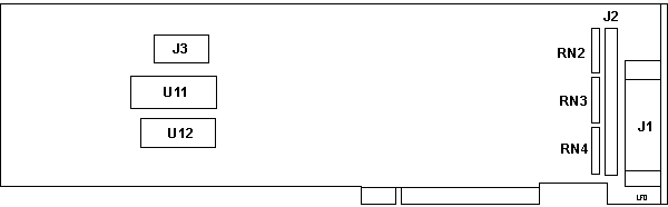
J1 DB25
J2 50 pin internal
J3 Drive Power |
RN2,3,4 RKL8B221/331/G
U11 FD Bios V1.0E BB
U12 UM6116-3 |
AdapterID 5F77 Future
Domain SCSI Adapter
Memory Location
Memory location used for the BIOS ROM
<"Segment CA00" (ca00-cbff)>,
C800 (c800-c9ff), CC00 (cc00-cdff), CE00 (ce00-cfff), D000 (d000-d1ff),
D200 (d200-d3ff), D400 (d400-d5ff), D600 (d600-d7ff), D800 (d800-d9ff),
DA00 (da00-dbff), DC00 (dc00-ddff), DE00 (de00-dfff)
DMA Arbitration Level
DMA channel the adapter will use to transfer data.
<"Level 6">,
7, 5, 0, 1, 3, 4
Select Interrupt Line
Interrupt used by the SCSI controller
<"Interrupt 5 (Reserved)">,
3 (Serial Alternate), 10 (Reserved), 11 (Reserved), 12 (Mouse), 14 (Fixed
Disk), 5 (Reserved)"
Use Front Panel Disk Busy Light
Whether the front panel light is to be used by the SCSI
devices to indicate that a SCSI device is busy. The same light is
also used by the internally installed hard drive. There is no conflict
if the same light is used by both devices.
<"Use Front
Panel Light">, Do Not Use Panel Light
Use MC BUS Wait (IBM Model 80)
Select the extended synchronous bus cycle is to be used
as the default fastest cycle on the transfer of DMA data to the SCSI device.
The Model 80 will not support full speed DMA writes via the uChannel bus,
so this option is required for high speed devices on the Model 80.
<"Use Wait
State (Model 80)">, Do Not Use Wait State
MCS-200
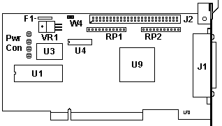
F1 Termpwr fuse
J1 DB25 SCSI
J2 50 pin header
RP1, RP2 Resistor Pack RKL 10S101G
U1 BIOS |
U3 40.0000 MHz Osc
U4 Toshiba TC5588J-20
U9 FD TMC-1800
VR1 Linear Tech. LT1086CT
W4 Termpwr Jumper |
External Port
The external port is the Apple DB25 style SCSI pinout.
Termpwr Fuse
The Termpwr fuse is a PTC Resistor which goes to high
resistance if too much current flows while providing Termination Power
to the SCSI devices. When the overload is removed, the PTC resistor cools
down and allows normal operation.
9595
Main Page
|