|
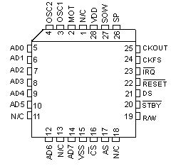
Wild Bill Walsh slings lead with: I found this on a Motorola MC146818AP...not exactly what you have, but maybe close enough to work. .Motorola MC146818AP or compatible This is a rectangular 24-pin DIP chip, usually in a socket. Compatible chips are made by several manufacturers including Hitachi (HD146818AP) and Samsung (KS82C6818A). The number on the chip should end in 6818. Although this chip is pin-compatible with the Dallas 1287/1287A, there is no built-in battery. This means that CMOS RAM can be cleared on this chip by just removing it from the socket for a few seconds and replacing it. To reduce chances of damage to the chip, it is preferable instead to
short
Here is a picture of the 6818 chip:
___________
Franc Zabkar wrote:
The hardware clock is maintained by an MC146818 compatible RTC which
is operated at a crystal frequency of 32.768 kHz. This crystal is
DOS and Windows maintain a separate software clock derived from the
Since the two crystals may drift from their nominal values, it is possible that the S/W and H/W clocks may not correspond. The frequency of the 14.31818 MHz crystal may sometimes be trimmed for better accuracy by adjusting a small variable capacitor located nearby. Another reason for the S/W clock lagging behind the H/W clock may be that IRQ0 is not being regularly serviced, despite it having the highest priority. Other devices may be demanding too much of the CPU's attention, thus causing some timer interrupts to be missed. Some people claim that buggy power management may also cause this. This little QBASIC program reads the time in hh:mm:ss format: PRINT "The H/W time is "; FOR I = 4 TO 0 STEP -2
PRINT
I have verified that writing directly to the H/W clock in CMOS RAM does
not affect the S/W clock until the next reboot. However, the TIME command
at the DOS prompt adjusts both the the H/W and S/W clocks
|
