|
A long time coming, but worth it.
Mounting Hardware
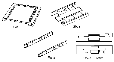
Drives come in a variety of heights. You can install half-high drives that are less than 41.3 mm (1.6 in.) high in any of the bays. Drives that are greater than 41.3 mm (1.6 in.) high (full-high) can be installed in bay C or bay D. Bays C and D can each hold two half-high drives or one full-high drive. Different types of hardware (slides, rails, and trays) are used to install a drive in a bay. The type and size of the drive, as well as where it is to be installed, determine what hardware you will need when installing it. Cover plates
(sometimes called bezels) cover the front of each installed drive. If you
install a drive that uses removable media (diskette, tape, optical disc,
or CD), you will need to change the cover plate.
Installing Floppy Drives Install the diskette drive in bay A or B: Note: The figures that accompany these steps show the installation occurring in bay A. These instructions also apply to bay B. a. If a flat cable is folded inside bay A, unfold it and route it along the back of the bays. b. Position the drive so the connector is facing the rear of the server. c. Align the drive with the guides on the bottom of the bay. d. Slide the drive into the bay until it stops.
3.5" Floppy Drive Slide 64F0156
Remove Rail Guide From Storage Tray Pull up on the tab (1) on the back of the tray and pull out the rails stored on the bottom of the tray. Storage Tray 84F8075
Insert Rail Guide
5.25" Drive Rail Dimensions 
I measured this from a single RAID bay.
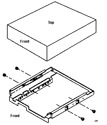
HD Mounting Tray 
85 P/N 85F0013
My 9595s are stamped 10G4769. NOTE: The drive may be installed
in the tray with the mounting screw flange pointed down (as pictured)
or pointed up. This is helpful if you have a mix of 1.6" and 1" drives
to install.
|
