85, 95, and 3511 PS
Power Supply Revisions
Max Amp and Power Draw
Checking Power Supply
Voltages
Quick
Op Panel Check
Primary
Power Supply Voltages
Drive
Connector Voltages
Reliability
High Quality
Side Cover Fan
Side Cover Fan Orientation
Case Airflow
Side Cover Fan Construction
Side Cover Fan Revisions
Side Cover Fan Troubleshooting
How Does The
Fan Look Installed? (Takes you to Jim Shorney's site)
Deriving 17vdc from the Power Connector
E-Clip for PS Knob Assembly
Air Deflector on
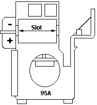
95A PSU
Opening 95A Power Supply
Security
Torx
Security
Phillips
Removing
AMP Planar Power Socket Retainer
95A Power
Supply Exposed!
Power Supply
AC Socket
Fan
Fuse
Blown Transformer
Power Supply
Revisions
The wattage is rounded up - for better look. Basically
you find the "old" 335Watts PSU (FRU 92F0051) in all 8595 machines and
later "small" Server 85 (those with 486SX and 8-bit planar SCSI). The 285Watt
(FRU 92F2637) has been installed on the earlier Server 85 only and on some
*very* few 8595-xGx, xHx and -xJx. (Ed.
My 9585-xNx has a 285W PS)
The 400W was introduced for the Server 95A. The 9595-xLx
and -xMx however use the 335W since they are souped up 8595 only. The bigger
PSU (FRU 92F0267) can be identified by the LED and test-button at the top
left corner, when looking at the installed PSU. The "bigger" Server 85
(486DX2 and F/W planar SCSI) have this one as well as the 3511 expansion
unit.
Maximum Current
and Power Draw
The system provides a separate power source for internal SCSI drives
through three 4-pin connectors on the power supply (see Power Supply Connectors).
The system board voltages are +5 V dc, +12 V dc, and -12 V dc. The
drive voltages are +5 V dc and +12 V dc.
The following are the maximum current and power considerations used
in designing the power supply and system board. The formulas used to determine
the power requirements and the voltage regulation tolerances for adapters
are in the Micro Channel architecture information in the IBM Personal System/2
Hardware Interface Technical Reference--Architectures.
Component Maximum Current
|-------------------------------------------------------------|
|
| MAXIMUM CURRENT
|
|
|-----------------------------|
|
| -12 V | +12 V |
|
| SYSTEM COMPONENT
| DC | DC |
+5 V DC |
|-------------------------------+---------+---------+---------|
| System board
| 1.0 A | 1.6 A | 28.0 A |
|-------------------------------+---------+---------+---------|
| Internal floppies (per drive} | None | 300
mA | 600 mA |
|-------------------------------+---------+---------+---------|
| Keyboard port
| None | None | 300 mA |
|-------------------------------+---------+---------+---------|
| Auxiliary device port
| None | None | 300 mA |
|-------------------------------+---------+---------+---------|
| Internal SCSI drives*** |
None | 7.0 A | 8.0 A |
|-------------------------------+---------+---------+---------|
| MCA adapters (per slot) |
40 mA | 175 mA | 2.8 A |
|-------------------------------------------------------------|
| *** Total for all internal drives
|
+-------------------------------------------------------------+
Note Some adapters and drives draw
more current than the recommended limits. These adapters and drives can
be installed in the system; however, the power supply will shut down if
the total power used exceeds the maximum available power.
Checking Power
Supply Voltages PS/2 - Server 85, Model
95 and 3511
Some power supplies have a built-in test switch and LED
on the side of the power supply (there is no need to check voltages). On
those power supplies, disconnect the power supply from the system board,
and remove all cables except the power cord. Power-on the power supply
and push the test button. If the LED lights up, and the power supply fan
runs, the power supply is OK.
On all other power supplies, short pin 1 to pin 2 and
read the voltages on the other pins. If the voltages are correct, and the
power supply fan runs, the power supply is OK.
Quickee
Op Panel Check
 Thanks
to Rick Starich for getting me
to do this! Thanks
to Rick Starich for getting me
to do this!
Pull Op Panel out front of system. Leave PSU connected
and plugged in. Short pins 3-6 OR 5-4
and system should power up if the Op Panel board and cable are good. Do
not short 5-6 or 3-4, as nothing will happen.
Primary Power
Supply Voltages
If the voltages are correct and the power supply fan
runs, the power supply is OK.
Power
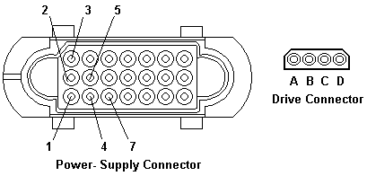
Supply Connector Voltages
| -Lead Pin |
+Lead Pin |
Vdc Minimum |
Vdc Maximum |
5
5
5
5 |
9
3
4
7 |
-3.7
+3.7
+9.0
-9.0 |
-6.2
+ 6.2
+15.0
-15.0 |
Note: -5vdc on pin 9 is undocumented.
Didn't notice a -5v on my 95A PS
Note: Black lead of the DMM/VOM
on pin 5, red lead to the +Lead Pin.
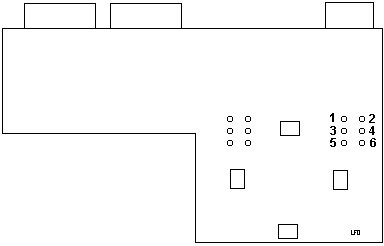
95A Planar Power Socket Pinout
Top row is all +5v (Red). The middle row is all Gnd (Black).
The bottom row is, from L-R, On/Off (Brown), +12v (Blue), -12v (Yellow),
+5v (Red), Gnd (Black), PG (White), Gnd (Black)
Drive
Connector Voltages
| -Lead Pin |
+Lead Pin |
Vdc Minimum |
Vdc Maximum |
B
B |
D
A |
+ 3.7
+ 9.0 |
+ 6.2
+15.0 |
|
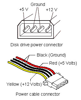
Wire Colors for Disk Drive Power Connector
IBM used Yellow-Black-Black-Yellow.
If the power supply shuts down, or appears to fail at power-on, you
might have one of the following problems:
Too many devices are set to start instantly.
Check Motor-Start Jumper.
There are too many large-capacity devices
installed.
Or the Remote Maintenance Service Jumper
is not correct.
But to answer your question: the Mod. 95
PSU is not known for any particular failure. There was a series of downlevel
"Delta /US" made 400 Watt PSUs, which failed after a short time - but these
have blown themselves to hell already and none of them has seen the year
1992.
The 95-PSU is rather complex inside. The main functions
are distributed among a number of smaller boards and tracking down failures
isn't easy - except you have blown and burned parts. In most cases however
the failing components are not that obvious to find.
The most common failure is the "no turning on" failure
with the short clicking noise and the high-pitch whistle afterwards. I
don't know which component causes this - and how to repair it.
Malfunctions that the PSU works for some time and then
-by no obvious reason- switches off (thermal problem) are only reported
for *extremely* dirty PSUs, mainly accompanied by blocked fans. After some
time running the internal protection circuit causes a "thermal shutdown"
due to overheating. This could be fixed in most cases by cleaning the thing
and replacing the fan.
The commonly known problem with overheating and burning
the stand-by part of the PSU are not reported for the 95 PSU ... it is
no Magnetek / Italy made PSU ... :-)
High Quality
From Peter
Hi Jim !
>The thing is built like the proverbial brick outhouse.
A guy who (professionally) repairs switched power supplies
looked into a dead 95 PSU and was surprised as well. "How old did you say
are the Mod. 95s ?"
He was confused about the fact that an almost 10 year
old machine had a PSU with power factor correction ... which might become
standard "by law" next year or in 2002 for the common lemming PCs.
If you have an AC wattmeter - plug in the PSU, shorten
the "powerswitch pin" and test out the idle wattage it takes. It is much
lesser than the average wattage taken from a 145W chop-suey PSU from China
or elsewhere. And the 95 PSU has 380 - 400W output power ....
Also a nice test is the "VDE 0100 Isolation Test" and
the test for parasitic currents over the input noise suppression filters.
The 95 supply is also a class of its own here. IBM wasn't cheap-skating
on the PSUs.
Even the notorious Magnetek "Made in Italy" power supplies
for the 35/56/76 are pretty good on their technical data and performance
... apart from the unlucky tendency to fry themselves to an early death.
The concept was good - the manufacturer wasn't. (Or the quality control).
Side
Cover Fan
Part of the following was redone
based on info found by Ross Barker (Ross pulled up anchor- he's on the
high seas again)
Side
Cover Fan Orientation
This is a swirling debate... For now, I'd like to point out the
difference between the 95 and 95A plastic end bracket for the fan. The
95A bracket has a slot and a beefier catch.
Airflow
The fan serves one purpose in either mounting orientation,
that of pulling air IN through the grilles at the top front of the 95,
then THROUGH the adapters, then DOWN the side wall.
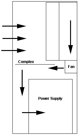
Open to interpretation... The significant points- air is pulled through
the top grilles, sucked through the adapter cards, down the side wall through
the side wall fan.
Air is sucked over the top of the PSU, past the complex,
over the memory, then into the PSU where it is blown out through the exhaust.
Though looking at a PSU shows the memory has a blank surface in front of
it, probably to force airflow past it.
Side Fan
Construction
From Peter-
But please do not forget that this thing is not just a
simple "motor". It is an electronically regulated, brushless DC-motor.
The electronics sits under the end facing to the rear - you can see the
printboard and some of the coils. The electronic itself consists out of
some resistors and condensors, ICs, a hall-generator for measuring the
rotational speed and so on.
Unlike to "real motors" the resistance does not change
when you turn the fan ... normal DC-motors act as generators once driven.
This thing doesn't.
However: 137 Ohms would give a current of about 125 mA
- still below the specs.
Side Fan
Revisions
64F4470, EC C31557, mfd. 042391 137 ohms
64F4470, EC C32546, mfd. 121391 1.31K Ohm
Hosiden HMK 3404-01-092, DC 17v. 0.185A
64F4470, EC C32546, mfd. 031892 1.32K Ohm
Hosiden (flower symbol?) W, HMK 3404-01-092, DC 17v. 0.185A
95A Side cooling fan fan
ASM P/N 61G3813, mfd. 101993 1.32K Ohm
Hosiden (flower symbol?) J, HMK 3404-01-092, DC 17v. 0.185A
Possibly this means any fan made on or after 121391 will be a 1.3K ohm
model.
Side
Fan Troubleshooting
If the access cover fan does not work, check:
Check the spring contacts on the fan bracket to see that
they stick out far enough. Over time, with repeated removal and installation
of the side cover, the contacts will be pushed back into their guides.
Carefully pull them out again. Make sure the free end of the spring enters
the recess when not under pressure (that way it's lined up when you are
using BOTH hands to install the side cover...)
Power to fan: 17 V dc (+/- 1.4 V dc) at the two fan cable
pins on the base.
If voltage is correct, check for 1.3K ohms (+/- 10%) between fan terminals
(Ed. I have an older fan that has 137
ohms. Runs fine.)
If resistance is incorrect, replace the fan. If resistance
is correct, check spring clip connectors. (If good, there isn't a fan problem).
If voltage is incorrect, unplug fan cable from connector
J28 on planar and check cable assembly for continuity. If cable has continuity,
replace the system board. If the cable does not have continuity, replace
it.
Deriving 17vdc
from the power connector
OK, you have a 9595-3Px, fully loaded with RAID drives and memory.
BUT you notice strange erratic performance after a few minutes. After checking,
you notice (to your horror) that you have NO voltage (or not enough) from
J28.
Just trot down to Best Buy and pick up the dual serial/parallel
planar for $49.99 and pop it in? Or will you whip out your trusty 25W soldering
iron and take charge of your own destiny? If you are of the adventurous
type, read on!
>So if J28 does not have 17vdc present, can you come off pin 9 and pin
4?
Yes - sure. The Pin 9 is the unused -5V source (PS/2 don't
use that - it is not even mentioned in the HMM). You pick the voltage preferably
at the underside ... but ... if there is no +17V at J28 ... then there
is something basically wrong. The +12V should be present anyways (the HD-motors
run on it) ... if the -5V is missing then the PSU had "a bad day". Or the
line is cracked on the board somewhere. This should be easy to trace down.
>That was my intent- how to derive an alternate source of 17vdc from
the planar power socket...
Alternatively: pin 7 of the PSU-connector deliveres -12V,
pin 3 +5V ... both add to +17V as well. Only need to watch the polarity.
(Ed. Verify the polarity with a voltmeter/DMM.
Do not assume anything with a 9595 dual serial/parallel planar. One bzzt!
and you may burn something else on the planar. The Power Supply will be
fine though...)
E-Clip
This came out of the blue one day. How were all these PSUs missing
E-Clips on the PSU knob?
How it happens- (from Charles)
The ijits that used these computers before don't realize
that it's the little e-clip that actually stops the screw knob from turning
further.
If you crank on it hard enough, you WILL deform the clip,
dislodging it from the shaft, USUALLY the next time the PSU is unseated.
It starts with a very hard counterclockwise turn, and then you notice that
that nothing is moving as you turn the knob. Then when you pull -- pop!
The e-clip finally gives way.
Charles Lasitter
Does anyone know the correct E-clip size for the spring-loaded
screw shaft that we all know and love in the '95? I've had about
a dozen too many of them come flying apart and of course one of the E-clips
takes its own separate orbit.
My nuts 'n bolts reply
The .670 is, as stated, the recess width which the e-clip
has to fit. .553 is the outside diameter of the e-clip. So an e-clip with
an outside dimension of .553 (or a little less, hell, .450 should do) all
the way up to .650 should do.
The thread outer diameter is roughly .310". So the outside shaft
diameter will probably be a little larger, maybe .318 (standard fractional
dimension, IIRC)
The diameter of the part where the eclip rides should
be .208 plus/minus maybe .003". Thickness of the e-clip is .025".
Bob Watts
You can go to NAPA and ask for part number: 1311. They
are 32 ¢ each. I know they work because I installed them on
my 8595 PSU. Problem taken care of.
From the god Emperor of Microchannel
Went to NAPA. Got a few 1311s. They are tight, Bob.
On a lark, I went to Ace Hardware. Ambled over to the
fastener center. Whipped open the Hillman External Retaining Rings box.
Pulled out a 5/16th Retaining Ring, 08236-00379 for a whopping 20 cents
each.
They aren't as loose as the IBM e-clip, but you can turn
then with your fingers (the NAPA ones wouldn't)
95 PS vs 95A PS
Just a little factoid- the 8595/9595 power supplies do not fully
enclose the well that the PS knob's screw is in. This makes it possible
for an e-clip to pop off the shaft and fall into the PS. On the 95A 400W
power supplies, that well is solid all around the threaded end of the knob's
shaft.
95A Air Deflector
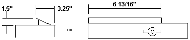
It starts on the left front corner of the PSU. 17.2cm/6 13/16ths" wide.
The air baffle extends towards the complex 8.7cm/3 1/4" inch from the outer
edge of the PSU. The air baffle has a maximum height of 3cm/1.5".
95A PS
Delta model SMP-400BP?
I opened up my 95A 400W power supply. I do NOT
advise anyone to attempt to fix or modify the power supply. I take NO
responsibility for what you do! You are doing this on your own!
This page is ONLY
to expose you to the quality construction used on the 85/95 series systems!
I have left many details out, because I'd rather not have people opening
these power supplies. They have pretty big capacitors in there. Seen bigger,
but these will hold a sufficient charge to ruin your day.
For entertainment only!
In no way do I suggest that you try this! I am waiting on safety tips for
the proper de-energizing of the circuitry for power supplies that have
been used recently. I used a power supply that hadn't been powered up for
over six months.
Assume all heatsinks are live if this power
supply was plugged in!
Security Torx
I went to Menards (no foolin!) and they just got in some
Truecraft model #6232 32 Piece Bit & Socket Magnetic Ratcheting Driver
Sets (about $20). It has tamper proof T10-T40 Torx bits.
The bits and case are Taiwanese (I'll buy from OUR
china any day!) and the ratchet and sockets are US. The bits are heat treated
S2 steel (good stuff). You will need the T-15 bit.
Security Phillips
To take off the inner side panel, you WILL need a security
Phillips. The 95A PS uses a stamped metal "well" to fully surround the
PS knob's threaded end. This well is fastened to the top of the case, as
well as to the side panel by the security phillips.
I made my "security phillips" screwdriver with a cheap
old phillips. Threw it into a vise and hacksawed two slots at right angles
to the edges. It has four seperate points sticking up around the center
now. I would get a real security phillips if I was doing this alot. It
worked but I would not want to really torque on it.
Removing the PS
Knob
Push the knob in so the e-clip on the inner side is accessible.
Use needlenose pliers or a standard screwdriver to remove it.
Removing the
Planar Power Socket
If you want to unmount the AMP planar power socket, you
will need a standard screwdriver. The retaining collar has two pairs of
hooks on each side of the power socket. With the PS on the ps knob side,
look under the metal angle that the PS is mounted on.
See the hooks holding on the bottom of the socket? While
pulling up on the collar, pry the hooks away from the socket, one end
on one side, then the other end. Move to the other side and work off the
hooks again one at a time.
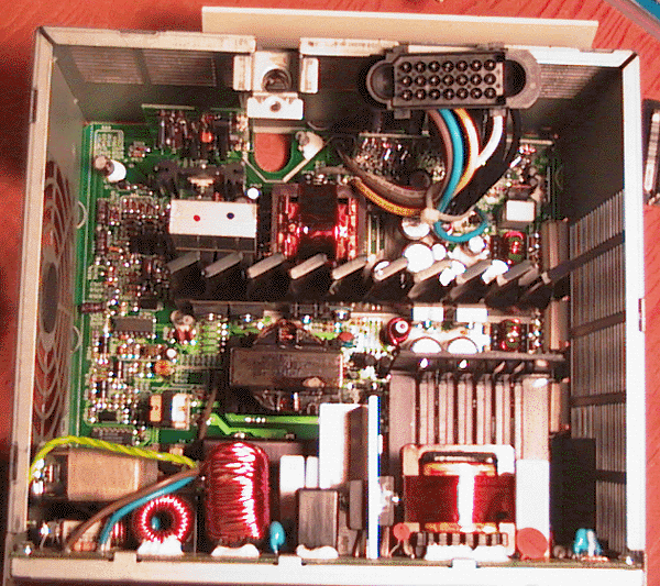
Oh My God! 95A
Power Supply Exposed!
This is NOT a clone power supply! The main heatsink is
3" high, 3/16th" thick and 7" long! The conductors coming off the main
circuitboard are 14AWG, 600v, 105 degree rated. For those not techno-savvy,
that means you could safely run 115v/15A on these conductors! The 105 rating
is WAY above some common power supplies I've looked at. The fan is removed
in this inage. Look HERE
95A Power Supply
AC Socket
It has an EMI filter, rated 115/250v,
10A at 50/60Hz, 40 degrees C.
Fan
Wasn't able to get a model off it.
The fan is 4 11/16"H x 4 11/16"W x 1 1/2" deep 12v. I saw no temperature
sensing circuitry that I recognized on the mini-circuitboard that the fan
gets power from. Looking for a QUIETER fan.
Fuse
T8AH 250V. If this fuse blows, remove
the short circuit from the output. Though if this has blown, something
is wrong because the power supply should have shut down by itself!!! If
the fuse blows again after removing a shorted output, I recommend you take
a power supply to a real electronics repair tech.
Blown Transformer
Unfortunate victim is Frans
Huizing
One day, smoke came from the PSU
and it promptly shut itself down. I opened it up, (yes, I have the
proper tool) and found 3 pieces of ferrite loose in the supply: part
of the core of a transformer. One piece had lodged itself between what
looks like a small regulator board and the main circuit board where the
short caused some physical damage to an area that is not used. Yes,
the 8A fuse was blown. However, on the little circuit board on the right
top corner are , what looks like, 3 resistors. The middle one has been
fatally damaged.
Now I come to my questions: Where
can I find the schematic for this supply.(Delta, SMP-400BB, EC3 D30618)
And can you think of any reason other than a manufactoring flaw why that
xformer fell apart?
Dr Jim
Shorney replies
>Hey Jim, can this be cleaned up, a new transformer
installed, and a new resistor installed? I don't know of a source for schematics,
and I know that Delta will NOT just hand them out to a hardware hacker...
Jim sez
My advice: scrap it and send me
the fan. When you see catastrophic damage like that (melted and charred
parts, things blown off the circuit board), there is usually a fair amount
of other damage lurking in the shadows. You would end up throwing
more parts at the thing than what it is worth.
>Why the hell would a core fail like this?
Powered ferrite cores aren't a terribly mechanically
robust thing. Could have been dropped. Or it could have been cracked
by an intense high-frequency spike from a nearby (or direct) lightning
strike.
9595 Main
Page
|