|
9552 Power
Power Systems Checkout
Note: One or all of the batteries
can discharge if there is a short circuit in the system.
1. Replace the failing FRU if the power supply problem is caused by
a short circuit.
2. Determine if one (or all) of the batteries have become discharged.
Replace any discharged battery with its spare, if available.
How to test:
AC Adapter
Car Battery Adapter (700 only)
Battery Pack
Backup Battery
Standby Battery
Quick Charger
Voltage Converter (700, 700C)
Voltage Converter (720, 720C)
Checking the AC Adapter:
If the Power-On indicator does not turn-on, check the
power cord of the AC adapter for correct continuity and installation.
1. If any noise can be heard from AC adapter when it is plugged into
ac power outlet, replace AC adapter. If no noise can be heard from AC adapter,
go to step 3.
2. If a noise is still heard from new AC adapter, suspect the computer.
Replace AC adapter with the original one, then go to the next step. If
no noise is heard from new AC adapter, the original AC adapter is defective.
3. Unplug the AC adapter cable from the computer and measure the output
voltage at the plug of the AC adapter cable.
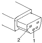
|
Pin
|
Voltage (V dc)
|
|
1
|
+19.0 to +21.0
|
|
2
|
Ground
|
o If the voltage is not correct, go to
the next step.
4. Unplug the AC adapter cable from the ac power outlet and wait for
a few minutes.
5. Plug the AC adapter cable into the ac power outlet.
6. Measure the output voltage of the AC adapter.
o If the voltage is still not correct,
replace the AC adapter.
o If voltage is correct, plug AC adapter
cable into computer and try the failing operation again.
o If the problem goes away, suspect the
continuity or installation of the AC adapter cable.
o If the problem is not corrected, replace
the voltage converter.
AC Adapter (25W or 40W)
Checking
the Car Battery Adapter (700 only):
If the output voltage from the cigarette lighter socket
of the car is less than 10.5 V dc, the power-on indicator on the car battery
adapter blinks and a noise can be heard continuously.
1. Unplug the car battery adapter cable from the connector, if connected.
2. Plug the car battery adapter into the cigarette lighter socket.
Note:
If the adapter is already plugged in, be sure to unplug the adapter from
the cigarette lighter socket, then plug it back in.
3. Measure the output voltage of the car battery adapter cable.
|
Pin
|
Voltage (V dc)
|
|
1
|
+19.0 to +21.0
|
|
2
|
Ground
|
o If the voltage is correct and the power-on
indicator on the car battery adapter is on all the
time, the car battery is working correctly. Replace the voltage converter.
If the problem is
not resolved when the voltage converter is replaced, go to Checking
the Voltage Converter
(700, 700C) or Checking the Voltage Converter (720, 720C)
o If the voltage is outside the normal voltage
range, do one of the following:
Try the above test procedures using a different
car, if one is available.
Replace car battery adapter if computer
works with AC adapter but not car battery adapter.
Note: If output voltage from
cigarette lighter socket of car is less than 10.5 V dc, the car battery
adapter's power-on indicator blinks and a continuous noise is heard. Service
the car battery .
The IBM Car Battery Adapter can be used
on the ThinkPad 720C under these conditions:
- Charging the battery when the system
unit is turned off
or
- Using the system when the battery
is removed before plugging in the car adapter and turning the
system on.
Checking the Battery
Pack
NIMH BATTERY PACK WITH POWER STATUS INDICATORS: A rechargeable
battery pack with five power status LED indicators and one push button
located on the front bezel of a battery pack. These five LEDs show
how much the battery power remains when the user is pushing the button.
In full-charged state, all five LEDs are lit. One LED means about
20% of battery power. The battery operation hours and charging times
are the same as those of the standard NiMH battery pack.
1. Carefully place the computer bottom-side up.
2. Remove battery pack and measure voltage between battery terminals
1 (+) and 3 (N).
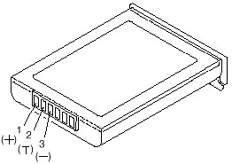
|
Pin
|
Voltage (V dc)
|
|
1
|
+10.0 to +18.0
|
|
2
|
Thermal Detection
|
|
3
|
Ground
|
o If voltage is less than +10.0 V dc, the battery
pack has been discharged or is defective.
o If the voltage is more than +10.0 V dc, go
to the next step.
3. Using an ohm meter, measure the resistance between battery terminals
2 (T) and 3 (N). The
resistance must be 4 to 30 kilohms.
o If the resistance is not correct, replace
the battery pack.
o If the resistance is correct, go to the next
step.
4. Install battery pack and plug AC adapter cable into computer to
charge battery pack.
o If the battery power status indicator
is blinking (orange) and battery charging indicator is on,
replace the battery pack. If the battery is charging normally, the
battery is OK.
Checking the
Backup Battery
1. Carefully place the computer bottom-side up.
2. Remove the bottom cover.
3. Disconnect the battery connector from the system board.
4. Measure the voltage of the backup battery. See the following figure.
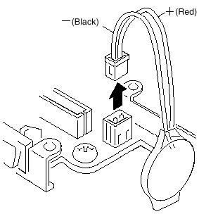
|
Wire
|
Voltage (V dc)
|
|
Red
|
+2.5 to +3.7
|
|
Black
|
Ground
|
o If voltage is correct, replace system board.
o If voltage is not correct, backup battery
was discharged by a short circuit or it is defective.
The backup battery is a CR2032 with solder tabs. The battery
is covered with clear heat shrink tubing. The battery is not sealed airtight
as the ends are open (not much).
Checking the
Standby Battery
Note: Make sure battery pack
is removed from computer before standby battery is removed.
1. Power-off the computer and unplug the AC adapter cable from the
computer.
2. Remove the battery pack.
3. Remove the indicator cover.
4. Disconnect the standby battery connector from the voltage converter.
5. Plug the AC adapter cable into the computer and power-on the computer.
6. Measure the output voltage at the connector on the voltage converter.
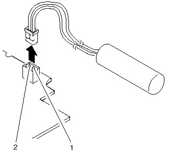
|
Pin
|
Voltage (V dc)
|
|
1
|
+4
|
|
2
|
Ground
|
o If the voltage is less than +4 V dc, replace
the voltage converter.
o If the voltage is more than +4 V dc, go to
the next step.
7. Power-off the computer and unplug the AC adapter cable from the computer.
8. Reconnect the standby battery to the voltage converter.
9. Plug AC adapter cable into computer and power-on computer. Allow
30 min for standby battery to charge.
10. Power-off computer and unplug AC adapter cable from computer -
remove standby battery.
11. Measure the voltage of standby battery.
o If the voltage is less than 3.5 V dc, replace
standby battery.
Checking the Quick
Charger:

If a humming or buzzing sound is heard from the quick charger
when it is operating, replace the quick charger. If the charger is operating
at a normal quiet sound level, do the following.
1. Perform steps 1 - 3 of Checking the
Battery Pack to ensure correct battery pack operation.
2. Connect power cord to quick charger and ac power outlet. Ensure
power-on indicator is on.
o If power-on indicator does not turn on, check
quick charger's power cord for correct continuity and installation.
o If the problem is not corrected, replace
the quick charger or the power cord.
3. Install the battery pack into the quick charger.
o If the charging indicator does not start
blinking, replace the quick charger.
QUICK CHARGER: The quick charger has two slots to charge two battery
packs simultaneously. Charging begins on the first battery pack installed,
then after it is completely charged, the other installed battery pack is
charged. A REFRESH BUTTON is provided for each battery pack slot
to DISCHARGE the battery packs before charging them. There are identifiers
and indicators that tell the charging status for each battery pack installed.
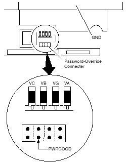
Checking the Voltage
Converter (700, 700C):
Use this procedure to isolate a problem with the ThinkPad
700, 700C voltage converter.
Note: If the problem only
occurs when using the computer with a good battery pack, replace the
voltage converter.
1. Power-off the computer.
2. Power-off all attached devices and disconnect them from the computer.
3. Unplug the AC adapter cable and remove the battery pack from the
computer.
4. Carefully place the computer bottom-side up and remove the bottom
cover.
5. Plug the AC adapter cable into the computer.
6. Power-on the computer.
Important Be careful not
to actuate the suspend switch (located between the Esc key and the LCD)
during the operation. When you turn the computer upside down with the LCD
opened, put
something under the computer to prevent accidentally actuating the
suspend switch.
7. Check the voltages of the voltage converter on the system board.
|
Signal
|
V dc Min.
|
V dc Max.
|
|
VA
|
+4.75
|
+5.25
|
|
VG
|
+4.75
|
+5.25
|
|
VB
|
+4.75
|
+5.25
|
|
VC
|
+3.42
|
+3.78
|
|
PWRGOOD
|
+4.00
|
+5.25
|
Note: Only VOLT is marked
on the system board.
Use the above figure to locate the VA, VG, VB, VC, and PWRGOOD signal
names.
o If all voltages are correct, the voltage
converter is operating correctly.
o If the voltages are not correct, go to the
next step.
8. Power-off the computer and unplug the AC adapter cable from the computer.
9. Check for a short circuit between GND and VA, VG, VB, or VC.
o If there is a short circuit, replace the
following FRUs one at a time to correct the problem.
Voltage converter
System board
o If there is no short circuit, go to the next step.
10. Check the output voltage of the AC adapter cable (see Checking
the AC Adapter).
o If the output voltage is correct, go to the
next step.
11. Replace the following FRUs one at a time.
Voltage converter
System board
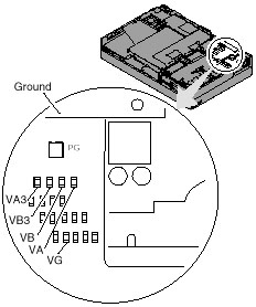
Checking the Voltage
Converter (720, 720C):
Use this procedure to isolate a problem with the ThinkPad 720, 720C
voltage converter.
1. Power-off the computer.
2. Power-off all attached devices and disconnect them from the computer.
3. Unplug the AC adapter cable, then remove the battery pack from the
computer.
4. Carefully place the computer bottom-side up and remove the bottom
cover.
5. Plug the AC adapter cable into the computer.
6. Open LCD half-way, stand computer on its front edges so suspend
switch isn't activated.
7. Power-on the computer.
8. Check the voltages of the voltage converter on the system board.
See the following figure.
Notes:
a. Make sure the suspend switch (located to the left above the keyboard)
is not activated during
measurement of the voltage.
b. Only PG is marked on the system board. Use the following figure
to locate the VA, VG, VB,
VA3, and VB3 signal names.
|
Signal
|
V dc Min
|
V dc Max.
|
|
VA
|
+4.75
|
+5.25
|
|
VG
|
+4.75
|
+5.25
|
|
VB
|
+4.75
|
+5.25
|
|
VA3
|
+3.42
|
+3.78
|
|
VB3
|
+3.42
|
+3.78
|
|
PG
|
+4.00
|
+5.25
|
o If any voltage is not correct, go to step
9.
o If all voltages are correct, the voltage
converter is operating correctly. If the power problem did not reoccur,
reconnect the devices removed in step 2 to isolate a device problem.
o If all the voltages are correct and the power
problem still exists, replace the following FRUs
one by one.
System board
Processor card
9. Power-off the computer and unplug the AC adapter cable from the
computer.
10. Check for a short circuit between Ground and VA, VG, VB, VA3 or
VB3. The following table shows which FRUs can cause a short at each signal.
o If there is a short circuit (less than 10
ohms), remove the FRUs indicated one at a time until
the short circuit disappears. Replace the FRU causing the short circuit.
|
FRU
|
VA
|
VG
|
VB
|
VA3
|
VB3
|
| Voltage converter |
x
|
x
|
x
|
x
|
|
| Processor card |
|
|
x
|
|
x
|
| System board |
x
|
x
|
x
|
x
|
x
|
| Video card |
x
|
|
x
|
x
|
x
|
| Base memory card |
x
|
|
|
|
|
|
Keyboard control card
|
x
|
|
x
|
|
|
| Math coprocessor |
|
|
x
|
|
x
|
| Diskette drive |
|
|
x
|
|
|
| Hard disk drive |
|
|
x
|
|
|
| LCD |
x
|
|
|
|
|
| Indicator assembly |
|
x
|
x
|
|
|
11. If there is no short circuit, replace the following FRUs one at
a time.
o Voltage converter
o System board
9595 Main Page
|