9533 (PS/2e)

9533 Planar
   J22 Flash Memory Select Jumper
9533 FAQ Tribute
Starter, Diagnostic, and Utility Disks
9533 Under Linux (To Peter's Site!) 
4 Slot PCMCIA Adapter
   PCMCIA Drivers for DOS/OS2/Win3.1x
      Testing the PCMCIA Adapter
      Switch Settings
      Lock / Unlock PCMCIA Cards
         Disabling Solenoid Locks
   PCMCIA under W95
NT3.51 on the Big E
486SLC2 Characteristics
   16MB RAM Limit
   387SX Math Coprocessor
Memory
Onboard XGA-2
   Patch for 9533 XGA-2 Files
Hard Drive
  Disk Manager for >528MB
   HD Cable
Floppy Drive
   Floppy Tape Connector
   Removing Floppy Tape Connector
   Reseating the Floppy Tape Connector
Open the Case
Remove the Power Supply / Floppy/ Hard Drive Mount
Power Supply Limitations
Testing the Power Supply


9533 Planar
Note: Some Model 35 and Model 40 computers use this system board. 
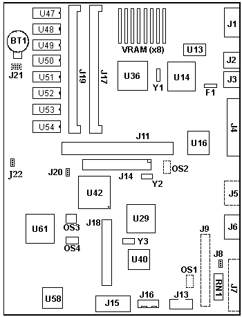
 
BT1 Battery
F1 Keyboard fuse
J1 Display port
J2 Mouse port
J3 Keyboard port
J4 Parallel port 
J5 Solder pads for Serial port 
J6 Serial Port
J7 Solder pads for ext SCSI
J8 Solder pads for 3 pin header
J9 Solder pads for 50 pin int SCSI
J11 Bus-adapter socket
J13 Control connector (P3)
J14 IDE Connector
J15 Power P1 connector
J16 Power P2 connector
J18 Floppy connector 
J17,19 72 pin SIMM sockets
J20 Password-override 
J22 Flash Memory Select Jumper 
OS1 Solder pads
OS2 Solder pads
OS3 48.0000 MHz osc
OS4 50.0000 MHz osc
RN1 Term resistor
U13 Sony CXK58257AM-10L
U14 XGA-2 controller
U16 8042AH
U42 80387SX socket
U29 VLSI VL82C306-FC1
U36 50G5725
U40 486SLC2
U47-54 4MB memory 
U58 82077SL Floppy controller
U61 41G3933
Y1 4.0 MHz (?) xtal
Y2 14.31 MHz xtal
Y3 32.768 KHz xtal

J22 Flash Memory Select Jumper
From Daniel Basterfield
Louis, 
   One for the web page: I pulled a book out of an old bookshelf, and half a dozen other books fell over, in the midst of which was a shrink-wrapped PS/2 E Technical Reference. Woohoo! 
   This jumper is used to select whether flash memory or EPROM is accessed through the ROM addresses. If the jumper is across both pins when the system is powered on, flash memory is mapped to address hex 000E0000 to 000FFFFF and hex FFFE0000 to FFFFFFFF. The system is shipped with the jumper installed (flash memory is selected). If the jumper is removed, the EPROM responds to these addresses. 
   Note: Do not change the position of the jumper while the system is powered-on; unpredictable operation will occur 

Pin
Signal Name
1
select flash memory
2
ground

Adjustable Floor Stand Accessory (P/N 91F1028) 


PS/2 E (Model 9533) FAQ

Don Hills posted the original PS/2 E (Model 9533) FAQ on CompuServe. His work provided the base for my adventures with the "Big e". 

 The PS/2 E (model 9533) system unit has a PS/2 model 35 motherboard. 486SLC2 25/50 MHZ CPU, 4 MB memory soldered in, 2 sockets for IBM PS/2 style SIMMs (2, 4 or 8 MB), to a maximum of 16 MB of total system memory.  IDE controller, but only enough room inside for a laptop 2.5 inch IDE drive.  XGA-2 video w/1MB of VRAM on motherboard.  One ISA bus slot, depending on the model it may contain: 
 - Nothing 
 - An IBM ISA Token Ring 16/4 adapter 
 - An IBM ISA Ethernet adapter 
 - An IBM 3270 emulation adapter 
 - A PCMCIA adapter with (4) Type 2 slots (2 in the front, 2 in the rear). 
   (Ed. PCMCIA controller is an Intel SE82365SL. Intel(R) discontinued the 82365SL and 82365SL DF in 1995.  The rights, tooling and technical data for the 82365SL were given to Rochester Electronics, Inc.* (REI). ) 


486SLC2 Characteristics
From Peter
See: the 486SLC2 processor in the 33 is *technically* a souped-up 386SX. It is an interesting mix of technologies.
- external bus is from the 80286: 16 data and 24 address lines 
- internal 16K Level-1 cache is inherited from the 386SLC 
- 32-bit processor core is compatible with a 486SX (no integrated FPU) 
- power-management comes from the 386SL laptop processor 
- pin-out and case (PLCC) comes from the 386SX 
- additional MathCo is a 387SX-25 
- internal clock-doubling is taken from the 486DX2 line 

16MB RAM Limit
   With only 24 address lines the total RAM is limited to 2^24 bytes =16.777.216 bytes = exactly 16.0 MB. That's the directly addressable memory area. The 16-bit external data-path allows only 16-bit slots (the "short ones"). 
   However: because of the 486SX-style core and instruction set it can handle true-32 bit software written for 486 systems. The machine can even carry out 32-bit instructions across the 16-bit data-bus (with two bus-cycles instead of one) - but it still is a 386SX system *technically*. 

MEMORY:
   There are 2 slots for memory that support 2, 4 or 8 MB SIMMs. If the total of the SIMMs and the onboard 4 MB memory exceeds 16 MB the system will tell you that only 12MB of the socketed memory is useable. It will work fine no matter if you have 12MB or 16MB in the sockets . 
   "Generic" or "industry standard" memory will not work- it must be "PS/2 style" 70 ns parity memory.  It uses the same memory as other PS/2s of the same vintage- if in doubt, ask the supplier for memory for an IBM PS/2 model 56 or 57 or 76 or 77 (8556, 8557, 9556, 9557, 9576, 9577).  These were very common models. I have also used an 8MB SIMM from a 8595. 
   The system reserves .5KB of memory when BIOS/POST is copied to RAM for execution in systems with less than 16MB of planar memory. You will have 15.5MB available when 16MB of memory is installed. 

387 Math Coprocessor
  After a bit of diddling around, I got a Intel 387SX to run. Watch your pin orientation... Pin 1 to pin one. Usually, pin 1 is marked either with a dot or the corner of the chip is not a 90 degree corner. Like it was "cut" off.  Also, the 387 socket is a 121 pin PGA socket. I don't think this helps in using an SLC3 upgrade. At all. 


HARD DISK DRIVES: It'll accept any 2.5 inch IDE laptop drive, provided it is not too "high" (thick), as it has to fit under the diskette drive. I think the drives come in 2 common heights- 12 mm and 17 mm- and the space available is only about 15 mm high. 

Disk Manager for >528MB
   If the drive is over 512 MB you will also need "Disk Manager" or "EZdrive" or similar software in order to be able to access more than 512 MB of the drive. (The PS/2 E does not have "large disk" or "LBA" support in BIOS. Disk Manager is used for IBM IDE hard disk drives) 

HD Cable 39G6566 has the right power tap-off. Laptop IDE drives have the power wires on the same plug as the signal cable, but the 9533 is "desktop" IDE where the power is separate.  The IBM cable splits out the power wires to a special connector from the power supply. The stock IBM drives can be found here IBM H2172-A2 (172MB), H2258-A3 (258MB) & H2344-A4 (344MB)


Floppy Drive
   The BIOS DOES have support for the 2.88MB floppy. IBM Thinkpad 720 diskette drive. The 1.44MB floppy is a Teac FD-05HG-263-U or  IBM Part 1619640.

Floppy Tape Connector
You can't build one, it's a ribbon printed circuit IBM Part 39G6564

Floppy Tape Removal
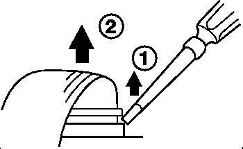
   Notice the off-white piece at the rear edge of the floppy. It actually works as a wedge. To release the tape, use a small screwdriver to carefully work up that off-white piece from the black base. Go slow. The piece is a captive part, and only pry it up about 1/10th of an inch. Just enough to free the tape. (OK, maybe 1/8th of an inch) 

Reseating Floppy Tape
    Now with the tape loose, carefully seat it square in the socket. While still maintaining downward pressure on it, push the wedge down until it seats on the black base. That's it. 

Note: I had a strange problem with my floppy. Tried reseating the tape, no go. I was turning it over, looking for model numbers, when I heard something rattle. Turns out somebody had stuck a safety pin in the floppy. So if small children have been in the area, just remember they like to stick small objects in anything with a door. VCRs. Tape decks, Sewing Machines. Computers.... 


 BUS: The machine has a single ISA slot. 


Power Restrictions
From Don Hills 
   I installed a Sound Blaster 16-SCSI adapter.  The CDROM drive cable ran out of the back of the case to the drive, which I put in an external box with its own power supply.  It sits on top of the PS/2 E. Note that the internal power supply in the PS/2 E is 24 Watts.  I had to disable the internal speaker amplifiers on the sound card, it was hanging the machine when loud sounds were played.  I now use external amplified speakers.  Most recent sound cards no longer have internal amplifiers anyway- people prefer external amplifiers to get more power, and control over volume/bass/treble etc. 


DISPLAY ADAPTER: The planar video is XGA-2, for DOS/Windows you will need the XGA device driver diskette (latest version is V2.12.) 

XGA-2 Patch
xgapatch.com XGA Patch files for 9533 Starter Disk 
   To use the XGAPATCH.COM, make sure that it's on the same floppy or in the same directoy that the Starter Diskette files are on. Run XGAPATCH, and it searches for and automatically "patches" two files for you. That's it.. 

>Yes - but the XGA-2 driver with Winblowz is for the MCA-version only. The 9533 has ISA XGA-2 and it seems it does not work very well together. I'd managed toget it going under Win95 IIRC ... I deleted the Wincrap from it and installed Linux ... 

From Don Hills (looks to be a long thread) 
   It has a problem under OS/2 as well, specifically in motion video. On Micro Channel (such as 9556), the bus is fast enough for OS/2 to use the 64 KB window below the 1 MB line to push video data to the adapter. On ISA such as the 9533, it won't work unless you remove 4 MB of memory to allow the XGA-2 to use the 1 MB window between 14 and 15 MB. Without it, you just get a black video window with no error. 
   (XGA-2 has 3 "apertures" or direct video buffer access paths: a 64 KB "movable" window below the 1 MB line, a 1 MB aperture below the 16 MB line, and a 4 MB aperture just below the 4 GB line (when in a 32-bit addressing system). 

As for hard disk noise, the APM for DOS and OS/2 works fine. 

VESA POWER MANAGEMENT
   This is a technique proposed to the VESA for adoption as an industry standard.  It involves the system unit or graphics adapter card to which the display is connected.  The stages towards shutdown are controlled by the state of the H and V sync lines on the incoming video signal as follows: 

STEP
H-SYNC
V-SYNC
DISPLAY STATUS
VESA STATE
1
Active
Active
Normal Operation
On
2
Inactive
Active
Video - Instant Restart
Off - Standby
3
Active
Inactive
Video & Scans - Instant Restart
Off - Suspend
4
Inactive
Inactive
Only Micro active - Delayed Restart
Off
       At step 3, power consumption is reduced below 30 watts. 
       At step 4, power consumption is reduced below 8 watts. 


DIAGNOSTIC AND SETUP DISKETTES: It is an ISA bus system and, in common  with IBM's other PS/2 ISA bus systems, does not have a Reference diskette.  It does have a "Starter" diskette, and a "Utility" diskette which contains, amongst other things, management utilities and drivers for the 4-slot PCMCIA adapter that some models shipped with. 

ps2estrt.exe  9533E Starter Diskette v1.0 
ps2eutil.exe 9533E utilities disk version 1.0 


4 Slot PCMCIA Adapter

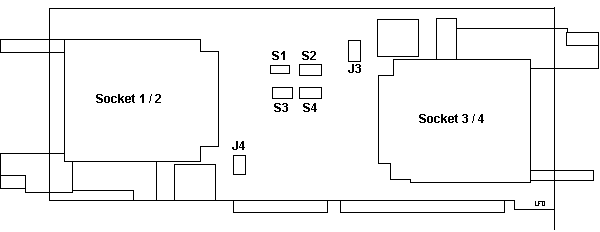
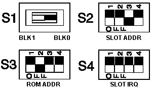
Switch Positions on PCMCIA Adapter
  I have nothing yet on what values correspond to the slot, rom, or IRQ switch settings. 

From Daniel Basterfield
   I did come across a sideways hint at the purpose of one of the DIP switches on the PCMCIA card, but it's the less exciting of the four. There would appear to be 32KB of flash ROM on the card; this is described as holding the 'socket services code' - I would interpret this as it being firmware to sit between the SS driver API and the hardware of the PCMCIA controllers. It is apparently addressed as two seperate 16KB blocks when being (re)programmed; one of the switches has BLK 0 / BLK 1 markings. 

PCMCIA Drivers for DOS/Win3.1x
   These drivers are not as good as with the ones from ISA2SLOT, but the disk does have the Lock/Unlock and Security Manager Utility for OS/2 and Win3.1x

utte131.exe PCMCIA Device Drivers for 9533 
To create a diskette from the uttps131.DSK file: 
- Insert a blank diskette into the A: drive 
- At a DOS prompt type "LOADDSKF uttps131.DSK A:" and press Enter 
- Follow the instructions on the screen 
(Loaddskf.exe is included in the UTTE131.EXE file.) 

Using ISA2SLOT
   I used the Play At Will software that came with the MCA PCMCIA Adapter. If you search the subdirectories, there is all the *.idp files. One is for the IBM 4 slot adapter. Bingo! 
   A problem using the PCMINSTW.EXE (Win 3.1x) program was that it choked trying to rename the system.ini and config.sys files. How to work around that- When it asks to make changes to config.sys (and system.ini) tell it no. Then it will save the changed files as config.pcm and system.pcm in the EZPLAY directory (or wherever you told the instal program to put it). 
  Then use File Manager to move the original config.sys and system.ini to your temp directory (safety first) move the *.pcm fles to the correct locations, rename them, dump out of Winblows, reboot, and it should work. Did for me. 

Win95 PCMCIA Support
  After I got through some conceptual difficulties, I got it to work. I chose to install it under Add New Hardware, and I didn't let Win95 autodetect it (Though it works that way, it identifies it as a PCIC or compatible, NOT Intel.) 
   The default choice of I/O 03E0-03E1, IRQ works. Windows will also instal Socket Services automatically.You do not need any DOS drivers whatsoever. 
   IF the device you are using is visible under Explorer, but comes up as not ready when you click on it, try reformatting it. This was one of my problems. I could see the PC hard drive, used it to transfer W95 setup files, but it would not respond to Exploiter. Until I reformatted it. 


Testing the PCMCIA Adapter

The PCMCIA adapter acts as a bus from the planar to the option adapters. 

   If the computer has a problem, carefully remove and reseat the riser card, any PC Cards, and the PCMCIA adapter. If, after reseating these boards, you get an 80XX error code, replace the PCMCIA adapter. For any other symptom, continue with the steps below. 

If you suspect a problem with the PCMCIA adapter, do the following. 
   Power-off the computer. 
   Remove all option adapters from the four PCMCIA adapter slots. 
   If you have a PCMCIA wrap plug, insert it into slot one. 
   Insert the PS/2 E Type 9533 Advanced Diagnostics diskette into drive A. 
   Power-on the computer and follow the instructions on the screen. 

If the PCMCIA adapter diagnostic tests find no problem, suspect a PC Card option adapter connected to the PCMCIA adapter. To test the PC Card: 
Power-off the computer. 
Insert suspect PC Card into a rear slot. 
Insert the appropriate PC Card diagnostics diskette into drive A. 
Power-on  computer and follow the instructions on the screen. 

If the PC Card option adapter diagnostic tests find no problem: 
   Power-off computer and insert PC Card into a front slot. 
   Power-on the computer. If the PCMCIA adapter diagnostic tests still find no problem, replace the PCMCIA adapter. 
  If a PC Card option adapter fails in a front slot and it did not fail in a rear slot, replace the PCMCIA adapter. 
   If a PC Card fails in both a front and a rear slot, replace the PC Card. 

Editor's Note: And just trot right over to your local IBM rep, and he (or she) will be glad to sell you one for $500+. 

Note: Before you replace a PC Card, be sure its application software and any required drivers are installed correctly on the computer. 

Lock/Unlock PCMCIA Cards
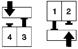
    PC Cards can be locked in place for security purposes with the lock mechanism. Any of the four lock mechanisms can be unlocked manually. To unlock a locked mechanism, use a pen or screwdriver (pencil lead is made from graphite, which is a conductor. Keep it away from electrical switches) to press its lock solenoid in the direction of the arrow shown below. (Solenoids 1 and 3 are shown locked. Solenoids 2 and 4 are shown unlocked.) 

Disabling Lock/Unlock
   The Lock/Unlock software does NOT work under W95 or NT. If you don't care about leaving them unlocked, simply remove the solenoid headers from J4 (front two sockets) and J3 (rear two sockets). As this is NOT an MCA system, this does not cause any prompts for the starter disk. 

  I have disconnected both solenoid headers on my e and have no problems under Win95. 

   After some switch twiddling, I had to pull a card out without being able to use the blue buttons (card was locked). Trying to reinsert the card didn't work. I looked real close- when the solenoid is in the locked position, there is a little "finger" that sticks out to retain the PC card. It's on the guide that has the eject buttons.
   If you are curious, open the case and use a small screwdriver to work a solenoid. The finger is toggled with the solenoid. As long as the case is on, it's very hard to get a grip on a card with your fingers (pliers are another story).


NT 3.51 on the Big "e"

I thought this was a twisted joke. 

Daniel Basterfield

Well, it was not tricky, really. Rather than attach a CD-ROM drive (couldn't figure an easy way of doing that), I simply copied the NT i386 directory to the hard drive, and installed from there - I chose to use a 105MB PCMCIA drive as a big diskette, and created a suitable DOS boot disk. I've swapped the hard drive for a 512MB one, so space is not an issue. I'm using the normal 4-port PCMCIA adapter, but haven't checked (as far as I recall) if all four ports are available. I'd suspect only two ports are recognised. 

I've just tried shoving a couple of PCMCIA devices into it, and of course the damn security clips are activated, so I can't. Arse. I haven't had any luck running the DOS or Windows lock  Programs under NT. I can't even get the DOS one to run under DOS! at the moment it's only got the PCMCIA t-r adapter in it, and I can't get the bloody ethernet card back in to prove it was working when I last used it. Argh! 

Um, NT 3.51 isn't exactly nippy, but it serves well as a network device. 

>  are you implying that you are using a pcmcia adapter under 3.51? Do tell... 

   Nothing to tell - it saw it, and installed the drivers - the PCMCIA device is started, basically. I'm not sure how to check whether it's running as two instances of a two-port driver, or one instance of a four-port driver, and I can't get any extra cards into it at the moment. I have to say, I get so bloody frustrated with the 4-port card locking the cards away, I have seriously considered slinging the card and just making do with an ISA Digital 2-port 82365sl that I have spare. When Ipress the 'eject' button, I mean 'eject'... :-( 

To be honest, the trickiest bit is remembering that when I apply SP5 to it, it overwrites the t-r adapter driver with a duff old version, so I lose my remote control. Obviously the punishment of having to get a monitor cabled up near it is enough for me to remember that for a week or so... then I forget and do it all again - Doh! 

> I suppose I could try 4.0 on my e. As it uses the i82365SL pcmcia chipset,  it might work. 

Yup - it will. I recall that NT 4 was using around 24MB with me logged on, and without much configured in the way of services. Thrash! I tried NT 3.51 with the Shell Update - a sort of 3.51/4.0 hybrid, but that Explorer shell ate up the RAM, and only shaved 2MB off the NT 4 memory usage. Still thrashy. 

I'll give you any assistance I can with NT on this box. My recollections of the installation are a little hazy, as that was about four months ago, so apologies if any of this is annoyingly vague. The box just runs and runs - it's been rebooted only to move house, and again whenever I pull the wrong power cord. I haven't got it to boot without the keyboard present, so I just leave the space saver plugged in and tucked out of the way. 

I suppose I ought to carry on the quest, and get it sorted out. I'll need to shrink the partition to make way for a Win3.1 area, so I can boot that and eject my cards without using a screwdriver. Cleaner, but not ideal. 

I did have OS/2 4.0 on it for a while - got really narked trying to install LanServer 5 onto it - whatever I did, it refused to play ball unless it could see the CD. Hmm. The PCMCIA adapter support was a dream, though! 


Opening the 9533
  Hopefully, it's unlocked. Who has a key? Open the front cover. See the white latch in the center? (under the black cover latch). Pull up on the white catch while pushing it back (latch is mounted to the frame). Push forward on the case while pushing back on the latch. 
  Do NOT try to pry the case open at the back! You do NOT need any tools to open the case! 


Power supply / floppy / hard drive mount Removal
   Look at the rear of the case. There is one standard screw to the upper left of the power socket. Unscrew it. Now you can lift the front of the mount up and pull the entire mount up AFTER you unplug the cables! 
   First, disconnect the floppy tape connector. Look here
   Tip the front of the mount, then pull the HD cable out of the planar. 
   Look at the left side of the mount. All sorts of cables, eh? The main power leads go into a black connector. Notice it has tabs at each end. Squeeze those tabs inward while pulling the entire connector up. May have to wiggle it some. Also, pulling the mount towards the left side gives you more room to grab the power cables.... 
   Next, there is a white power connector to the left. I just grabbed the wires and pulled straight up. Crude, but it works. 


 Andrew Daugherity (awd42_007@hotmail.com)
here's a brief description:
-There are a couple of "rails" on the bracket attached to the power supply,
I cut the left one down about 1/2 inch to make room for the cables.
-I moved the floppy down to where the hdd was and attached it from the
bottom instead of the sides.
-I put the two hdd's on top of the floppy, rotated 90 degrees from the
original disk mounting orienation.  They are positioned with the pcb's
facing up and the connectors pointing toward the ISA slot.
-I used a generic IDE cable plus two 2.5-inch to 3.5-inch adapters (the kind
that let you use 2.5-inch disks in a desktop machine) and a power splitter
to get one power plug for both disks.  I wired this up to the connection
from the p/s.
-I cut off some of the aluminum "fingers" on the inside of the cover to
allow access to the floppy in its new lower position.
-Best of all, I left the old fdd mounting holes, so I can still go back to
the old configuration if I wanted to.
-The p/s seems more than capable of supplying power to the 486, XGA/2, fdd, two hdd's, and a pcmcia NIC and modem.

9595 Main Page