|
Open The Case
Open the Case Open and unlock the door, removing it by
lifting it up and off the hinges.
Unlatch the catch. (Tricky, I'm a poet and I don't know it). Yes, this is from another machine, BUT... same principle.
Grasp the sides of the front cover and pull it forward.
(Or, you may grasp the handle at the top left corner of the server.) Detach
the front cover's bottom hooks from the grooves located on the bottom of
the server, and lift the front cover off the bottom of the server.
Pivot the side cover away from the front of the server. Remove the cover by carefully lifting it up and off the hinges.
Installing a Floppy Drive
The Enhanced 2.88MB Diskette Drive requires an operating
system, such as OS/2 2.1 or IBM DOS Version 5.02 or later to enable
use of the software-eject and eject-disable features.
Installing a CD-Rom 
CD Rom ID off Backplane
Remove CD Storage Compartment
If you are installing a CD Rom drive in bay B1,
remove the CD Storage Compartment
Insert Drive into Bay B1 
Extra Power Supply Required Before installing drives in bank D, you must install an additional 220-watt power supply. Server 500 Bay Locations 
Internal drives are installed in bays. A diskette drive and a CD-ROM drive are preinstalled in bay A in all models. A removable CD storage compartment is shipped in bay B1. You can install two drives in bay B. You can install hot-swappable hard disk drives in banks C, D, and E only. Banks C, D, and E each contain six bays. Banks C, D, and E support hot-swappable drives only. You do not have to turn off the server to install hot-swappable drives in bank D. However, you must turn off the server when performing the steps that involve installing or removing backplanes, cables, the fan assembly, and adapters. Bank C supports up to six drives. However, the total number of SCSI drives that you can install in bay B and bank C is six. The number of preinstalled hard disk drives in bank C varies according to the model you purchased. You can install up to six drives in bank D and up to six drives in bank E. Note: The bank letter-designations
are located on both vertical rails on the front of the server. The
bay-slot numbers are located on the top of bank C and the bottom of bank
E.
Adjusting the Cover Plate
Remove Fan Assembly
Warning: To avoid damage and ensure proper server operation, handle the fan assembly carefully. 2. Remove the two screws that hold the fan assembly in place. 3. Remove the fan assembly by pulling it up and out.
Install a Backplane 
a. Align the top screw hole on the left side of the backplane with the top screw hole on the left side of bank D. Make sure all the pins are lined up correctly. b. Secure the backplane with one screw.
500 Backplane Front View (towards drives)
Rear View (towards fans)
Note: The DASD status connector is used in disk-array models only. SCSI ID Jumper
ROM Address
Jumper Setting
Termination (Hot-Swap
Back Plane)
Non-Array Fast/Wide Cable Configuration Single Channel, Single
Fast/Wide Adapter Cable Configuration
Cable routing in a non-disk-array model, with the backplane
in bank C 1 cabled to an IBM SCSI-2 FWSR 2 in expansion slot 1.
Two Channel, Two Fast/Wide
Adapter Cable Configuration
This view shows cable connections to two SCSI-2 adapters
(IBM SCSI-2 Fast/Wide Adapter/A): cable routing from the second adapter
1 to the backplane in bank D 2.
Three Channel, Three Fast/Wide
Adapter Cable Configuration
Non-disk-array model, with banks C and D populated, and
both banks connected to SCSI-2 adapters. A third SCSI-2 adapter 1
supports the backplane in bank E 2.
Fast/Wide RAID Adapter Cable Configuration Single Channel, Single RAID Adapter Cable Configuration
Cable routing in a disk-array model, with the backplane
in bank C 1 cabled to an IBM SCSI-2 FWSR Adapter/A 2 in expansion slot
1. A DASD status cable 3 connects the adapter to the backplane.
Dual Channel, Single
RAID Adapter Cable Configuration
Cable routing in an array model with backplane installed in bank D 1. A DASD status cable 2 connects adapter to backplane. Notes:
Two Channel, Two RAID
Adapters Cable Configuration
Cable routing in a disk-array model, with cable connections
to two SCSI-2 adapters (IBM SCSI-2 Fast/Wide Streaming-RAID Adapter/A):
cable routing from the second adapter 1 to the backplane in bank D 2.
A DASD status cable 3 connects the adapter to the backplane.
Three Channel, Two RAID Adapter Cable Configuration
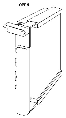
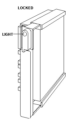
Install Hot Swap Drive a. Move the tray's knob to the open position. b. Position the drive tray assembly vertically, with the connector facing the rear of the server. c. Align the side of the tray with the raised guides on the bottom of the bay. (Note the arrows pointing towards the backs of the bays.) d. Slide the drive tray to the rear of the bay until it connects to the backplane. Be sure it is connected properly to the backplane. e. Move the tray's knob to the locked position. 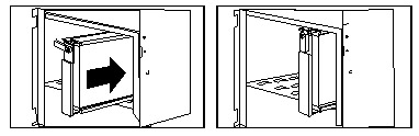
Note: If you did not turn off your server before installing the drive, the light on the knob of the drive tray illuminates, indicating that the drive was installed correctly. Note: If you have a disk-array
model, you must reconfigure your disk arrays after installing hard disk
drives.
Remove Hot Swap Drive You do not have to turn off the server to remove a drive from banks C, D, and E. Warning: Before you hot-swap a drive, make sure it is defective. If you partially or completely remove a good drive instead of a defective drive, your server might lose valuable data. Determining Defective Drive, Array
Determining Defective Drive, Non-Array
If you partially or completely remove a good drive instead of the defective one, your server might lose valuable data. This situation is especially relevant if you assigned RAID level 1 or 5 to the logical drives in your disk array. However, the RAID controller can rebuild the data you need, provided that certain conditions are met. See Starting the RAID Configuration Program for further details. To remove a drive from bank C, D, or E, do the following steps: 1. Find the defective drive you plan to remove.
Note: If you have a disk-array model, you must reconfigure your disk arrays after removing hard disk drives. See Starting the RAID Configuration Program for details. - I vaguely remember a snippet on allowing the drive to spin down after you rotate the knob to the unlocked position.
RAID Recovery Procedure Not Effective Symptom: A single drive failed,
but 2 RAID fixed disk drives appear as DDD (Defunct the drive is not responding
to commands). Routine recovery procedures are ineffective in
NOTE: The system may have run without problems for some time. Problem Isolation AIDs
Fix: / Background The RAID controller requires two cables to be attached to the DASD backplane in order to maintain control of the RAID subsystem, the SCSI signal cable (wide), and a much smaller Status cable. The backplane in Bank C must be attached to SCSI Connector Channel 1. If installed, DASD backplane in Bank D would be attached to SCSI Connector Channel 2. The same is true of the Status cables. Status connector 1 must be attached to DASD backplane C and Status Connector 2 must be attached to DASD backplane D, if installed. The signal cable and status cables for each channel may not be connected to the same backplane. (For example: The Status cable for the backplane is mistakenly connected to bank D, and vice-versa). In this case, the RAID adapter is not communicating with the correct backplane (but has no way of knowing this), so erroneous status information is being presented to the RAID adapter. Attempting to rebuild a fixed disk with the cables connected in this manner will probably result in data loss. In systems which have more than one DASD backplane installed, make certain that the RAID Channel 1 (SCSI) signal cable and the RAID Channel 1 Status cable are both attached to the same backplane (are not crossed). All artwork on this page is from IBM documentation. IBM retains all copyright to them. |