|
8227 Access Point
195-082
IBM WIRELESS LAN ENTRY PRODUCT FAMILY
Wireless LAN Communications HTML111PDF
E2SB5001
Wireless LAN Entry 8227 Access Point User's Guide
IBM
Wireless LAN Kit Using the Wireless Lan under OS/2
EZ331800
LAN Concepts and Products: Routers and Gateways
A3A4IM01
OS/2 LAN Requester User's Quick Reference
A3A4IM02
OS/2 LAN Requester User's Guide
A3A61M02
OS/2 LAN Server Planning, Installation, and Configuration
EZ30BW00
Inside OS/2 LAN Server 4.0
Wireless LAN Entry
Access Point
8227 INT
25H4211
Access Point
8227 PAT
13H5895
(Extended Range)
Wireless LAN Adapter PCMCIA
8090 PN 80G0900
Wireless LAN Entry PCMCIA Adapter 4285
PN 92G7787
8227 Front

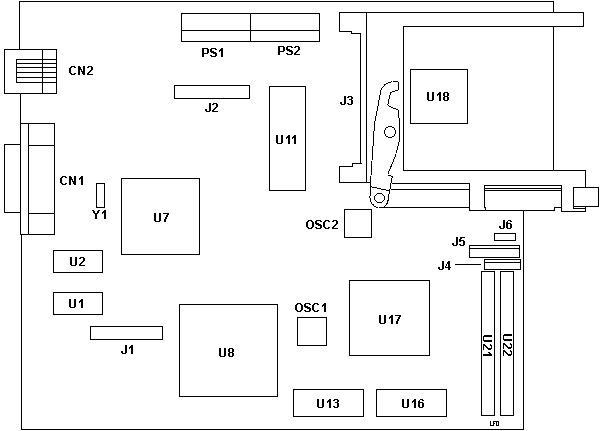
8227 Sysboard

CN1 AUI port
CN2 RJ45 port
J1,2 Known but to God and IBM
J3 PCMCIA slots
J4,5 LED Panel Header
J6 Unk two pin header
OSC1 33.00000 MHz Osc
OSC2 14.31818 MHz Osc |
U1,2 Winbond W2465S-70LL
U7 NS DP83905AVQB AT/Lantic
U8 486SX-33
U11 BIOS IBM AP Q21E
U13,16 MT4C16257DJ-6
U17 UMC UM82C491F 9513-ATA
U18 Cirrus CL-PD6710-VC-B
U21,22 DR256Kx16_ZIP |
J6 is open on mine, the jumper is on one pin only.
BIOS Sticker on the board says PhoenixBIOS A486SX, G89295. The BIOS
eprom is 940809.
J1 and J2 are both 20 pin headers with pin 4 missing.
U21 and U22 are solder pads only.
spread spectrum frequency-hopping radio used by the Wireless LAN Entry
operates in the 2.4GHz unlicensed frequency band.
Each access point can support up to 16 active users.
Wireless LAN Entry 8227 card

The 8227 card is functionally identical to the IBM Wireless LAN Entry
Adapter that the clients use, except that it has additional flash memory
on it. The 8227 card comes preloaded with operational software loaded on
the flash memory. When the 8227 is switched on, it verifies that the card
is in Local Program Load (LPL) mode and loads the code from the card.
The 8227 can load its operational software and configuration information
in one of two ways - local program load or remote program load.
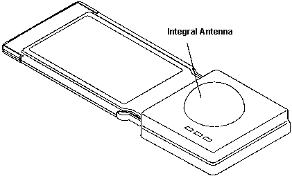
Integral Antenna
The integral antenna is built in to the transceiver which
in turn is part of the PCMCIA Wireless adapter and is the only one which
can be used in a
workstation. It transmits over a 360° area with equal signal strength
in all
directions. In many environments this antenna will be used in both
the
workstations and the 8227s. An 8227, so equipped, should be mounted
high up. Install it against a ceiling, for example, as close to the center
of the required operating area as possible. The workstations in the cell
can be arranged anywhere within the area of coverage. This antenna should
only be used in the horizontal plane.
Wireless LAN Entry 8227 XR card

The 8227 extended range model supports an external gain antenna.
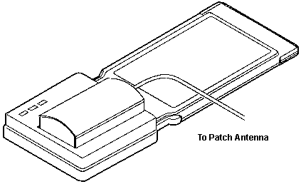
Patch Antenna
The patch antenna is an alternative to the integral antenna
for the 8227. It
connects to the PCMCIA Wireless adapter by cable, so it may be installed
some distance from the 8227 itself. The range of transmission is asymmetrical,
forming two lobes of 180° each. One lobe takes the shape of a pointed
dome and has a range somewhat greater than the integral antenna. The other
lobe is a flattened dome and covers a much smaller area. This antenna is
typically mounted high up against a wall and oriented such that the largest
lobe points in the direction of the largest workstation concentration.
Local Program Load (LPL) -- This
is the default loading mode. The operational software and configuration
information for the 8227 are contained on the 8227 card you received as
part of the kit. In LPL mode, the 8227 loads its operational software and
configuration information directly from the 8227 card installed in its
adapter slot. Chapter 3 describes the procedures you will need to follow
to perform an LPL installation of the 8227 card.
Remote Program Load (RPL) -- If
you change the loading mode to RPL, the operational software and configuration
information are automatically obtained by the 8227 from a file server on
the local Ethernet segment (see Figure 2-1 in topic 2.0). The software
and configuration files on the
8227 card are ignored. Chapter 4 describes the procedures that you
will need to follow to perform an RPL installation of the 8227 card.
Wireless LAN Entry 8227 card, WLE/XR
The 8227 card is functionally identical to the IBM Wireless
LAN Entry Adapter that the clients use, except that it has additional flash
memory on it. The 8227 card comes preloaded with operational software loaded
on the flash memory. When the 8227 is switched on, it verifies that the
card is in Local Program Load (LPL) mode and loads the code from the card.
LED Meanings
|
Name
|
Symbol
|
State
|
Meaning
|
| Software State |
 |
On
|
8227 card software installed and configured. |
|
|
Off
|
8227 card software not installed or configured. |
| Cell Leader |

|
On
|
Adapter is installed in an 8227, which is always the cell leader. |
Data
Transmission |

|
On or Blink
|
8227 card transmitting data. |
|
|
Off
|
8227 card receiving data or idle. |
8227 Card Removal
1. Make sure the 8227 is off.
2. If the external patch antenna is being used, disconnect the
antenna cable from the adapter cable.
3.Push the adapter ejector button.
4.Pull the adapter out of the adapter slot.
5.Put the plastic adapter-slot cover over the adapter slot.
9595 Main Page
|


