9577

Lacuna vs. Bermuda
   Upgrading Planars
   Devil's in the Details
77 Bermuda Riser
76/77 Model Codes
76/77 i/s Model Codes
9577 Multimedia Model Features
9577S Multimedia Model Features
77 5.25" Drive Bay Guides
   Guide FRUs
   Remove Guides
  Original 5.25" Drive Rail
   5.25" 77 Drive Rail Hack
PCMCIA Adapter Mounting
9577 Drive Slide    
9577 Air Baffle for Fixed Disk Drive Bay 4C
   Air Baffle Pasteboard Hack
SCSI Controller Sets HD as 6,1 Instead of 6,0

Bermuda Planar
Bermuda Overclock
Built-in SCSI


9577 Power Supply: 197W 

Lacuna vs. Bermuda
- Lacuna takes 4 x 16MB, Bermuda only 4 x 8MB RAM 
- Lacuna has onboard IDE, Bermuda hasn't 
- Lacuna has 486-Overdrive socket, Bermuda has standard-486 socket 
- Lacuna has VRM (can run 3.45V cpu's), Bermuda is a straight +5V box 

The easiest method to differ a Lacuna planar from any other is looking at it from the rear (connector side). If there is a 15-pin triple-row video connector in line with keyboard, mouse, serial and parallel - it is a "Lacuna" planar. Bermuda Models have a 60-pin IBM RS/6000 style SCSI connector there. 


9576 and 9577 Model Codes
Dxx=Choice of OS 
Kxx=OS/2 2.1 
Qxx=DOS/Windowze 3.1 
1xx=MM (Ultimedia) 
xNx=DX2-66 (5v) 
xUx=SX-33 (5v) 
xxA=212MB SCSI 
xx6=104MB SCSI 
xxF=400MB SCSI 

9577 Ultimedia Model Features
   SCSI CD-ROM, M-Audio adapter/A, front mounted headphone & microphone jacks, a microphone, and volume control. PS/2 Ultimedia M77 usability features include the additional preinstallation of three independent operating environments -- OS/2 2.00.1 with MMPM/2, DOS 5.0 with ISO support, and Windows 3.1. 


9576 and 9577 i/s Model Codes
   Thanks for showing the EASY way, Oloruin

Axx=Lacuna, On-board IDE, built-in S3 video 
Bxx=Lacuna, Fast SCSI-2, built-in S3 video 
Vxx=Lacuna, SCSI FW, built-in S3 video, 16MB ECC 
6xx=MM w/DOS 6.3, Win 3.11 
7xx=MM w/OS/2 2.11 
xNx=DX2-66 (5v), 128KB L2, 8MB Parity 
xTx=DX4-100 (3.45v, VRM), 256KB L2, 8MB Parity
xUx=SX-33 (5v), 0KB L2, 8MB Parity 
xxA=212MB SCSI 
xxB=270MB SCSI,270MB IDE 
xxG=540MB SCSI,527MB IDE 
xx9=170MB IDE 

9577S Multimedia Model Features

All the multimedia models include the following features: 
o   Audiovation (TM) adapter
o   MediaBurst Movie adapter 
o   Double-speed, multi-session CD-ROM drive 
o   Microphone 
o   Front-mounted headphone and microphone jacks 

Ed. I found NO MM 76 models. 


Upgrading planars
  You can upgrade any current PS/2 76/77 or PS/2 56/57 with the new PS/2 Planar Upgrade. You'll gain all the advantages of the new 76/77 i and s systems. Current 76/77 systems will perform up to 38% faster while keeping everything else intact. 

Devil's in the Details
From  Carlyle Smith

   The two broad classes of box designs that led to the 9576 and 9577. 
Narrow box:
8556 --> 9556 --> 9576 --> 9576i (IDE) and 9576s (IDE plus SCSI) 

Taller box:
8557 --> 9557 --> 9577 --> 9577i (IDE) and 9577s (IDE plus SCSI) 

Of course, the 855X were 80386DX or 80386SLC, so they used a completely different system board. The 9576 and 9577 used the same system board (=Bermuda), one with SCSI built into the board (=Bermuda). The 9576i and 9577i (Lacuna system board) were made in  two different clock speeds -- 25MHz and 33MHz.  Their system board FRU part numbers were: 

    25MHz only:  95G9691 (not  streaming transfer capable) 
    25<-->33MHz switchable 96G1305 
    33MHz : 95G9692 

   A 957Xs is only a 957Xi with a modified Future Domain SCSI card added to one of the adapter slots on the bus riser card, to handle internal/external SCSI devices. 
   The models used the following riser cards (non-interchangeable, AFIK)(* means CMOS battery located on riser card): 

Parts Comparison:
    9576i/s  3-slot bus riser assembly    68G2706
             plus card guide              92F0244
             plus card guide ass'y C2     92F0243
             plus bus adapter support     71G5711

    9576     Bus adapter*                 87F4833
             plus bus adapter support     96F7777
             Plus card guide/spkr ass'y   92F0244

    9556     Bus adapter*                 79F7210
             plus bus adapter support     96F7769

    8556     Bus adapter*                 79F7210
             Bus adapter/spkr support     79F7213

    9577i/s  5-slot bus riser assembly    68G2709
             plus card guide              92F0042
             plus card guide ass'y C2     96F7758

    9577     Bus adapter riser card       87F4836
             plus adapter card guide      92F0042

    9557     Bus adapter riser card       41G3877
             plus adapter card guide      96F7758

    8557     Bus adapter riser type 1     85F0056
                            or type 2     41G3877
             plus adapter support guide   92F0042

   So you see, it is important to know both the part number and clock speed limitation of the Lacuna-type board, and to have the correct bus riser card for the particular box/system board. In other words, you cannot really upgrade a 957X to a 957Xi/s without changing the riser card as well as the system board! 


9576i / 9577i Processor Upgrade 

Jumper settings for CPU upgrades
  Jumper 3 means the CPU Selector Jumper on a 25/33MHz planar.

 9576/77 i/s
PODP5V63/83
Diags G7GT55A or higher  Interposer not required 
JMP3 on 2 pins next to CPU on 25/33MHz board
 5v CPU Jumper pins 3-4 5-6 and 7-8 (Pin 9 = blank)
  All 3.3/3.45 CPU  Remove Jumpers, install VRM


IBM 76 Security Cable Cover . Hmm, never seen one. 

MULTIMEDIA MODELS
The following models are particularly suited for the multimedia 
environment: 
o   9577-6NB, 6NG, 6TG, 7NB, 7NG, and 7TG 
       All the multimedia models include the following features: 
o   Audiovation (TM) adapter 
o   MediaBurst Movie adapter 
o   Double-speed, multi-session CD-ROM drive 
o   Microphone 
o   Front-mounted headphone and microphone jacks 


The pinout of the standard 9577 speaker/power switch module is 
1
PWR LED -
2
HD LED +
3
HD LED -
4
PWR SENSE -
5
PWR LED +
6
PWR SENSE +
7
Audio -
8
Audio +


Not supported 
o   IBM PS/2 8514 Display Adapter/A (#4054, 1887972) 
o   IBM PS/2 Micro Channel SCSI Adapter (#1005, 6451109) 
o   IBM PS/2 Micro Channel SCSI Adapter with Cache (#1018, 6451110) 
o   IBM Mwave WindSurfer-MCA Communication Adapter/A (#7058, 82G7058) 

       The IBM 1GB AT Hard Disk Drive (#2543, 70G8512) is supported with the following limitation:  If you experience problems configuring this drive as the "master" with any other fixed disk drive in your system, reconfigure this drive as the "slave" drive. 

Secured removable media via 2.88MB Electronic Eject Diskette Drive (optional) 


77 5.25" Drive Bay Guides

Post-  Notches on the reverse that fit into the drive bay walls.
Latch- Locks the guide onto the drive bay wall.

Guide FRUs
   These are mirror images of each other, one for the left side, the other for the right side. If you make your own guide rails, you can cut the back end of the rail square, so it wouldn't matter if you used the same FRU on both sides The cutout for the gude's latches will allow you to switch the guides to the other side and they will work. 
96F7371 (Black) Left Guide 
96F7372 (Ivory) Right Guide 

To remove Guides
    Press in the latch on the guide (rear of the drive bay) and push the guide forward. 

Original 77 5.25" Drive Rail

   This was "fun". On this rail, the screw hole marked "R" was the fixed hole, and it serves as the reference point for the important surfaces. Note that the center-to-center distance is 3.115". Measured that from a drive. One hole is usually slotted so there can be some variation between mounting screw locations on drives. 
   Also, with any measurement, a few thousandths here and there doesn't matter. 

5.25" 77 Drive Rail Hack
   Get the ubiqutous 5.25" AT Drive Rail. Cut to fit. Note the web sticking down at the end of the guide (.469"). This web has two funtions- first, limiting the 5.25" device to the proper depth. Second, it prevents upside-down installation of a drive if you use the original drive rails with the matching extensions that fit the .469" rear. 
   I used a paper cutter to whack the rails off to length. Use what makes you feel good- hacksaw, sabresaw, vertical mill, ESP... You can cut the rear end off flush- that "horn" is (as noted) to keep the drive "upright". 


PCMCIA Adapter mounting
  I finally got around to installing the PCMCIA adapter in my 77s. The trick- mount the adapter on a 76/77 floppy tray. (Adapter MUST be in the stamped metal bay PN 64F1270) Remove the rail guides on the dive support stucture in the 77. (Catches are on the inner end) swap the guides to the other side and push them onto the mounting studs. Now turn the tray/adapter upside down and push it into the rails. Note that the two card ejection buttons are now on the left side of the adapter. Just happens to be the exact height to perfectly fit the bezel. 


Fixed Disk Bay 4C Drive Slide  96F7775, 71G5706,  71G5708, 79F3300
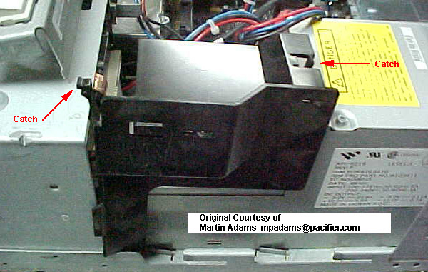
 

9577 Air Baffle for Fixed Disk Bay 4C FRU 92F0251

  The older 8557 and 9557 used a grey colored baffle, same FRU.

   This was used in older systems with hot running drives in 4C. Modern 1" high drives should run cool enough without it, but if you want to run a 7,200RPM (or higher) drive in your 77, you MIGHT want to help cool it as much as possible.

Pasteboard hack
   I built a baffle for a 9577 that went from the top air grill on the power supply over to the D: drive bay above the control module. Worked fine. A little duct tape, some pasteboard, and shazzam! I don't have a 77 anymore to give you dimensions.


PS/2 - 76/77 S Model Configures SCSI HD As 6,1
Symptom: 
   The 9576 or 9577 system configures the harddisk with a SCSI ID of 6,1 instead of 6,0. A POST error of 1047000 107 may also occur. 

Problem Isolation Aids:
1. This tip applies only if the 9576 or 9577 is a Model xUx, xNx,or xTx. 
2. This tip applies only if the unit is a 9576s, or 9577s. 

Fix:
1. The problem is caused by a failing SCSI adapter. The SCSI adapter, FRU P/N71G3576, should be replaced. 
2. If the symptom remains, utilise normal problem determination procedures to isolate the failing FRU or application. 


9595 Main Page