7568 DASD Module
@8EFD.ADF - SCSI
Cached Disk/Diskette Controller
DASD Module
Open DASD Module
Opened DASD Layout
HD Rails
HD Drive Shapes Supported
Floppy Drive Stuff
40 to 34 pin Cable Hack
ADF Section
DASD MODULE (#6222):
CR1 Run/Check
LED
CR2 Drive
in Use LED
F1 125v1.5A Littlefuse
F2,3 125v 2A Littlefuse
P1,2 Backplane connectors
P3,4,6 Drive power connections
P5 40 pin FD header (8570 style)
P7 Unk 4 pin header
P8 SCSI connector
U10 80C188
U17,21 30 pin SIMM sockets |
U22 SCSI BIOS Even
U29 Hitachi HM62256LFP-12T
U31 20.0 MHz osc
U37 OKI 15F7917
U43 57F2716 SCSI adapter ucode
U52 15F6903
U53 33F6715
U57 24.0 MHz osc
U62 82077-1 Floppy controller
U63 Adaptec AIC-6250EL |
The Disk Module allows for adding DASD to a Gearbox.
The Disk Module consists of a double-wide shroud and a Disk/Diskette Adapter
Card, to be plugged into the frame in place of two empty card shrouds.
The Disk/Diskette Adapter Card contains 0.5MB of DASD Cache Memory, and
supports up to two 1.6" high 3.5" drives and a 1.44MB Diskette Drive installed
inside the shroud. The DASD Module has a C60 SCSI port on the
bottom.
SCSI BIOS Upgrade Ready
The upgrade SCSI BIOS chips for the SCSI and SCSI w/cache
(92F2244/92F2245) work in this board, and probably all others. If you look
at the SCSI w/cache, single oscillator, the parts are the same.
NOTE: PS/2 adapters should
not be installed in the slot #9 position. This is due to limitations with
setup and diagnostic code recognizing such adapters in that position.
2.88MB Support
The D40 (possibly C40 as well) support the 2.88MB floppy.
It's in the setup options...
Set ID
Your C: MUST be set to ID6, a second HD MUST be set to ID5,
as the setup lacks selectable start sequence. The SCSI adapter itself is
ID7.
Something I haven't seen- if you add an auxiliary DASD
module to slots 1 and 2, the drives must use ID0 to ID4. The drives within
the Auxiliary DASD module are considered as external SCSI devices.
Open the DASD
Module
Folks, this is to help you keep your DASD module relatively
unscarred.
Pull up on one of the ears and twist the latches out. (Important to
remove them!). Now go to the back of the module and undo the two
catches. Can't miss them. The DASD module is the only one to have them.
Pull the cover out. It will pivot on the two tabs at the front edge.
NOTE If you left the latches on,
this will NOT work.
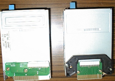
DASD Layout
Once you open the DASD up, the top swings back, held at the
bottom by the data and power cables.
HD Rails
Hard Drive Shapes
Supported
The 7568 requires the squarish 0661/0662/0663/0664 drives
to fit the 7568 specific drive rails. The mounting holes on the 1" high
0662 do NOT match. You can drill a new pair of screw holes in the rails,
but keep this in mind- the on-board SCSI is 50 pin, so why not keep with
the 0662/3/4 1GB-2GB range?
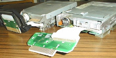
Floppy
Drive Stuff
The drive in the 7568 is used in the Model 70, PN 15F7503. It
is a modified ALPS DFP723D12F with a PCB screwed in place on the top. The
drive that came with an 8570 has a clear plastic sled screwed on, but the
same PN 15F7503. Another 8570 drive is a Mitsubishi MF355C-599MB.
Some pictures stolen from Alfred Arnold's page:
Remove the Floppy Drive
Remove the clear plastic spacers between the drive latches.
Unscrew the two screws on the outside of the shroud (they screw into the
FD's bottom!). Spread the two sets of latches one side at a time, pulling
up on the FD. Once the FD rails are past the latch, pull it back and up.
The floppy rails are held on with two screws per side.
The funky thick black bezel will come off quite easily AFTER you unscrew
the front rail screw. Trust me. Do NOT try to pry the thick bezel off,
it is rather ready to fall off once the front screws are half way out.
40-pin to 34-pin
Cable Hack
All hail Bob Eager!
His Making
a diskette drive adaptor provided me with the extremely important
pinout information that inspired the following Super High Intensity Tinkering
(S.H.I.T.).
The D40 BIOS (maybe C40 as well) supports the 2.88MB floppy
(with it's dust shutter!). But the 2.88MB has a different location for
it's 34 pin header and it's slightly offset, so the floppy cable HAS to
be longer.
Waiting for a 40 pin to 34 pin cable, 27 Feb
01
Martin Adams is sending me a 40-34 pin cable as we speak. His
picture of it looks a bit different from what I've tried.
Back to the normal channel...
My first attempt failed, I must see if it's the cable
or the drive. I got a 1.44MB to try now...
Bob had a normal hack, but with the help of Jolt cola
and a loose grip on reality, I came up with a higher hack (think outside
the box!). The MAD Hack eliminates the two loose conductors between the
headers, and has them securely fastened by the 40 pin connector itself.
No tape needed to keep the cable together...
Take needlenose pliers, pull the insulation displacing
points on the 40-pin header at 3, 6, 35, 36, 37, and 39. Leave 38 and 40
at the end.
Now use a 10" length of 34 conductor cable. Crimp
on the 34 pin header, Watch the orientation of the floppy header- on my
FD, the key points down. Thankfully, pin 1 on the floppy and pin 1 on the
DASD board are both to the left as you look at the opened module (with
the floppy shutter pointing towards you).
Now measure out 8". You should have about 2" past the
40 pin header. Now bring out 3 and 6, cut the rest of the conductors flush
at the 40 pin. Now bring them around the back, over 38 and 40 and
exit the connector towards the 34 pin header. Crimp. A little ticklish
getting 3 and 6 onto the slots of 38 and 40, but it's sooo much neater.
AdapterID
8EFD SCSI Cached Disk/Diskette Controller
SCSI Adapter Memory Location
Selects a 32kb memory block which this adapter will use
for it's BIOS ROM. There are five memory ranges.
<"Segment C000" >(mem c0000-c7fff),
"Segment C400" (mem c4000-cbfff), "Segment C800" (mem c8000-cffff), "Segment
CC00", mem cc000-d3fff), "Segment D000" (mem d0000-d7fff), "Segment D400"
(mem d4000-dbfff), "Segment D800" (mem d8000-dffff), "ROM Disabled"
SCSI I/O Address
Choose the I/O address for each adapter
<"3540-3547"
(io 3540h-3547)>, "3548-354F" (io 3548-354F), "3550-3557"
(io 3550h-3557), "3558-355F" (io 3558-355F), "3560-3567" (io
3560-3567), "3568-356F" (io 3568-356F), "3570-3577" (io 3570-3577),
"3578-357F" (io 3578-357F)
SCSI Arbitration Level
Select the arbitration level that SCSI will use to transfer
data.
<"Level C" (arb 12)>,
"Level D" (arb 13), "Level E" (arb 14), "Level 1" (arb 1), "Level
3" (arb 3), "Level 5" (arb 5", "Level 6" (arb 6), "Level 8"
(arb 8), "Level 9" (arb 9), "Level A" (arb 10), "Level B" (arb 11)
SCSI Adapter Fairness On/Off
This controls whether the adapter will release control
of the bus when it has been using it exclusively.
<"On" >, "Off"
ROM Wait State Disable
Enable/Disable ROM Wait State
<"Enable Wait State">,
"No Wait State"
SCSI Adapter Address (ID)
Change the SCSI ID of the adapter.
<"7">, "6",
"5", "4", "3", "2", "1", "0"
Address Burst Boundary
Determines the maximum number of bytes per burst
< "No Boundary">,
"32-Byte Boundary", "64-Byte Boundary", "128-Byte Boundary"
Diskette DMA Arbitration Level
DMA channel the diskette adapter will use to transfer
data.
<"Shared level 2
only" (ARB SharedArb 2)>
Diskette Adapter Fairness On/Off
Controls whether the diskette adapter will release control
of the bus when it has been using it exclusively.
<"Off">, "On"
Diskette Primary/Alternate Addresses
Primary or secondary address range of the diskette portion.
<"Primary 03F0-03F7"
(io 3F0-3f7 int 6)>, "Alternate 0370-0377" (io 370-377 int
6)
9595 Main
Page
|