7552 Power
7552 Power Supply Supply
AC Power Cord Hook-Up
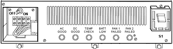
Front of Power Supply
Remove PSU
Dead PSU, or Is It Dead?
Status Light Meanings
Power Supply Voltages and Current
Nicad Battery
EVM Module
PSU Fan
Cleaning the PSU
Gearbox
Power
The 7552 is a direct-wire system, using a customer-provided
power cable to an applicable power source. 260 total watt worldwide, autoranging
(will detect and switch for 120 or 220) power supply, with two fans to
assure system cooling.
AC Power Cord
Hook-Up
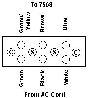
7552s wired for AC power have a terminal block mounted on the
left side (or upper left rear corner). The black wire (shield) on the system
side of the terminal DOES NOT attach
to the terminal block.
C - Terminal Cover screws
S - Terminal Block screws
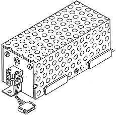
Power Supply
(with EVM installed)
PSU made by Power Systems, Inc, model PS1617 IBM P/N 60X8906
PSU Connector Pinout
Remove PSU
Turn power switch off on PSU. Unscrew the three screws
on the bottom front edge. Grab on the cutout around the EVM/Battery pack
on the left and grab the right corner of the PSU (though you might try
the rightmost captive screw). Rock the PSU a little as you pull it out.
The plug is at the back of the PSU behind the power switch. It resembles
a mutant 95 planar plug. Do NOT grab
the black plastic guard around the power switch!!!
NOTE: The three screws are NOT
captive ones like on the 7568! They must be totally removed to pull the
PSU out.
Dead PSU or Is
It Really Dead?
I had two 7568s, one powered up, the other didn't. Swapped
the PSUs, one worked in both cases, the other didn't work at all. These
babies are built even heavier than a 95A PSU, so I was puzzled.
Dr. Jim did the office call
and says:
The tabs holding the thumbscrews at the bottom front of
the PS were tweaked backwards. Straightened them out so the PS seated
fully.
Status Lights
Meaning
|
AC
|
DC
|
TEMP
|
BATT
|
FAN 1
|
FAN2
|
Possible Problem
|
|
O
|
X
|
O
|
O
|
O
|
O
|
1. AC power missing
2. Defective power supply |
|
X
|
O
|
O
|
O
|
O
|
O
|
Defective Power Supply |
|
X
|
X
|
X
|
O
|
O
|
O
|
1. Hi temp (poor ventilation?)
2. Defective power supply |
|
X
|
X
|
O
|
X
|
O
|
O
|
1. Battery discharged or disconnected
2. Defective power supply |
|
X
|
X
|
O
|
O
|
X
|
O
|
1. Fan 1 Malfunction
2. Defective power supply |
|
X
|
X
|
O
|
O
|
O
|
X
|
1. Fan 2 malfunction
2. Defective power supply |
|
X
|
X
|
O
|
O
|
O
|
O
|
AC OK - Power supply OK |
Power Source Choices
When the system is turned on, the PSU senses the applied
power source. If AC power is present, the system starts and runs with AC
as primary power. If DC power is present, it is used as a backup power
source (requires EVM for extended backup time).
If no AC power is present, the system starts and runs
off DC power, if DC power is available at the battery connector (requires
EVM to be installed). There is no backup capability in this configuration.
Don't try running system off battery pack!!!
The system sets operating mode (AC or DC) when the system
is turned on. It remains in that mode until the power switch is turned
off.
AC Specs
120 / 220 vac
4.0A / 2.0A
Single phase.
Power usage .45KVA
47-63Hz
AC Power Cable
Any cable used must be a minimum of 18AWG with ground.
Power Supply Values
Max output 260 W
+5V @ 22A -5V @ 0.3A
+12V @ 4A -12V @ 1A
+6V @ 5mA
Battery Charger +28V @80mA
Fan Supply 15W max
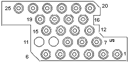
PSU Pinout
|
Pin
|
Function
|
Pin
|
Function
|
|
1
|
+6v @ 5mA
|
13,15-20,22,24
|
GND
|
|
2-4,7,8
|
+5v @ 22A
|
14
|
-PR PWR CK
|
|
5
|
-12v @ 1A
|
21
|
-P/S CK
|
|
6
|
+12v @ 4A
|
23
|
BKUP DISC
|
|
9
|
-5v @ 300mA
|
25
|
DC PWR GOOD
|
|
12
|
-TEMP CK
|
|
|
BATTERY, NICAD
(INTERNAL) (#6221) (P/N 15F8625):
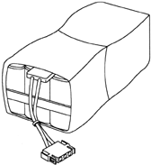
This internally mounted battery allows continuous operation through
brief main power interruptions (nominal 1.5 seconds default). Also, if
the interruption continues beyond this period, the battery maintains DC
voltages to allow the system to perform an orderly shutdown.
NOTE: Shutdown is limited to max
of 10 sec under hardware control. Software control shutdown depends on
the electrical load and the battery capacity, and may be limited to 10
seconds. Longer shutdown periods require external battery backup, which
requires an EVM.
The battery pack is 21 (twenty-one) Sony Cadnica KR-SCH 1.2v 1200mAh,
Standard charge14-16 hrs at 120mA, recommended trickle charge 40mA.
Marked "Plainview Batteries, Inc" mfd- 9104 IBM replacement PN
15F8625
EXTERNAL VOLTAGE MODULES
(#6231 AND #6528):
 These
EVM features allow the connection of an external DC voltage source either
for additional battery backup to the main AC power, or as a main DC power
source. No other external voltages are to be used as a main source or as
a backup. These
EVM features allow the connection of an external DC voltage source either
for additional battery backup to the main AC power, or as a main DC power
source. No other external voltages are to be used as a main source or as
a backup.
EVM #6231 24 volts DC.
EVM #6528 48 or 60 volts DC.
NOTE: Either one of these EVMs (with
a connected external DC voltage source), or the internal nicad battery
(#6221) must be ordered and installed to retain system set up information
during periods when the system is shut down.
The EVM provides RFI filtering, reverse polarity protection, and over
voltage protection.
WARNING: A fully populated Gearbox
requires up to 30A on the DC line. Use a minimum of 14AWG
PSU Fan
ETRI Model 98DW 98DW1LP31 203, 12v (8-15v) at 5.2W (under
.5A)
Filter Use
The 7568 can use optional filters in the PSU compartment.
Use of filters degrades the maximum temperature decreases by 9°F/5°C.
Changing Airflow Direction
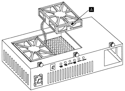
Remove the PSU. Flip it upside down. If you can see the
ETRI sticker on the fan hub, the PSU is set to blow down through the shrouds.
This direction is used for the filter configuration. Unfortunately, the
heat generated by the PSU is now blown through the shrouds.
If you see a silver hub, the PSU is set to suck air up
through the shrouds and out through the grilles in the PSU compartment.
This is good because the heat from the PSU is not blown through the populated
shrouds.
Remove the three standard screws in each fan housing. Pull
them out and flip them over to whatever way you want. If you are unsure
about the direction, there are two arrows embossed on the fan housing,
showing fan rotation AND airflow direction.
Cleaning the PSU
Hooray! I stumbled onto this working on the fans...
At first look, it's grim. Rivets everywhere. Don't give up. Flip
PSU upside-down. Unplug fan power connectors. Remove all fan screws. Pull
up on grille and push the fan power connectors through using a flat bladed
screwdriver. Now the grill comes off, and the majority of the PSU components
are exposed.
Copper heatsinks! Stud power diodes!
9595 Main
Page
|